Page 233 of 390

ENG
4 - 23
ZYLINDER UND KOLBEN
Arbeitsumfang:1 Zylinder demontieren
2 Kolben demontieren
Arbeitsumfang
Reihen- folgeBauteil Anz. Bemerkungen
ZYLINDER UND KOLBEN
DEMONTIEREN
Vorbereitungsarbeiten Zylinderkopf Siehe dazu den Abschnitt “ZYLINDER-
KOPF ”.
1 Steuerkettenschiene (Auslass) 1
2 Zylinder 1
3 Passh ülse 2
4 Dichtung 1
5 Kolbenbolzen-Sicherungsring 2 Spezialwerkzeug verwenden.
Siehe dazu den Abschnitt “DEMON-
TAGE-EINZELHEITEN ”.
6 Kolbenbolzen 1
7 Kolben 1
8 1. Kompressionsring 1
Siehe dazu den Abschnitt “DEMON-
TAGE-EINZELHEITEN ”.
92. Kolbenring 1
10 Ölabstreifring 1
2
1
CYLINDRE ET PISTON
ZYLINDER UND KOLBEN
CYLINDRE ET PISTON
Organisation de la d épose: 1 Dépose du cylindre 2 Dépose du piston
Organisation de la d épose Ordre Nom de la pi èce Q ’té Remarques
DEPOSE DES CYLINDRES ET
DES PISTONS
Pr éparation à la d épose Culasse Se reporter à la section “CULASSE ”.
1 Patin de cha îne de distribution
( é chappement) 1
2 Cylindre 1
3 Goujon 2
4 Joint 1
5 Clip d ’axe de piston 2
Utiliser l’outil sp écial.
Se reporter à la section “POINTS DE
DEPOSE ”.
6 Axe de piston 1
7 Piston 1
8 Segment de piston (segment de feu) 1
Se reporter à la section “POINTS DE
DEPOSE ”.
9 Segment de piston (segment d
’étan-
ch éit é) 1
10 Segment racleur d ’huile 1
2
1
Page 234 of 390
4 - 24
ENGCYLINDER AND PISTON
REMOVAL POINTS
Piston
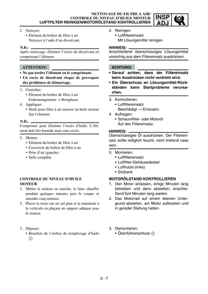
1. Remove:Piston pin clips 1
Piston pin 2
Piston 3
NOTE:
Before removing the piston pin clip, cover the
crankcase opening with a clean towel or rag
to prevent the clip from falling into the crank-
case cavity.
Before removing each piston pin, deburr the
clip groove and pin hole area. If the piston
pin groove is deburred and the piston pin is
still difficult to remove, use the piston pin
puller set 4.
Piston pin puller set:
YU-01304/90890-01304
Piston ring
1. Remove:
Piston rings
NOTE:
Spread the end gaps apart while at the same
time lifting the piston ring over the top of the
piston crown, as shown in the illustration.
INSPECTION
Cylinder and piston
1. Inspect:
Cylinder and piston walls
Vertical scratches → Replace cylinder
and piston.
Page 235 of 390

4 - 24
ENG
DEMONTAGE-EINZELHEITEN
Kolben
1. Demontieren:Kolbenbolzen-Sicherungsringe 1
Kolbenbolzen 2
Kolben 3
HINWEIS:
Vor dem Ausbau des Kolbenbolzen-Siche-
rungsringes das Kurbelgeh äuse mit einem
sauberen Tuch abdecken, damit der Siche-
rungsring nicht hineinfallen kann.
Vor dem Ausbau des Kolbenbolzens den
Bereich der Sicherungsring-Nut und des Kol-
benbolzenauges entgraten. L ässt sich der
Kolbenbolzen auch danach nur schwer
l ö sen, den Kolbenbolzen-Abzieher 4 ver-
wenden.
Kolbenringe
1. Demontieren: Kolbenringe
HINWEIS:
Wie in der Abbildung gezeigt die Ringenden
spreizen und dabei den Kolbenring hochschie-
ben.
Kolbenbolzen-Abzieher:
YU-01304/90890-01304
KONTROLLE
Zylinder und Kolben
1. Kontrollieren:
Zylinder und Kolbenhemd
In Laufrichtung riefig → Zylinder und Kol-
ben erneuern.
CYLINDRE ET PISTON
ZYLINDER UND KOLBEN
POINTS DE DEPOSE
Piston
1. D époser:
Clips d ’axes de pistons 1
Axe de piston 2
Piston 3
N.B.:
Avant de d époser le clip d ’axe de piston, couvrir
le carter d ’un chiffon propre pour éviter que le
clip ne tombe dans le carter.
Avant de retirer chaque axe de piston, ébavurer la
gorge du clip et le pourtour du trou de l ’axe. Si la
gorge de l ’axe de piston est ébavur ée et que l ’axe
du piston reste difficile à d égager, utiliser
l’ extracteur d ’axe de piston 4.
Segment de piston
1. D époser:
Segments de piston
N.B.:
Ecarter les becs tout en soulevant le segment de pis-
ton par dessus la calotte du piston, comme illustr é.
Kit extracteur d ’axe de piston:
YU-01304/90890-01304
CONTROLE
Cylindre et piston
1. Contr ôler:
Parois du cylindre et du piston
Rayures verticales → Remplacer le cylindre
et le piston.
Page 236 of 390

4 - 25
ENGCYLINDER AND PISTON
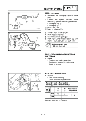
2. Measure:Piston-to-cylinder clearance
Measurement steps:
1st step:
Measure the cylinder bore “C ” with a cylin-
der bore gauge.
a 10 ~ 15 mm (0.39 ~ 0.59 in) from the top of
the cylinder
NOTE:
Measure cylinder bore
“C ” by taking side-to-
side and front-to-back measurements of the
cylinder. Then, find the average of the mea-
surements.
Standard Wear
limit
Cylinder
bore “C ” 35.995 ~ 36.015 mm
(1.4171 ~ 1.4179 in) 36.05 mm
(1.419 in)
C =
If out of specification, replace the cylinder,
and replace the piston and piston rings as
set.
2nd step:
Measure the piston skirt diameter “P ” with
a micrometer.
a 5 mm (0.20 in) from the piston bottom edge.
Piston size P
Standard 35.960 ~ 35.980 mm
(1.4157 ~ 1.4165 in)
If out of specification, replace the piston
and piston rings as a set.
3rd step:
Calculate the piston-to-cylinder clearance
with following formula:
Piston-to-cylinder clearance =
Cylinder bore “C ” –
Piston skirt diameter “P ”
Piston-to-cylinder clearance:
0.030 ~ 0.040 mm
(0.0012 ~ 0.0016 in)
: 0.15 mm (0.0059 in)
If out of specification, replace the cylinder,
and replace the piston and piston rings as
set.
2
X + Y
Page 237 of 390

4 - 25
ENG
2. Messen:Kolben-Laufspiel
Messung:
1. Schritt:
Die Zylinderbohrung “C ” mit einer Innen-
messschraube messen.
a 10
–15 mm (0,39 –0,59 in) von der Oberkante
des Zylinders
HINWEIS: Die Zylinderbohrung “C ” sowohl parallel als
auch im rechten Winkel zum Kolbenbolzen
messen. Anschlie ßend den Durchschnitt der
gemessenen Werte ermitteln.
StandardVerschlei ß-
grenze
Zylinder-
bohrung “C ” 35,995
–36,015 mm
(1,4171 –1,4179 in) 36,05 mm
(1,419 in)
C =
Falls nicht nach Vorgabe, Zylinder sowie
Kolben und Kolbenringe erneuern.
2. Schritt:
Den Kolbenschaft-Durchmesser “P ” mit
einer B ügelmessschraube messen.
a 5 mm (0,20 in) oberhalb der Unterkante des
Kolbens.
Kolbengr
öße P
Standard 35,960
–35,980 mm
(1,4157 –1,416 in)
Falls nicht nach Vorgabe, Kolben samt
Kolbenringen erneuern.
3. Schritt:
Das Kolben-Laufspiel nach folgender For-
mel ermitteln:
Kolben-Laufspiel =
Zylinderbohrung “C ” –
Kolbenschaft-Durchmesser “P ”
Kolben-Laufspiel:
0,030 –0,04 mm
(0,0012 –0,0016 in)
: 0,15 mm (0,0059 in)
Falls nicht nach Vorgabe, Zylinder sowie
Kolben und Kolbenringe erneuern.
2
X + Y
CYLINDRE ET PISTON
ZYLINDER UND KOLBEN
2. Mesurer:
Jeu entre piston et cylindre
Proc édure de mesure:
1 ère étape:
Mesurer l ’al ésage de cylindre “C ” à l ’aide
d ’un comparateur d ’al ésage de cylindre.
a 10
à 15 mm (0,39 à 0,59 in) depuis le haut du
cylindre
N.B.:
Mesurer l ’al ésage de cylindre “C ” en mesurant
le cylindre de c ôté à c ôté et d ’avant en arri ère.
Calculer ensuite la moyenne des valeurs obte-
nues.
Standard Limite
d ’usure
Al ésage
de cylin- dre “C ” 35,995
à 36,015 mm
(1,4171 à 1,4179 in) 36,05 mm
(1,419 in)
C =
Si le r ésultat est hors sp écifications, remplacer
le cylindre et remplacer ensemble le piston et
ses segments.
2 ème étape:
Mesurer le diam ètre “P ” de la jupe de piston à
l ’ aide d ’un microm ètre.
a 5 mm (0,20 in) depuis le bord inf
érieur du piston.
Taille du piston P
Standard 35,960
à 35,980 mm
(1,4157 à 1,4165 in)
Si hors sp écifications, remplacer ensemble le
piston et les segments de piston.
3 ème étape:
Calculer le jeu entre le piston et le cylindre au
moyen de la formule suivante:
Jeu entre piston et cylindre =
al ésage de cylindre “C ” –
diam ètre de jupe de piston “P ”
Jeu entre piston et cylindre:
0,030 à 0,040 mm
(0,0012 à 0,0016 in)
: 0,15 mm (0,0059 in)
Si le r ésultat est hors sp écifications, remplacer
le cylindre et remplacer ensemble le piston et
les segments de piston.
2
X + Y
Page 238 of 390

4 - 26
ENGCYLINDER AND PISTON
Piston ring
1. Measure:Ring side clearance
Use a thickness gauge.
Out of specification → Replace the piston
and rings as a set.
NOTE:
Clean carbon from the piston ring grooves and
rings before measuring the side clearance.
2. Position: Piston ring
(in cylinder)
NOTE:
Insert a ring into the cylinder and push it
approximately 10 ~ 15 mm (0.39 ~ 0.59 in) into
the cylinder. Push the ring with the piston
crown so that the ring will be at a right angle to
the cylinder bore.
a 10 ~ 15 mm (0.39 ~ 0.59 in)
3. Measure:
Ring end gap
Out of specification → Replace.
NOTE:
You cannot measure the end gap on the
expander spacer of the oil control ring. If the oil
control ring rails show excessive gap, replace
all three rings.
Thickness gauge:
YM-34483/90890-03079
Side clearance
Standard Limit
Top ring 0.020 ~ 0.070 mm
(0.0008 ~ 0.0028 in) 0.12 mm
(0.005 in)
2nd ring 0.020 ~ 0.060 mm
(0.0008 ~ 0.0024 in) 0.12 mm
(0.005 in)
End gap
Standard Limit
Top ring 0.10 ~ 0.25 mm
(0.004 ~ 0.010 in) 0.50 mm
(0.020 in)
2nd ring 0.15 ~ 0.30 mm
(0.006 ~ 0.012 in) 0.65 mm
(0.026 in)
Oil ring 0.20 ~ 0.70 mm
(0.008 ~ 0.028 in) —
Page 239 of 390

4 - 26
ENG
Kolbenringe
1. Messen:Ringnutspiel
Mit einer F ühlerlehre.
Nicht nach Vorgabe → Kolben samt Kol-
benringen erneuern.
HINWEIS: Vor der Messung des Ringnutspiels m üssen
die Ölkohleablagerungen von den Kolbenrin-
gen und Ringnuten entfernt werden.
2. Anordnen:
Kolbenringe
(im Zylinder)
HINWEIS:
Den Kolbenring ca. 10 –15 mm (0,39 –0,59 in)
in den Zylinder einschieben. Den Kolbenring
mit dem Kolbenboden in die Zylinderbohrung
schieben, sodass der Ring rechtwinklig im
Zylinder sitzt.
a 10
–15 mm (0,39 –0,59 in)
3. Messen:
Kolbenring-Sto ß
Nicht nach Vorgabe → Erneuern.
HINWEIS:
Der Sto ß der Ölabstreifring-Expanderfeder
kann nicht gemessen werden. Wenn der Sto ß
der Ölabstreifschneiden nicht im Sollbereich
liegt, m üssen alle Kolbenringe erneuert werden.
F ühlerlehre:
YM-34483/90890-03079
Ringnutspiel
Standard Grenzwert
1. Kompres-
sionsring 0,020
–0,070 mm
(0,0008 –0,0028 in) 0,12 mm
(0,005 in)
2. Kompres-
sionsring 0,020
–0,060 mm
(0,0008 –0,0024 in) 0,12 mm
(0,005 in)
Ringsto ß
Standard Grenzwert
1. Kompres-
sionsring 0,10
–0,25 mm
(0,004 –0,010 in) 0,50 mm
(0,020 in)
2. Kompres-
sionsring 0,15
–0,30 mm
(0,006 –0,012 in) 0,65 mm
(0,026 in)
Ö labstreif-
ring 0,20
–0,70 mm
(0,008 –0,028 in) —
CYLINDRE ET PISTON
ZYLINDER UND KOLBEN
Segment de piston
1. Mesurer:
Jeu lat éral du segment
Utiliser un calibre d ’épaisseur.
Hors sp écifications → Remplacer ensemble
le piston et les segments de piston.
N.B.:
Eliminer les d ép ôts de calamine des gorges des seg-
ments de piston et des segments avant de mesurer le
jeu lat éral.
2. Position: Segment de piston
(dans le cylindre)
N.B.:
Ins érer un segment dans le cylindre et l ’enfoncer
d ’environ 10 à 15 mm (0,39 à 0,59 in). Pousser le seg-
ment à l ’aide de la calotte de piston de mani ère que le
segment fasse un angle droit avec l ’al ésage du cylindre.
a 10
à 15 mm (0,39 à 0,59 in)
3. Mesurer:
Ecartement des becs
Hors sp écifications → Remplacer.
N.B.:
Il n ’est pas possible de mesurer l ’écartement des becs
de la bague extensible du segment racleur d ’huile. Si
les rails du segment racleur d ’huile pr ésentent un
écartement excessif, remplacer les trois segments.
Calibre d ’épaisseur:
YM-34483/90890-03079
Jeu lat éral
Standard Limite
Segment
de feu 0,020
à 0,070 mm
(0,0008 à 0,0028 in) 0,12 mm
(0,005 in)
Segment
d ’é tanch éit é0,020 à 0,060 mm
(0,0008 à 0,0024 in) 0,12 mm
(0,005 in)
Ecartement des becs
Standard Limite
Segment
de feu 0,10
à 0,25 mm
(0,004 à 0,010 in) 0,50 mm
(0,020 in)
Segment
d ’é tanch éit é0,15 à 0,30 mm
(0,006 à 0,012 in) 0,65 mm
(0,026 in)
Segment
racleur
d ’huile 0,20
à 0,70 mm
(0,008 à 0,028 in) —
Page 240 of 390
4 - 27
ENGCYLINDER AND PISTON
Piston pin
1. Inspect:Piston pin
Blue discoloration/grooves →
Replace, then inspect the lubrication sys-
tem.
2. Measure: Piston pin outside diameter
Piston pin bore inside diameter
ASSEMBLY AND INSTALLATION
Piston
1. Install: Piston rings
(onto the piston)
NOTE:
Be sure to install the piston rings so that the
manufacturer ’s marks or numbers are
located on the upper side of the rings.
Lubricate the piston and piston rings liberally
with engine oil.
Measurement steps:
Measure the piston pin outside diameter
a .
If out of specification, replace the piston
pin.
Outside diameter (piston pin): 11.996 ~ 12.000 mm
(0.4723 ~ 0.4724 in)
:11.976 mm (0.4715 in)
Measure the piston inside diameter b.
If out of specification, replace the piston.
Inside diameter (piston): 12.002 ~ 12.013 mm
(0.4725 ~ 0.4730 in)
: 12.043 mm (0.4741 in)