Page 209 of 390
ENG
4 - 11
ArbeitsumfangReihen-folgeBauteil Anz. Bemerkungen
8 Steuerkettenspanner 1 Siehe dazu den Abschnitt “DEMON-
TAGE-EINZELHEITEN ”.
9 Dichtung 1
10 Nockenwellenrad 1
11 Zylindereinlass-Anschluss 1
12 Zylinderkopf 1 Siehe dazu den Abschnitt “DEMON-
TAGE-EINZELHEITEN ”.
13 Passh ülse 2
14 Dichtung 1
1
CULASSE
ZYLINDERKOPF
Organisation de la d épose Ordre Nom de la pi èce Q ’té Remarques
8 Tendeur de cha îne de distribution 1
Se reporter à la section “POINTS DE
DEPOSE ”.
9 Joint 1
10 Pignon d ’arbre à cames 1
11 Tubulure d ’admission 1
12 Culasse 1 Se reporter à la section “POINTS DE
DEPOSE ”.
13 Goujon 2
14 Joint 1
1
Page 210 of 390
4 - 12
ENGCYLINDER HEAD
REMOVAL POINTS
Cylinder head
1. Align:“I” mark
(with stationary pointer)
Checking steps:
Turn the crankshaft counterclockwise with
a wrench.
Align the “I” mark a on the rotor with the
stationary pointer b on the crankcase
cover. When the “I” mark is aligned with
the stationary pointer, the piston is at the
Top Dead Center (T.D.C.).
NOTE:
In order to be sure that the piston is at Top
Dead Center, the “I” mark c on the cam-
shaft sprocket must align with the station-
ary pointer d on the cylinder head as
shown in the illustration.
If there is no valve clearance, rotate the
crankshaft counterclockwise one turn.
b
a
c
d
2. Loosen:
Camshaft sprocket bolt 1
3. Remove:
Timing chain tensioner
Camshaft sprocket 2
NOTE:
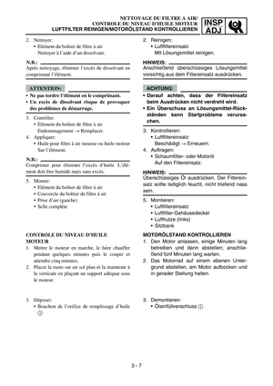
Fasten a safety wire to the timing chain 3 to
prevent it from falling into the crankcase.
Remove the bolt 1 while holding the rotor
nut with a wrench.
12
3
Page 211 of 390

4 - 12
ENG
DEMONTAGE-EINZELHEITEN
Zylinderkopf
1. Ausrichten:“I” Markierung
(auf die Gegenmarkierung)
Kontrolle:
Die Kurbelwelle mit einem Schrauben-
schl üssel gegen den Uhrzeigersinn dre-
hen.
Die “I” Markierung a am Rotor auf die ent-
sprechende Gegenmarkierung b am Kur-
belgeh äuse ausrichten. Wenn die “I”
Markierung mit der entsprechenden
Gegenmarkierung fluchtet, befindet sich
der Kolben im oberen Totpunkt (OT).
HINWEIS: Der Kolben befindet sich im oberen Tot-
punkt, wenn die “I” Markierung c am
Nockenwellenrad und die Gegenmarkie-
rung d am Zylinderkopf wie in der Abbil-
dung gezeigt fluchten.
Die Kurbelwelle gegebenenfalls um eine
Umdrehung gegen den Uhrzeigersinn dre-
hen.
2. Lockern:
Nockenwellenrad-Schraube 1
3. Demontieren: Steuerkettenspanner
Nockenwellenrad 2
HINWEIS:
Die Steuerkette mit einem Draht 3 sichern,
damit sie nicht in das Kurbelgeh äuse hinab-
f ä llt.
Beim Demontieren der Schraube 1 die
Rotor-Mutter mit einem Schraubenschl üssel
gegenhalten.
CULASSE
ZYLINDERKOPF
POINTS DE DEPOSE
Culasse
1. Aligner:
Rep ère “I”
(avec index fixe)
Proc édure de contr ôle:
A l ’aide d ’une cl é, tourner le vilebrequin dans
le sens inverse des aiguilles d ’une montre.
Aligner le rep ère “I” a du rotor avec l ’index
fixe b du couvercle de carter. Lorsque le
rep ère “I” est align é avec l ’index fixe, le piston
est au Point Mort Haut (P.M.H.).
N.B.:
Le piston est au Point Mort Haut lorsque le
rep ère “I” c du pignon d ’arbre à cames et
l ’ index fixe d de la culasse sont align és,
comme illustr é.
S’il n ’y a pas de jeu aux soupapes, tourner le
vilebrequin d ’un tour dans le sens inverse des
aiguilles d ’une montre.
2. Desserrer:
Boulon du pignon d ’arbre à cames 1
3. D époser:
Tendeur de cha îne de distribution
Pignon d ’arbre à cames 2
N.B.:
Attacher la cha îne de distribution à l ’aide d ’un fil
m étallique 3 pour l ’emp êcher de tomber dans le
carter moteur.
Déposer le boulon 1 tout en maintenant l ’écrou
de rotor à l ’aide d ‘une cl é.
Page 212 of 390

4 - 13
ENGCYLINDER HEAD
4. Remove:Cylinder head
NOTE:
Loosen the bolts and nuts in their proper
loosening sequence.
Start by loosening each bolt and nut 1/2 turn
until all are loose.1
2
5
64
3
ASSEMBLY AND INSTALLATION
1. Install:
Cylinder head
2. Tighten: Nuts
Bolts
NOTE:
Apply the engine oil on the contact surfaces
of the nuts and copper washers.
Apply the engine oil on the thread and con-
tact surface of the bolts.
Follow the numerical order shown in the illus-
tration. Tighten the bolts and nuts in two
stages.
6
5
2
13
4
T R..22 Nm (2.2 m · kg, 16 ft · lb)
T R..10 Nm (1.0 m · kg, 7.2 ft · lb)
3. Install:
Camshaft sprocket 1
Installation steps:
Turn the crankshaft counterclockwise until
the “I” mark a on the rotor is aligned with
the stationary pointer b on the crankcase
cover.
Align the “I” mark c on the camshaft
sprocket with the stationary pointer d on
the cylinder head.
Fit the timing chain 2 onto camshaft
sprocket and install the camshaft sprocket
on the camshaft.
NOTE:
When installing the camshaft sprocket, keep
the timing chain as tense as possible on the
exhaust side.
b
a
1
2
c
d
Page 213 of 390

4 - 13
ENG
4. Demontieren:Zylinderkopf
HINWEIS:
Die Muttern und Schrauben m üssen in der
richtigen Reihenfolge gelockert werden.
Sämtliche Schrauben und Muttern zun ächst
um eine halbe Umdrehung lockern.
ZUSAMMENBAU UND MONTAGE
1. Montieren: Zylinderkopf
2. Festziehen: Muttern
Schrauben
HINWEIS:
Motor öl auf die Kontaktfl ächen der Muttern
und Kupferscheiben auftragen.
Die Gewinde und Kontaktfl ächen der
Schrauben mit Motor öl bestreichen.
Die abgebildete Reihenfolge beachten. Die
Schrauben und Muttern in zwei Schritten
festziehen.
T R..22 Nm (2,2 m · kg, 16 ft · lb)
T R..10 Nm (1,0 m · kg, 7,2 ft · lb)
3. Montieren:
Nockenwellenrad 1
Montage:
Die “I” Markierung a am Rotor auf die ent-
sprechende Gegenmarkierung b am Kur-
belgeh äuse ausrichten.
Die “I” Markierung c am Nockenwellenrad
auf die entsprechende Gegenmarkierung
d am Zylinderkopf ausrichten.
Die Steuerkette 2 am Nockenwellenrad
anbringen und dann das Nockenwellenrad
an der Nockenwelle montieren.
HINWEIS: Bei der Montage des Nockenwellenrads
darauf achten, dass die Steuerkette an der
Auslassseite m öglichst straff ist.
CULASSE
ZYLINDERKOPF
4. D époser:
Culasse
N.B.:
Desserrer les boulons et écrous dans l ’ordre de
desserrage indiqu é.
Desserrer d ’abord chaque boulon et écrou de 1/2
tour.
ASSEMBLAGE ET MONTAGE
1. Monter: Culasse
2. Serrer: Ecrous
Boulons
N.B.:
Appliquer de l ’huile moteur sur les surfaces de
contact des écrous et rondelles en cuivre.
Appliquer de l ’huile moteur sur les filets et la sur-
face de contact des boulons.
Suivre l ’ordre num érique indiqu é dans l ’illustra-
tion. Serrer les boulons et les écrous en deux éta-
pes.
T R..22 Nm (2,2 m · kg, 16 ft · lb)
T R..10 Nm (1,0 m · kg, 7,2 ft · lb)
3. Monter:
Pignon d ’arbre à cames 1
Proc édure de montage:
Tourner le vilebrequin dans le sens inverse des
aiguilles d ’une montre jusqu ’à ce que le rep ère
“ I” a du rotor soit align é avec l ’index fixe b
du couvercle de carter.
Aligner le rep ère “I” c du pignon d ’arbre à
cames avec l ’index fixe d de la culasse.
Monter la cha îne de distribution 2 sur le
pignon d ’arbre à cames puis monter ce dernier
sur l ’arbre à cames.
N.B.:
En reposant le pignon d ’arbre à cames, maintenir
la cha îne de distribution aussi tendue que possi-
ble du c ôté é chappement.
Page 214 of 390

4 - 14
ENGCYLINDER HEAD
CAUTION:
.Do not turn the crankshaft during instal-
lation of the camshaft. Damage or
improper valve timing will result.
Remove the safety wire from the timing
chain.
4. Install:
Timing chain tensioner
Installation steps:
Remove the tensioner cap bolt 1 and
spring 2.
Release the timing chain tensioner one-
way cam 3 and push the tensioner rod 4
all the way in.
Install the tensioner with a new gasket 5
onto the cylinder.
T R..
Timing chain tensioner bolt: 10 Nm (1.0 m kg, 7.2 ft lb)
Install the spring 2 and cap bolt 1.
Tighten the bolt (with O-ring) to the speci-
fied torque.
T R..
Cap bolt:
8 Nm (0.8 m kg, 5.8 ft lb)
5. Install:
Washer
Camshaft sprocket bolt 1
NOTE:
Install the bolt 1 while holding the rotor nut
with a wrench.
6. Check:
Rotor “I” mark
Align with the crankcase cover stationary
pointer.
Valve clearance
Out of specification → Adjust.
Refer to the “VALVE CLEARANCE
ADJUSTMENT ” section in CHAPTER 3.
1
T R..26 Nm (2.6 m · kg, 19 ft · lb)
Page 215 of 390

4 - 14
ENG
ACHTUNG:
.Die Kurbelwelle darf während der
Nockenwellen-Montage nicht gedreht
werden. Dies f ührt zu Sch äden oder fal-
schen Ventilsteuerzeiten.
Den Draht von der Steuerkette abnehmen.
4. Montieren:
Steuerkettenspanner
Montage:
Die Steuerkettenspanner-Verschluss-
schraube 1 und Feder 2 demontieren.
Den Steuerkettenspanner- Sperrmecha-
nismus 3 freigeben und den St ößel 4
ganz hineindr ücken.
Den Steuerkettenspanner mit einer neuen
Dichtung 5 am Zylinder montieren.
T R..
Steuerkettenspanner-Schraube:
10 Nm (1,0 m kg, 7,2 ft lb)
Die Feder 2 und Verschlussschraube 1
montieren.
Die Schraube (samt O-Ring) vorschrifts-
m äß ig festziehen.
T R..
Verschlussschraube:
8 Nm (0,8 m kg, 5,8 ft lb)
5. Montieren:
Beilagscheibe
Nockenwellenrad-Schraube 1
HINWEIS:
Beim Montieren der Schraube 1 die Rotor-
Mutter mit einem Schraubenschl üssel gegen-
halten.
6. Kontrollieren:
“I” Markierung am Rotor
Auf die Gegenmarkierung am Kurbelge-
h äuse ausrichten.
Ventilspiel
Nicht nach Vorgabe → Korrigieren.
Siehe dazu den Abschnitt “VENTILSPIEL
EINSTELLEN ” im KAPITEL 3.
T R..26 Nm (2,6 m · kg, 19 ft · lb)
CULASSE
ZYLINDERKOPF
ATTENTION:
.Veiller à ce que le vilebrequin reste immobile
pendant la repose de l ’arbre à cames. Tout
mouvement risquerait de provoquer des dom-
mages ou un mauvais r églage du calage de
distribution.
Détacher le fil m étallique de la cha îne de dis-
tribution.
4. Monter: Tendeur de cha îne de distribution
Proc édure de montage:
Déposer le boulon capuchon
1 du tendeur de
cha îne et le ressort
2.
Rel âcher la came à sens unique
3 du tendeur
de cha îne de distribution et enfoncer compl ète-
ment la tige du tendeur 4.
Monter le tendeur et un joint neuf
5 sur le
cylindre.
T R..
Boulon de tendeur de cha îne de distribution:
10 Nm (1,0 m kg, 7,2 ft lb)
Reposer le ressort
2 et le boulon capuchon
1.
Serrer le boulon (avec le joint torique) au cou-
ple sp écifi é.
T R..
Boulon capuchon:
8 Nm (0,8 m kg, 5,8 ft lb)
5. Monter:
Rondelle
Boulon du pignon d ’arbre à cames
1
N.B.:
Reposer le boulon 1 tout en maintenant l
’écrou de
rotor à l ’aide d ‘une cl é.
6. Contr ôler:
Rep ère “I” du rotor
Aligner avec l ’index fixe du couvercle de car-
ter.
Jeu aux soupapes
Hors sp écifications
→ R
égler.
Se reporter à la section “REGLAGE DU JEU
AUX SOUPAPES ” au CHAPITRE 3.
T R..26 Nm (2,6 m · kg, 19 ft · lb)
Page 216 of 390
4 - 15
ENGCAMSHAFT AND ROCKER ARMS
CAMSHAFT AND ROCKER ARMS
Extent of removal: 1 Rocker arm removal
2 Camshaft removal
Extent of removal Order Part name Q ’ty Remarks
CAMSHAFT AND ROCKER
ARMS REMOVAL
Preparation for removal Cylinder head Refer to “CYLINDER HEAD ” section.
1 Rocker arm shaft 2 Use special tool. Refer to “REMOVAL POINTS ”.
2Rocker arm 2
3 Camshaft bearing retainer 1
4Camshaft 1
5 Valve clearance adjust screw locknut 2
6 Valve clearance adjust screw 2
2
1