Page 425 of 513

ENGINE
ELECTRICAL
SYSTEM
2
Remove
two
bolts
llsed
to
secure
the
starting
motor
on
the
clutch
housing
Pull
the
starter
assembly
forward
and
remove
the
starting
motor
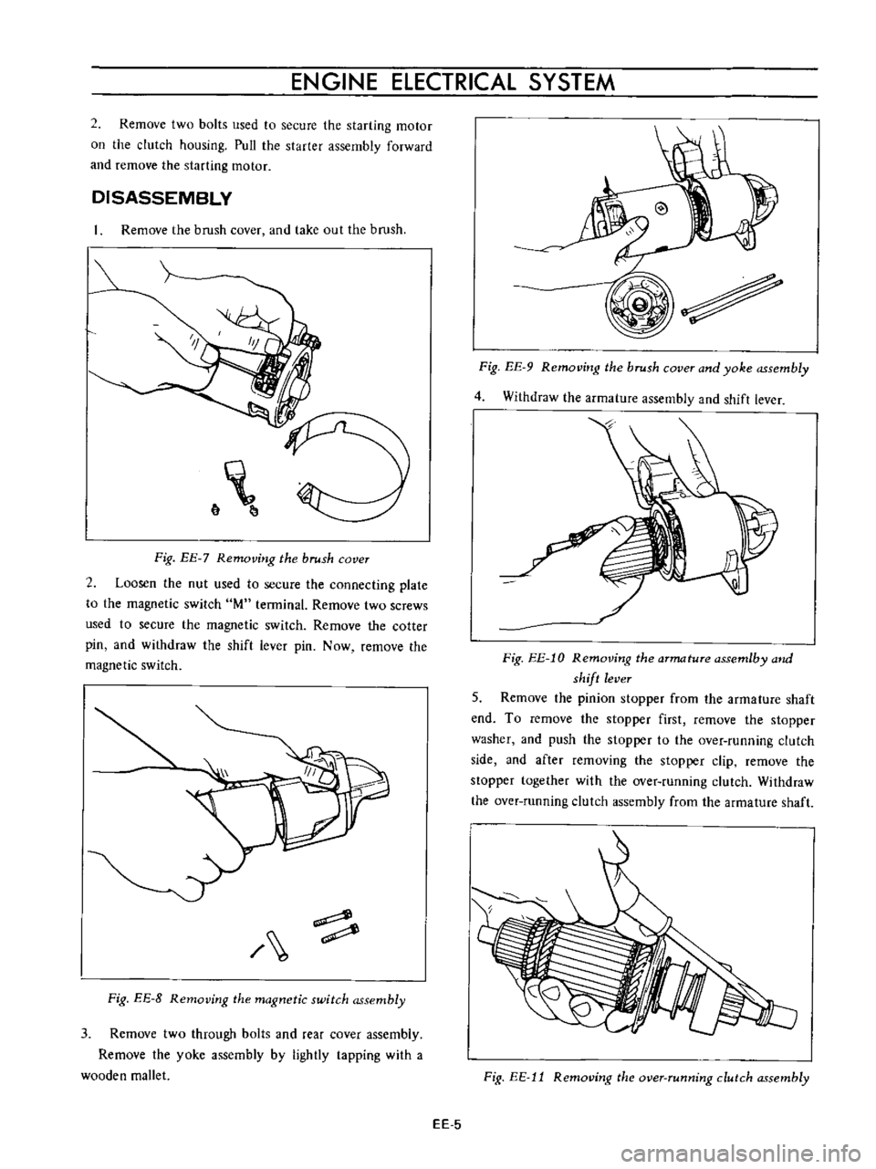
DISASSEMBLY
Remove
the
brush
cover
and
take
out
the
brush
6
Fig
EE
7
Removing
the
brush
cover
2
Loosen
the
nut
used
to
secure
the
connecting
plate
to
the
magnetic
switch
M
terminal
Remove
two
screws
used
to
secure
the
magnetic
switch
Remove
the
cotter
pin
and
withdraw
the
shift
lever
pin
Now
remove
the
magnetic
switch
Fig
EE
8
Removing
the
magnetic
switch
assembly
3
Remove
two
through
bolts
and
rear
cover
assembly
Remove
the
yoke
assembly
by
lightly
tapping
with
a
wooden
mallet
Fig
EE
9
Removing
the
brush
cover
and
yoke
assembly
4
Withdraw
the
armature
assembly
and
shift
lever
Fig
EE
l0
Removing
the
armature
assemlby
and
shift
lever
5
Remove
the
pinion
stopper
from
the
armature
shaft
end
To
remove
the
stopper
first
remove
the
stopper
washer
and
push
the
stopper
to
the
over
running
clutch
side
and
after
removing
the
stopper
clip
remove
the
stopper
together
with
the
over
running
clutch
Withdraw
the
over
running
clutch
assembly
from
the
armature
shaft
Fig
EE
11
Removing
the
over
running
clutch
assembly
EE
5
Page 426 of 513

ENGINE
CLEANING
AND
INSPECTION
Clean
all
disassembled
parts
Be
careful
not
to
use
grease
dissolving
solvent
for
cleaning
of
the
over
running
clutch
armature
assembly
magnetic
switch
assembly
and
field
coils
since
solvent
dissolves
grease
packed
in
the
clutch
mechanism
and
damages
the
coils
or
insulators
Check
them
for
damage
or
excessive
wear
Replace
them
as
required
Terminal
Check
the
terminal
for
damage
and
wear
and
replace
if
necessary
Field
coil
Check
the
field
coil
for
insulation
If
the
coil
insulator
is
damaged
or
worn
replace
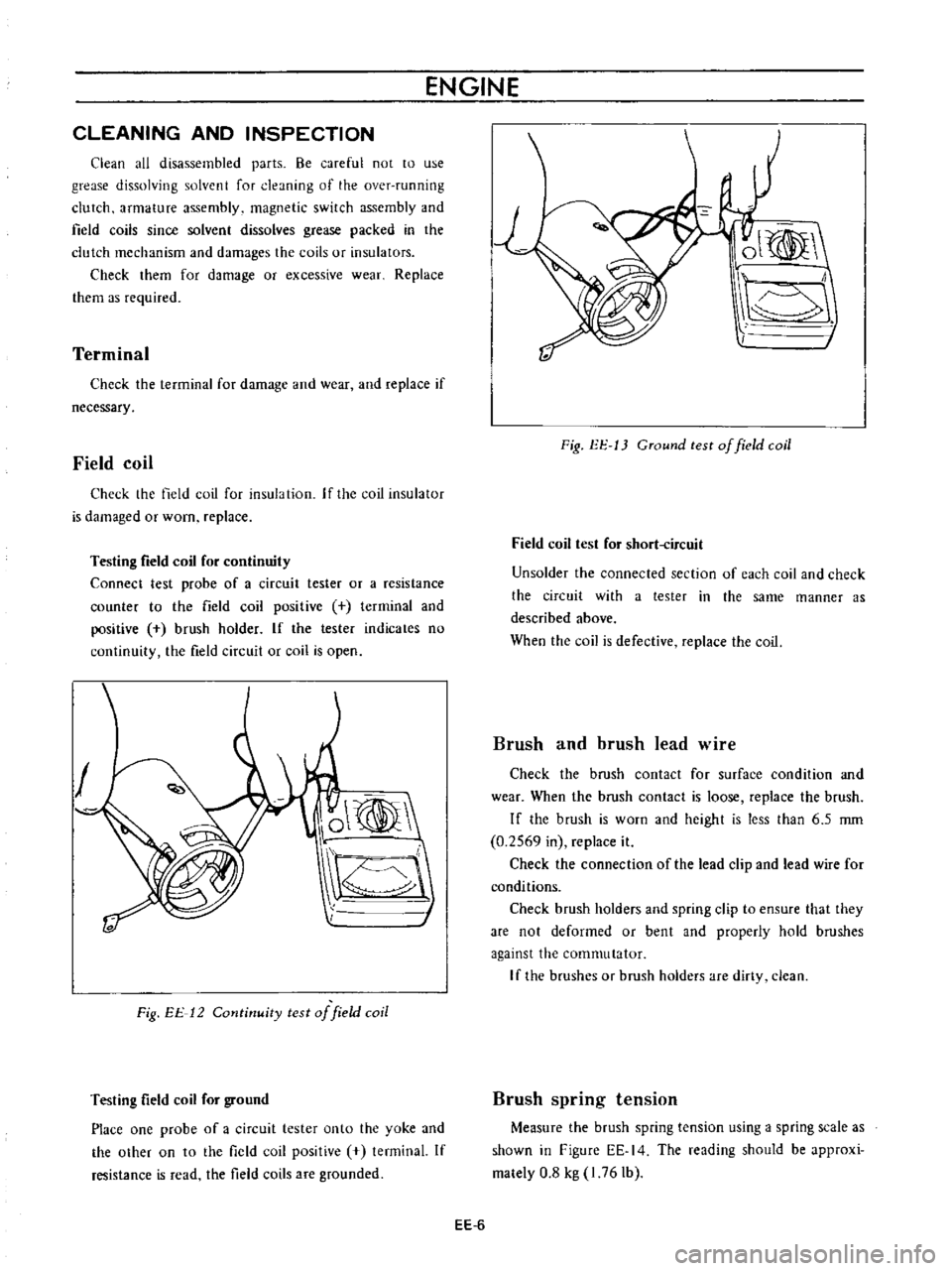
Testing
field
coil
for
continuity
Connect
test
probe
of
a
circuit
tester
or
a
resistance
counter
to
the
field
coil
positive
terminal
and
positive
brush
holder
If
the
tester
indicates
no
continuity
the
field
circuit
or
coil
is
open
O
Fig
EE
12
Cotltinuity
test
of
field
coil
Testing
field
coil
for
ground
Place
one
probe
of
a
circuit
tester
onto
the
yoke
and
the
othef
on
to
the
field
coil
positive
tenninal
If
resistance
is
read
the
field
coils
are
grounded
ol
I
Fig
EE
13
CTound
test
of
field
coil
Field
coil
test
for
short
ircuit
Un
solder
the
connected
section
of
each
coil
and
check
the
circuit
with
a
tester
in
the
same
manner
as
described
above
When
the
coil
is
defective
replace
the
coil
Brush
and
brush
lead
wire
Check
the
brush
contact
for
surface
condition
and
wear
When
the
brush
contact
is
loose
replace
the
brush
If
the
brush
is
worn
and
height
is
less
than
6
5
rom
0
2569
in
replace
it
Check
the
connection
of
the
lead
clip
and
lead
wire
for
conditions
Check
brush
holders
and
spring
clip
to
ensure
that
they
are
not
deformed
or
bent
and
properly
hold
brushes
against
the
commutator
If
the
brushes
Of
brush
holders
are
dirty
clean
Brush
spring
tension
Measure
the
brush
spring
tension
using
a
spring
scale
as
shown
in
Figure
EE
14
The
reading
should
be
approxi
mately
0
8
kg
I
76
Ib
EE
6
Page 427 of 513

ENGINE
ElECTRICAL
SYSTEM
l
J
r
@
V
I
Fig
EE
14
Inspection
of
brush
spring
pressure
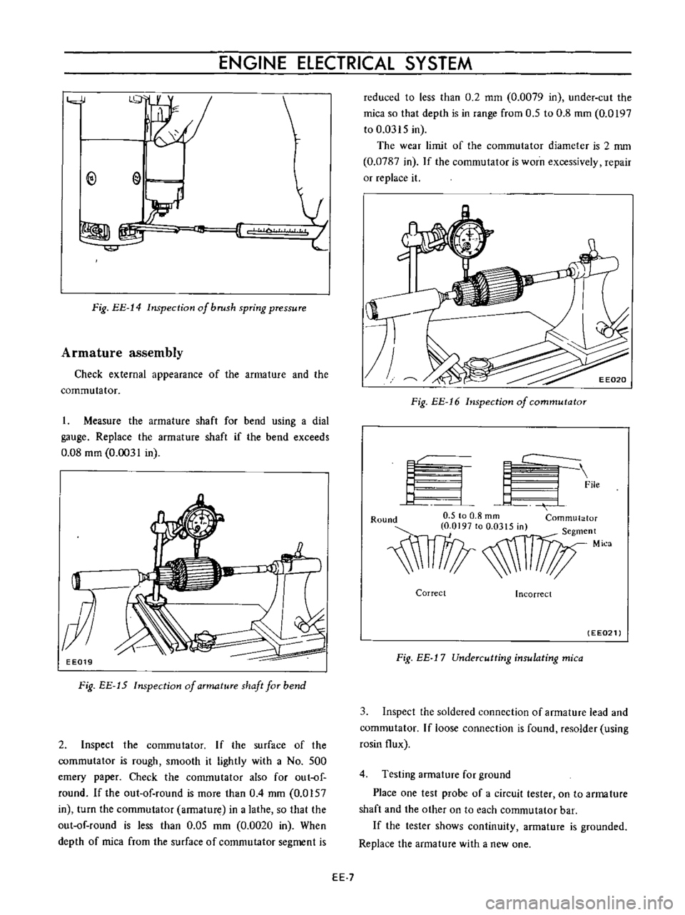
Armature
assembly
Check
external
appearance
of
the
armature
and
the
commutator
I
Measure
the
armature
shaft
for
bend
using
a
dial
gauge
Replace
the
armature
shaft
if
the
bend
exceeds
0
08
mm
0
0031
in
EE019
Fig
EE
15
Inspection
of
aTmatuTe
shaft
faT
bend
2
Inspect
the
commutator
If
the
surface
of
the
commutator
is
rough
smooth
it
lightly
with
a
No
500
emery
paper
Check
the
commutator
also
for
out
of
round
Ifthe
out
of
round
is
more
than
0
4
mm
0
0157
in
turn
the
commutator
armature
in
a
lathe
so
that
the
out
of
round
is
less
than
0
05
mm
0
0020
in
When
depth
of
mica
from
the
surface
of
commutator
segment
is
reduced
to
less
than
0
2
mm
0
0079
in
under
cut
the
mica
so
that
depth
is
in
range
from
0
5
to
0
8
mm
0
0197
to
0
0315
in
The
wear
limit
of
the
commutator
diameter
is
2
nun
0
0787
in
If
the
commutator
is
worn
excessively
repair
or
replace
it
Fig
EE
16
Inspection
of
commutator
f
L
I
C
9
File
4
J
Round
0
5
to
0
8
rom
Commutator
O
OI97tOO
0315m
S
t
egmen
1l1
Mica
Correct
Incorrect
EE021
Fig
EE
j
7
Undercutting
insulating
mica
3
Inspect
the
soldered
connection
of
armature
lead
and
commutator
If
loose
connection
is
found
resolder
using
rosin
flux
4
Testing
armature
for
ground
Place
one
test
probe
of
a
circuit
tester
on
to
arma
ture
shaft
and
the
other
on
to
each
commutator
bar
If
the
tester
shows
continuity
armature
is
grounded
Replace
the
armature
with
a
new
one
EE
7
Page 428 of 513

ENGINE
EE022
Fig
EE
18
Ground
test
of
armature
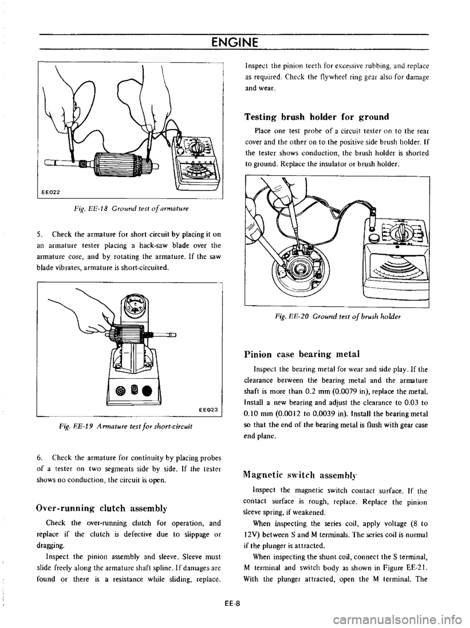
5
Check
the
armature
for
short
circuit
by
placing
it
on
an
armature
tester
placing
a
hack
saw
blade
over
the
armature
core
and
by
rotating
the
armature
If
the
saw
blade
vibrates
armature
is
short
circuited
EE023
Fig
EE
19
4
rmature
test
for
short
circuit
6
Check
the
armature
for
continuity
by
placing
probes
of
a
tester
on
two
segments
side
by
side
If
the
tester
shows
no
conduction
the
circuit
is
open
Over
runnmg
clutch
assembly
Check
the
over
running
clutch
for
operation
and
replace
if
the
clutch
is
defective
due
to
slippage
or
dragging
Inspect
the
pinion
assembly
and
sleeve
Slceve
must
slide
freely
along
the
armature
shaft
spline
I
f
damages
are
found
or
there
is
a
resistance
while
sliding
replace
Inspect
the
pinion
teeth
for
excessive
rubbing
and
replace
as
required
Check
the
flywheel
ring
gear
also
for
damage
and
wear
Testing
brush
holder
for
ground
Place
one
test
probe
of
a
circuit
tester
on
to
the
rear
cover
and
the
other
on
to
the
positive
side
brush
holder
If
the
tester
shows
conduction
the
brush
holdcr
is
shorted
to
ground
Replace
the
insulator
or
brush
holder
od
l
Fig
EE
20
GTound
test
of
bTush
holder
Pinion
case
bearing
metal
Inspect
the
bearing
metal
for
wear
and
sidc
play
If
the
clearance
between
the
bearing
metal
and
the
arma
ture
shaft
is
mOTe
than
0
2
mm
0
0079
in
replace
the
metal
Install
a
new
bearing
and
adjust
the
clearance
to
0
03
to
0
10
mm
0
0012
to
0
0039
in
Install
the
bearing
metal
so
that
the
end
of
the
bearing
metal
is
flush
with
gear
case
end
plane
Magnetic
switch
assembly
Inspect
the
magnetic
switch
contact
surface
If
the
contact
surface
is
rough
replace
Replace
the
pinion
sleeve
spring
if
weakened
When
inspecting
the
series
coil
apply
voltagc
8
to
12V
between
Sand
M
terminals
The
series
coil
is
normal
if
the
plunger
is
attracted
When
inspecting
the
shunt
coil
connect
the
S
terminal
M
terminal
and
switch
body
as
shown
in
Figure
EE
21
With
the
plunger
attracted
open
the
M
terminal
The
EE
S
Page 429 of 513

ENGINE
ElECTRICAL
SYSTEM
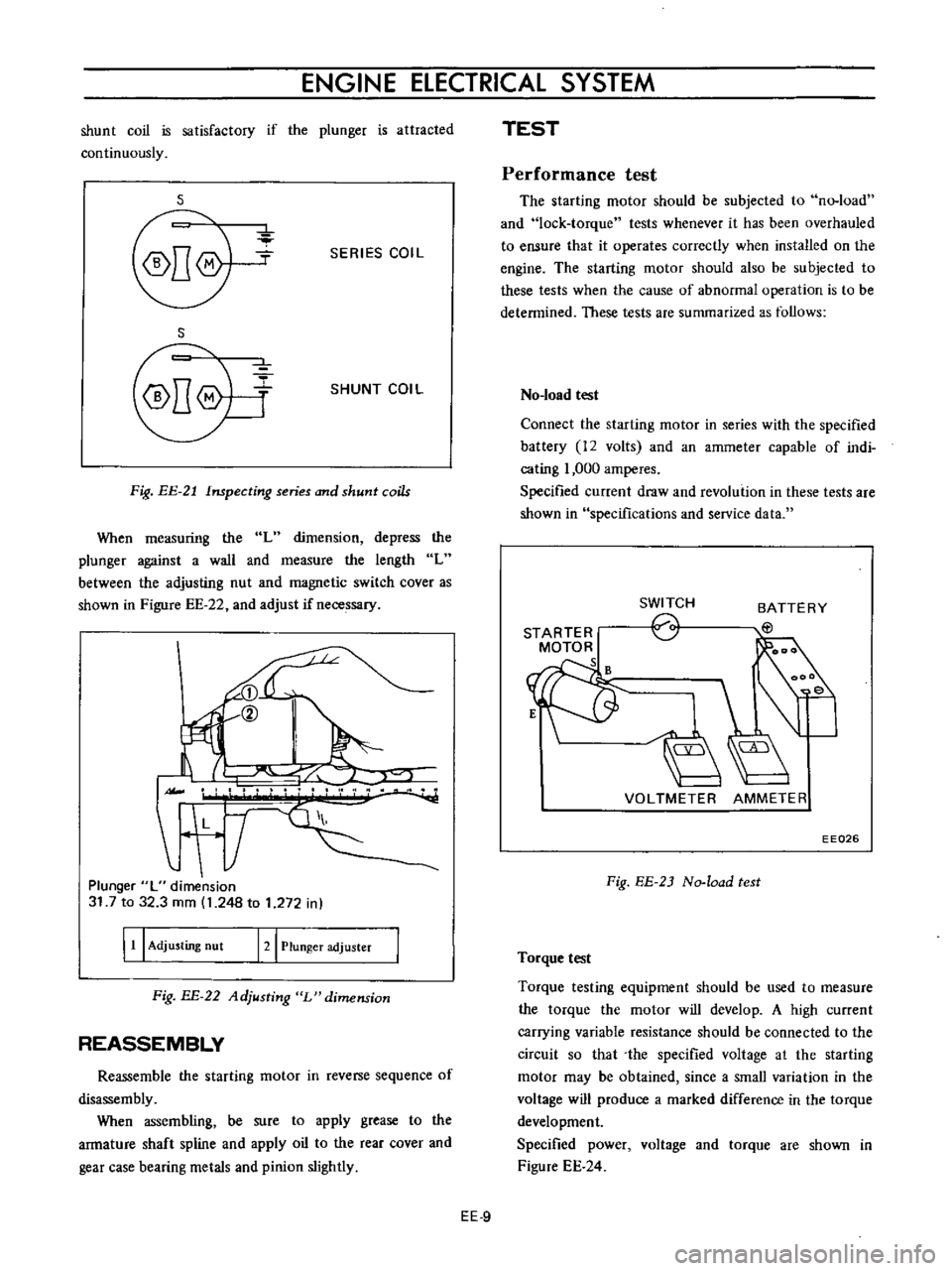
shunt
coil
is
satisfactory
if
the
plunger
is
attracted
continuously
s
SERIES
COIL
S
SHUNT
COIL
Fig
EE
21
Inspecting
series
and
shunt
coils
When
measuring
the
L
dimension
depress
the
plunger
against
a
wall
and
measure
the
length
L
between
the
adjusting
nut
and
magnetic
switch
cover
as
shown
in
Figure
EE
22
and
adjust
if
necessary
II
L
T
Plunger
L
dimension
31
7
to
32
3
mm
1
248
to
1
272
in
I
11
I
Adjusting
nut
121
Plunger
adjuster
Fig
BE
22
Adjusting
L
dimension
REASSEMBLY
Reassemble
the
starting
motor
in
reverse
sequence
of
disassembly
When
assembling
be
sure
to
apply
grease
to
the
armature
shaft
spline
and
apply
oil
to
the
rear
cover
and
gear
case
bearing
metals
and
pinion
slightly
TEST
Performance
test
The
starting
motor
should
be
subjected
to
no
load
and
lock
torque
tests
whenever
it
has
been
overhauled
to
ensure
that
it
operates
correctly
when
installed
on
the
engine
The
starting
motor
should
also
be
subjected
to
these
tests
when
the
cause
of
abnormal
operation
is
to
be
determined
These
tests
are
summarized
as
follows
No
load
test
Connect
the
starting
motor
in
series
with
the
specified
battery
12
volts
and
an
ammeter
capable
of
indi
cating
1
000
amperes
Specified
current
draw
and
revolution
in
these
tests
are
shown
in
specifications
and
service
data
STARTER
MOTOR
s
SWITCH
o
BATTERY
EtJ
VOLTMETER
AMMETER
EE026
Fig
EE
2J
No
load
test
Torque
test
Torque
testing
equipment
should
be
used
to
measure
the
torque
the
motor
will
develop
A
high
current
carrying
variable
resistance
should
be
connected
to
the
circuit
so
that
the
specified
voltage
at
the
starting
motor
may
be
obtained
since
a
small
variation
in
the
voltage
will
produce
a
marked
difference
in
the
torque
development
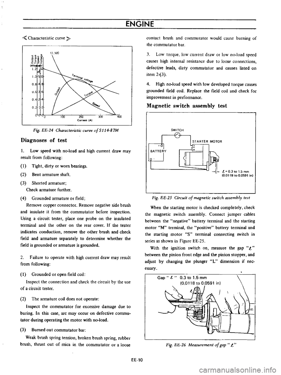
Specified
power
voltage
and
torque
are
shown
in
Figure
EE
24
EE
9
Page 430 of 513

ENGINE
Characteristic
curve
i
8
s
l00
0
OJ
m
v
1
2
1
0
tc
0
8
E
u
6
E
o
4
0
2
L
c
0
00
J
300
Current
IAI
Fig
EE
24
Characteristic
curve
of
S
114
B
7M
Diagnoses
of
test
1
Low
speed
with
no
load
and
high
current
draw
may
result
from
following
1
Tight
dirty
or
worn
bearings
2
Bent
armature
shaft
3
Shorted
armature
Check
armature
further
4
Grounded
armature
or
field
Remove
copper
connector
Remove
negative
side
brush
and
insulate
it
from
the
commutator
before
inspection
Using
a
circuit
tester
place
one
probe
on
the
insulated
terminal
and
the
other
on
the
rear
cover
If
the
tester
indicates
conduction
remove
the
other
brush
and
check
field
and
armature
separately
to
determine
whether
the
field
is
grounded
or
armature
is
grounded
2
Failure
to
operate
with
high
current
draw
may
result
from
following
I
Grounded
or
open
field
coil
Inspect
the
connection
and
check
the
circuit
by
the
use
of
a
circuit
tester
2
The
armature
coil
does
not
operate
Inspect
the
commutator
for
excessive
damage
due
to
buring
In
this
case
arc
may
occur
on
defective
commu
tator
during
operating
the
motor
with
no
load
3
Burned
out
commutator
bar
Weak
brush
spring
tension
broken
brush
spring
rubber
brush
thrust
out
of
mica
in
the
commutator
or
a
loose
EE
10
contact
brush
and
commutator
would
cause
burning
of
the
commutator
bar
3
Low
torque
low
current
draw
or
low
no
load
speed
causes
high
internal
resistance
due
to
loose
connections
defective
leads
dirty
commutator
and
causes
listed
on
item
2
3
4
High
no
load
speed
with
low
developed
torque
causes
grounded
field
coil
Replace
the
field
coil
and
check
for
improvement
in
performance
Magnetic
switch
assembly
test
SWITCH
STARTER
MOTOR
61
1u
i
T
0
0118
to
0
0591
n
Fig
EE
25
Circuit
of
magnetic
switch
assembly
test
When
the
starting
motor
is
checked
completely
check
the
magnetic
switch
assembly
Connect
jumper
cables
between
the
negative
battery
terminal
and
the
starting
motor
lM
terminal
the
positive
battery
terminal
and
the
starting
motor
S
terminal
connecting
switch
in
series
as
shown
in
Figure
EE
25
With
the
ignition
switch
on
measure
the
gap
I
between
the
pinion
front
edge
and
the
pinion
stopper
and
adjust
by
changing
the
plunger
L
dimension
if
nec
essary
Gap
l
0
3
to
1
5
mm
0
0118
to
0
0591
in
l
Fig
EE
26
Measurement
of
gap
L
Page 431 of 513

ENGINE
ElECTRICAL
SYSTEM
SPECIFICATIONS
AND
SERVICE
DATA
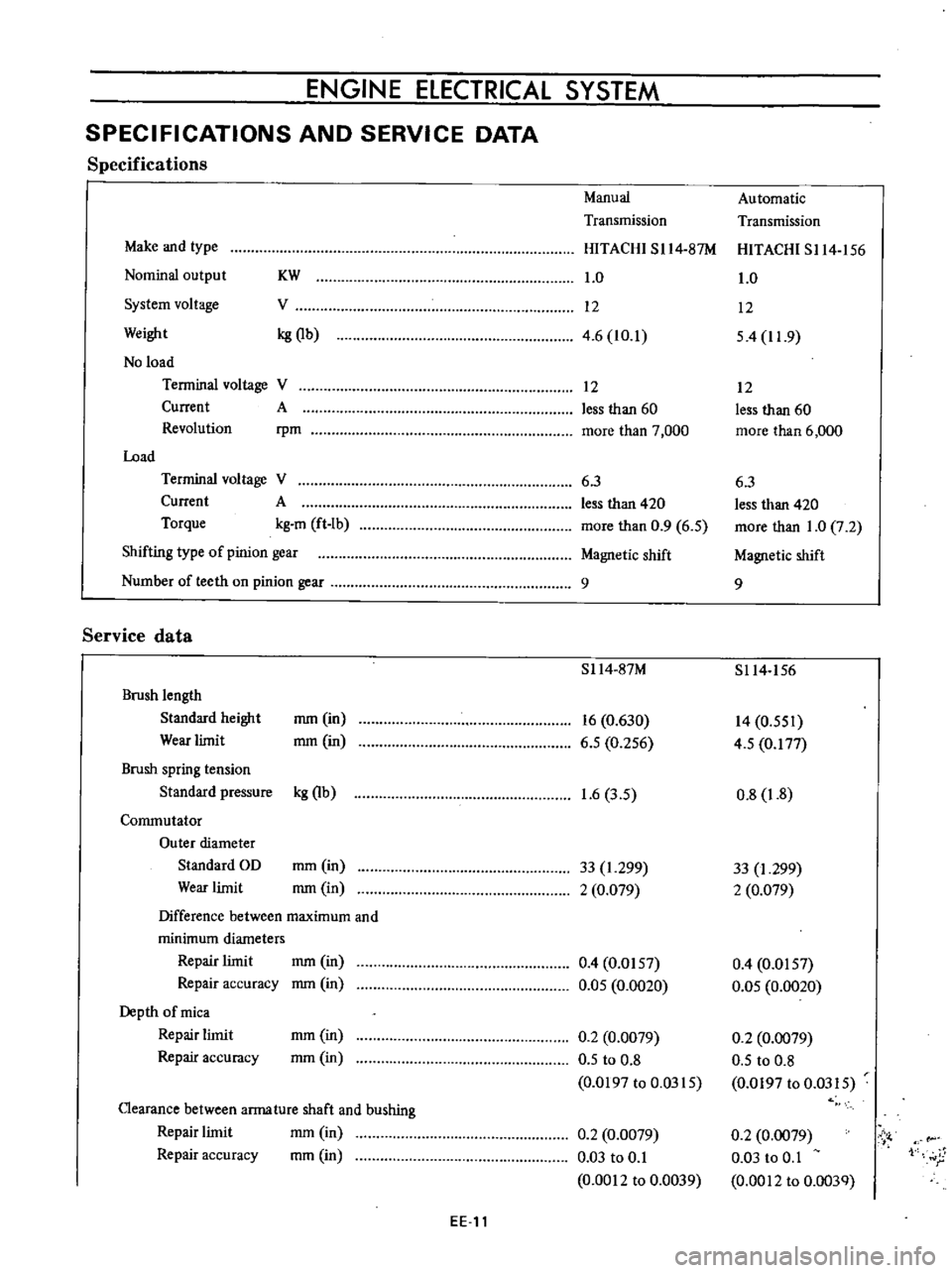
Specifications
Manual
Automatic
Transmission
Transmission
Make
and
type
HITACHI
SI14
87M
HITACHI
S114
156
Nominal
output
KW
1
0
1
0
System
voltage
V
12
12
Weight
kg
Qb
4
6
10
1
54
11
9
No
load
Terminal
voltage
V
12
12
Current
A
less
than
60
less
than
60
Revolution
rpm
more
than
7
000
more
than
6
000
Load
Terminal
voltage
V
6
3
6
3
Current
A
less
than
420
less
than
420
Torque
kg
m
ft
Ib
more
than
0
9
6
5
more
than
1
0
7
2
Shifting
type
of
pinion
gear
Magnetic
shift
Magnetic
shift
Number
of
teeth
on
pinion
gear
9
9
Service
data
S114
87M
S114
156
Brush
length
Standard
height
mm
in
16
0
630
14
0
551
Wear
limit
mm
in
6
5
0
256
4
5
0
177
Brush
spring
tension
Standard
pressure
kg
Qb
1
6
3
5
0
8
1
8
Commutator
Outer
diameter
Standard
OD
mm
in
33
1
299
33
I
299
Wear
limit
mm
in
2
0
079
2
0
079
Difference
between
maximum
and
minimum
diameters
Repair
limit
mm
in
0
4
0
0157
0
4
0
0157
Repair
accuracy
mm
in
0
05
0
0020
0
05
0
0020
Depth
of
mica
Repair
limit
mm
in
0
2
0
0079
0
2
0
0079
Repair
accuracy
mm
in
0
5
to
0
8
0
5
to
0
8
0
0197
to
0
0315
0
0197
to
0
0315
Clearance
between
arma
ture
shaft
and
bushing
mm
in
Repair
limit
0
2
0
0079
0
2
0
0079
Vi
Repair
accuracy
mm
in
0
03
to
0
1
0
03
to
0
1
1
r
0
0012
to
0
0039
0
0012
to
0
003Q
EE
11
Page 432 of 513

ENGINE
Arma
ture
shaft
Outer
diameter
Pinion
side
mm
in
12
950
to
12
968
0
5082
to
0
5105
11
450
to
II
468
0
4507
to
0
4515
0
1
0
0039
0
08
0
0031
Rear
end
mm
in
Wear
limit
Bend
limit
mm
in
mm
in
Gap
1
between
the
pinion
front
edge
and
the
pinion
stopper
mm
in
0
3
to
1
5
0
0118
to
0
0591
Magnetic
switch
Coil
resistance
Series
cuil
Q
Shunt
coil
n
Plunger
L
dimension
mm
in
0
3
at
20De
68UF
0
9
at
ooe
680F
317t032
3
l
248
to
1
272
TROUBLE
DIAGNOSES
AND
CORRECTIONS
12
950
to
12
968
0
5082
to
0
5105
11
450
to
II
468
0
4507
to
0
4515
l
0
1
0
0039
0
08
0
0031
0
3
to
1
5
0
0118
to
0
0591
0
3
at
20De
680Fl
0
9
at
200e
680F
317
to
32
3
l
248
to
I
272
Troubles
Trouble
location
Causes
Remedies
Starting
motor
will
not
operate
No
magnetic
switch
Battery
Defective
battery
Replace
battery
operating
sound
Over
discharging
Measure
specific
gravity
of
e
Ie
ctrolyte
and
ch
lrge
or
replace
the
battery
Ignition
switch
Defective
contact
Correct
or
replace
ig
nition
switch
Wiring
Faulty
starting
motor
grounding
Correct
Faulty
battery
grounding
Correct
Broken
or
disconnected
cable
Correct
or
replace
EE
12