1973 DATSUN B110 recommended oil
[x] Cancel search: recommended oilPage 38 of 513

Fig
A
T
49
Torque
converter
aligning
cut
3
When
connecting
torque
con
verter
to
transmission
measure
dis
tance
A
to
be
certain
that
they
are
correctly
assembled
See
Figure
AT
50
Distance
A
More
than
16
5
IllIll
0
650
in
A
AT117
Fig
A
T
50
Installing
torque
converter
CHASSIS
4
Bolt
converter
to
drive
plate
Tightening
torque
0
8
to
1
0
kg
Ill
5
8
to
7
2
ft
Ib
Note
Align
chalk
marks
painted
a
cross
both
parts
during
disas
sembling
processes
5
After
converter
is
installed
rotate
crankshaft
several
turns
and
check
to
be
sure
that
transmission
rotates
freely
without
binding
6
Pour
recommended
automatic
transmission
fluid
up
to
correct
level
through
oil
charge
pipe
7
Connect
manual
lever
to
shift
rod
Operation
should
be
carried
out
with
manual
and
selector
levers
in
N
8
Connect
inhibitor
switch
wires
Notes
a
Refer
to
covering
topic
under
Checking
and
adjusting
inhibitor
switch
on
page
AT
51
b
Inspect
and
adjust
switch
as
above
whenever
it
has
to
be
removed
for
service
9
Check
inhibitor
switch
for
op
eration
AT
34
Starter
should
be
brought
into
op
eration
only
when
selector
lever
is
in
P
and
N
positions
it
should
not
be
started
when
lever
is
in
D
2
1
and
R
positions
Back
up
lamp
should
also
light
when
selector
lever
is
placed
in
R
position
10
Check
level
of
oil
in
transmis
sion
For
detailed
procedure
see
page
AT
49
II
Move
selector
lever
through
all
positions
to
be
sure
that
transmission
operates
correctly
With
hand
brake
applied
rotate
engine
at
idling
Without
disturbing
the
above
setting
move
selector
lever
through
N
to
D
to
2
to
I
and
to
R
A
slight
shock
should
be
felt
by
hand
gripping
selector
each
time
transmission
is
shifted
Note
See
page
AT
50
for
checking
enigne
idling
12
Check
to
be
sure
that
line
pres
sure
is
correct
To
do
this
refer
to
relative
topic
under
Testing
line
pres
sure
on
page
AT
53
13
Perform
stall
test
as
per
the
instructions
on
page
AT
51
Page 49 of 513

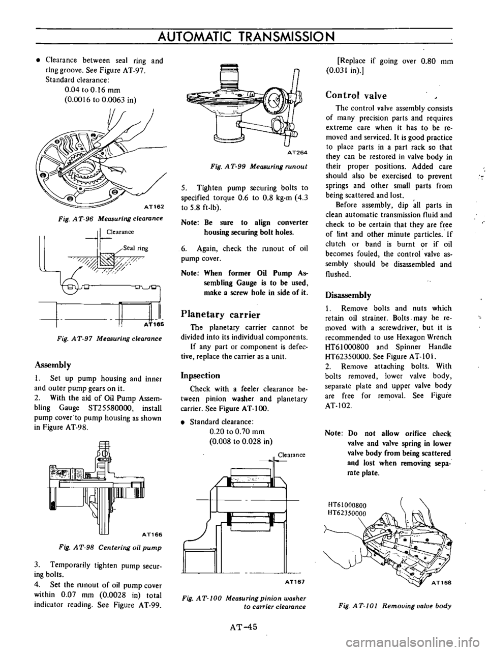
Clearance
between
seal
ring
and
ring
groove
See
Figure
AT
97
Standard
clearance
0
04toO
16mm
0
0016
to
0
0063
in
AT162
Fig
A
T
96
Measuring
clearance
I
earance
I
Seal
rIng
0d
t
AT185
II
Fig
AT
97
Measuring
clearance
Assembly
1
Set
up
pump
housing
and
inner
and
outer
pump
gears
on
it
2
With
the
aid
of
Oil
Pump
Assem
bling
Gauge
ST255800oo
install
pump
cover
to
pump
housing
as
shown
in
Figure
AT
98
lnnrr
i
rnl
l
AT166
Fig
A
T
98
Centering
oil
pump
3
Temporarily
tighten
pump
secur
ing
bolts
4
Set
the
runout
of
oil
pump
cover
within
0
07
mm
0
0028
in
total
indicator
reading
See
Figure
A
T
99
AUTOMATIC
TRANSMISSION
AT264
Fig
A
T
99
Measuring
run
out
5
Tighten
pump
securing
bolts
to
specified
torque
0
6
to
0
8
kg
m
4
3
to
5
8
ft
Ib
Note
Be
sure
to
align
converter
housing
securing
bolt
holes
6
Again
check
the
runout
of
oil
pump
cover
Note
When
former
Oil
Pump
As
sembling
Gauge
is
to
be
used
make
a
screw
hole
in
side
of
it
Planetary
carrier
The
planetary
carrier
cannot
be
divided
into
its
individual
components
If
any
part
or
component
is
defec
tive
replace
the
carrier
as
a
unit
Inpsection
Check
with
a
feeler
clearance
be
tween
pinion
washer
and
planetary
carrier
See
Figure
AT
100
Standard
clearance
0
20
to
0
70
mm
0
008
to
0
028
in
Clearance
I
LJ
b
II
I
AT161
Fig
AT
100
Mea
uring
pinion
washer
to
carrier
clearance
AT
45
Replace
if
going
over
0
80
mm
0
031
in
Control
valve
The
control
valve
assembly
consists
of
many
precision
parts
and
requires
extreme
care
when
it
has
to
be
re
moved
and
serviced
It
is
good
practice
to
place
parts
in
a
part
rack
so
that
they
can
be
restored
in
valve
body
in
their
proper
positions
Added
care
should
also
be
exercised
to
prevent
springs
and
other
small
parts
from
being
scattered
and
lost
Before
assembly
dip
all
parts
in
clean
automatic
transmission
nuid
and
check
to
be
certain
that
they
are
free
of
lint
and
other
minute
particles
If
clutch
or
band
is
burnt
or
if
oil
becomes
fouled
the
control
valve
as
sembly
should
be
disassembled
and
flushed
Disassembly
1
Remove
bolts
and
nuts
which
retain
oil
strainer
Bolts
may
be
re
moved
with
a
screwdriver
but
it
is
recommended
to
use
Hexagon
Wrench
HT61000800
and
Spinner
Handle
HT62350000
See
Figure
AT
10
I
2
Remove
attaching
bolts
With
bolts
removed
lower
valve
body
separate
plate
and
upper
valve
body
are
free
for
removal
See
Figure
AT
102
Note
Do
not
allow
orifice
check
valve
and
valve
spring
in
lower
valve
body
from
being
scattered
and
lost
when
removing
sepa
rate
plate
HT61000BOO
HT62350000
Fig
AT
101
Removing
valve
body
Page 135 of 513

BRAKE
CYLINDER
SIDE
PISTON
SIDE
COMPR
ESSION
DECOMPRESSION
Movement
exceeding
the
elastic
displacement
is
released
with
slipping
on
the
seal
surface
Returns
in
elastic
displacement
of
the
seal
Fig
BR
21
Piston
seal
automatic
adjusting
operation
Brake
pad
Replacement
1
Jack
up
front
unit
of
the
vehicle
and
remove
lhe
front
wheeL
2
Remove
clip
from
the
retaining
pin
and
supporting
the
brake
pad
remove
the
retaining
pin
and
coil
spring
I
I
Brake
pad
2
Retaining
pin
I
31
Clip
Fig
BR
22
Removing
retaining
pin
3
Unhook
the
hanger
spring
and
withdraw
the
brake
pad
and
shim
with
a
pair
of
pliers
BR
ll
Fig
HR
2
Withdrawing
brake
pad
and
shim
Note
When
the
brake
pad
is
removed
do
not
depress
the
brake
pedal
or
otherwise
the
piston
will
come
out
Inspection
Clearance
between
the
brake
pad
and
rotor
is
adjusted
automatically
Check
the
brake
pad
for
wear
after
the
first
10
000
km
6
000
miles
driving
and
every
5
000
km
3
000
miles
thereafter
1
Clean
the
brake
pad
with
carbon
tetrachloride
or
gasoline
2
When
oil
and
or
grease
is
heavily
sticked
on
the
pad
or
when
deteriorated
or
deformed
due
to
overheating
replace
the
pad
with
a
new
one
3
When
thickness
of
the
friction
material
pad
is
less
than
1
6
mm
0
0630
in
replace
Replace
when
total
pad
thickness
is
less
than
6
1
mm
0
2402
in
Note
Replace
pads
as
a
set
Replacement
at
only
one
position
may
cause
uneven
brake
effect
It
is
recommended
that
rotation
of
pads
be
made
periodically
4
Check
the
rotor
Refer
to
Rotor
inspection
Reinstallation
1
Clean
the
calipers
and
piston
pad
installing
parts
Note
Do
not
use
mineral
oil
Be
careful
not
to
apply
oil
on
the
rotor
2
Depress
the
piston
into
the
cylinder
so
that
new
pad
can
be
installed
Page 161 of 513

STEERING
DESCRIPTION
The
steering
system
consists
of
recirculating
ball
type
gear
box
and
parallelogram
linkage
These
systems
give
good
response
light
handling
and
utmost
durability
Moreover
the
steering
linkage
is
equipped
with
a
torsion
rubber
system
idler
arm
which
absorbs
shock
from
the
wheel
Check
the
lubricant
of
gear
box
every
10
000
km
6
000
miles
and
replenish
recommended
oil
as
required
The
steering
linkage
should
be
greased
up
with
wheel
bearing
grease
every
50
000
km
30
000
miles
All
necessary
service
procedures
for
the
steering
lock
system
are
described
in
the
BODY
ELECTRICAL
SECTION
of
this
manual
and
therefore
no
instruction
is
given
here
STEERING
CONTENTS
REMOVAL
DISASSEMBL
Y
Ball
nut
assembly
ST
2
ST
3
ST
4
INSPECTION
AND
REPAIR
ASSEMBL
Y
AND
ADJUSTMENT
INSTALLATION
ST
4
ST
5
ST
7
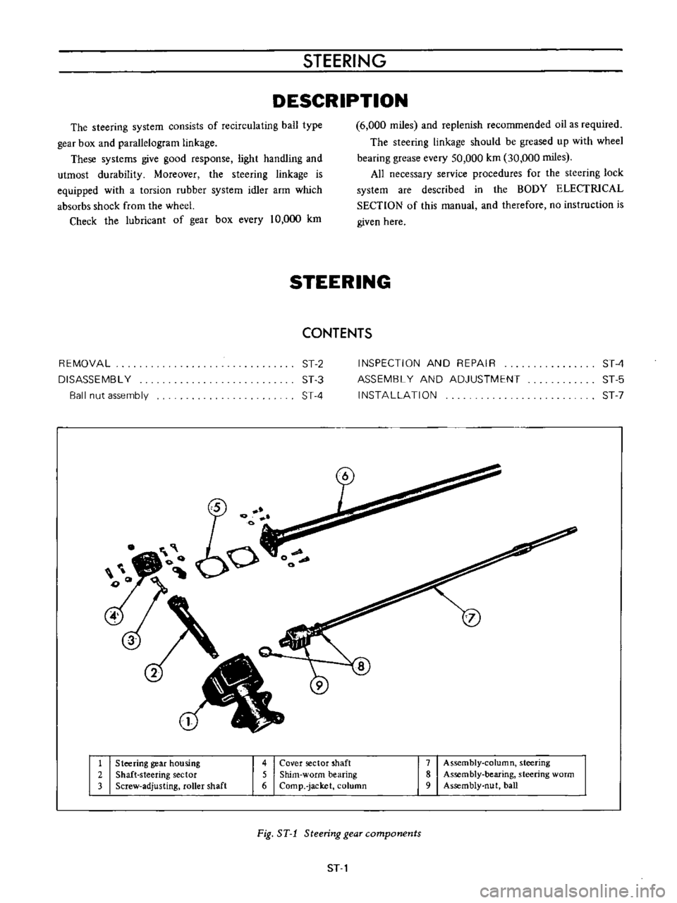
1
Steering
gear
housing
2
Shaft
steering
sector
3
Screw
adjusting
roller
shaft
4
Cover
sector
shaft
5
Shim
worm
bearing
6
Comp
jacket
column
7
Assembly
column
steering
8
Assembly
bearing
steering
worm
9
Assembly
nut
ball
Fig
ST
1
Steering
gear
components
ST
1
Page 216 of 513

Removal
I
t
is
recommended
that
the
door
be
removed
from
the
body
with
the
door
hinges
attached
on
the
door
although
the
door
may
be
removed
from
the
body
with
or
without
the
hinges
attached
on
the
door
Front
door
Remove
the
package
tray
2
Remove
the
door
hinge
service
hole
cover
from
the
dash
side
trim
3
With
the
door
fully
opened
support
the
door
by
applying
a
stand
or
jack
beneath
the
door
so
that
the
door
does
not
drop
off
Note
Apply
a
piece
of
rag
between
the
door
and
stand
so
that
the
door
panel
is
protected
from
damaging
4
Remove
the
door
hinge
installation
bolts
at
the
body
side
by
the
use
of
a
box
wrench
and
remove
the
door
from
the
body
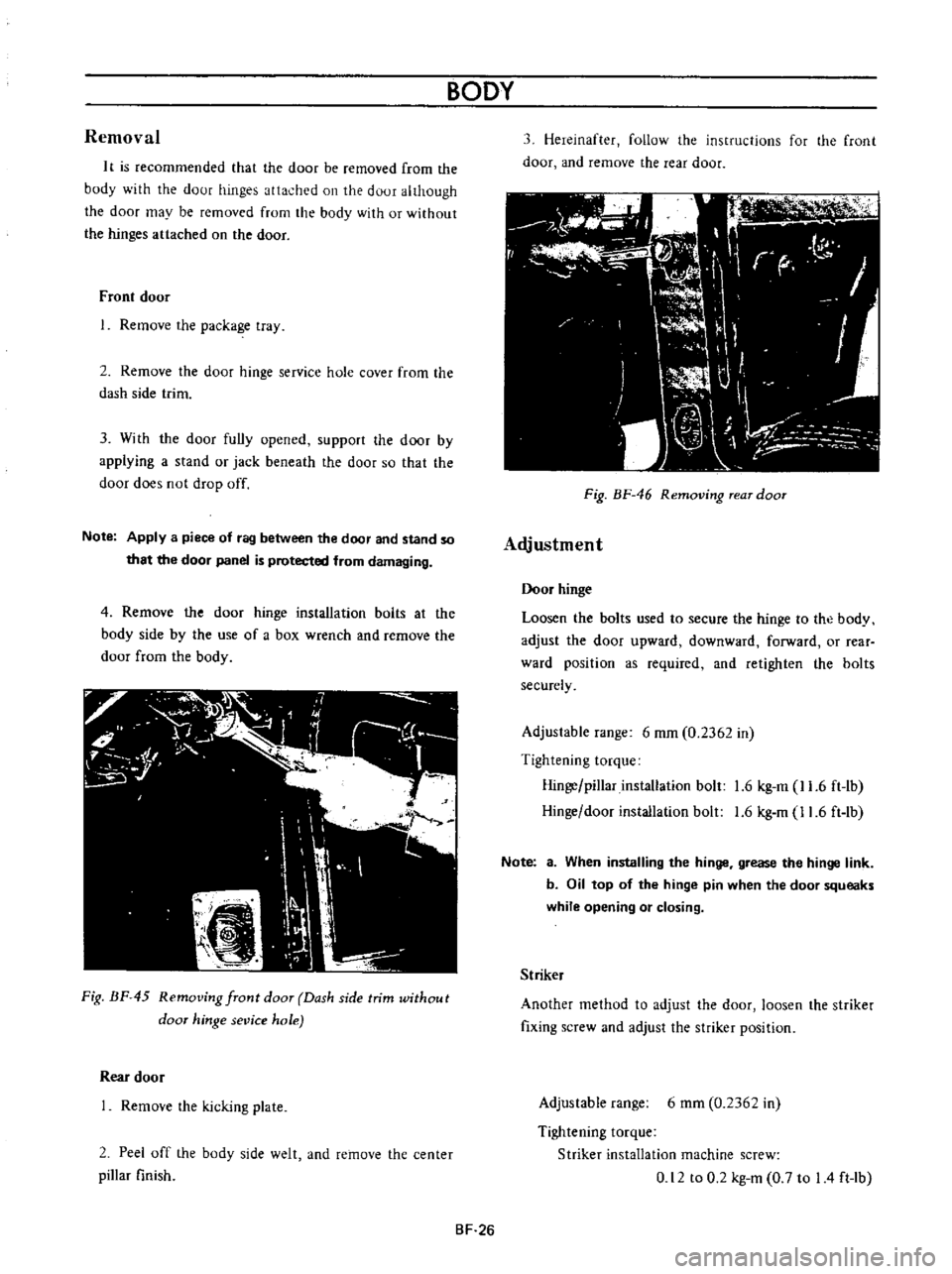
Fig
BF
45
Removing
front
door
Dash
side
trim
without
door
hinge
sevice
hole
Rear
door
Remove
the
kicking
plate
2
Peel
off
the
body
side
welt
and
remove
the
center
pillar
finish
BODY
3
Hereinafter
follow
the
instructions
for
the
front
door
and
remove
the
rear
door
11
I
fl
C
I
r
r
I
W
I
r
I
I
dl
J
Ik
I
h
I
l
i
J
n
Fig
BF
46
Removing
rear
door
Adjustment
Door
hinge
Loosen
the
bolts
used
to
secure
the
hinge
to
the
body
adjust
the
door
upward
downward
forward
or
rear
ward
position
as
required
and
retighten
the
bolts
securely
Adjustable
range
6
mm
0
2362
in
Tightening
torque
Hinge
pillar
installation
bolt
1
6
kg
m
11
6
ft
lb
Hinge
door
installation
bolt
1
6
kg
m
11
6
ft
lb
Note
a
When
installing
the
hinge
grease
the
hinge
link
b
Oil
top
of
the
hinge
pin
when
the
door
squeaks
while
opening
or
closing
Striker
Another
method
to
adjust
the
door
loosen
the
striker
fixing
screw
and
adjust
the
striker
position
Adjustable
range
6
mm
0
2362
in
Tightening
torque
Striker
installation
machine
screw
0
12
to
0
2
kg
m
0
7
to
I
4
ft
lb
BF
26
Page 301 of 513

GENERAL
INFORMATION
steering
wheel
should
be
secured
to
maintain
a
straight
ahead
position
TIE
DOWN
The
front
tie
down
hook
is
used
the
both
front
end
of
tension
rod
Do
not
apply
the
hook
at
the
center
of
tension
rod
or
suspension
member
The
rear
tie
down
hook
is
used
the
both
front
shackle
of
rear
spring
APPROXIMATE
REFILL
CAPACITY
Liter
U
S
A
measure
I
Imp
measure
Sedan
Fuel
tank
Coupe
with
heater
Cooling
system
without
heater
40
L
38
L
4
9
L
4
2
L
2
7
L
0
54
L
1
2
L
5
5
L
0
75
L
0
24
L
Oil
pan
Oilf1lter
Transmission
case
Manual
Automatic
Differential
case
Steering
gear
box
RECOMMENDED
GASOLINE
FUEL
Use
a
no
lead
or
low
lead
gasoline
with
a
minimum
octane
rating
of
87
the
average
of
the
Research
and
1O
gal
8Y
gal
10
gal
8
gal
5
v
qt
4
M
qt
4
Y
6
qt
3
Y
qt
2Ji
qt
2
qt
1
pt
I
pt
2
pt
2
pt
5Ji
qt
4
qt
1
pt
1
pt
pt
pi
Motor
Octane
Numbers
in
the
U
S
When
the
figure
is
based
on
the
Research
Octane
Number
use
a
gasoline
with
a
minimum
octane
rating
of
91
RON
in
Canada
RECOMMENDED
LUBRICANTS
GI
5
r
Page 302 of 513

GENERAL
INFORMATION
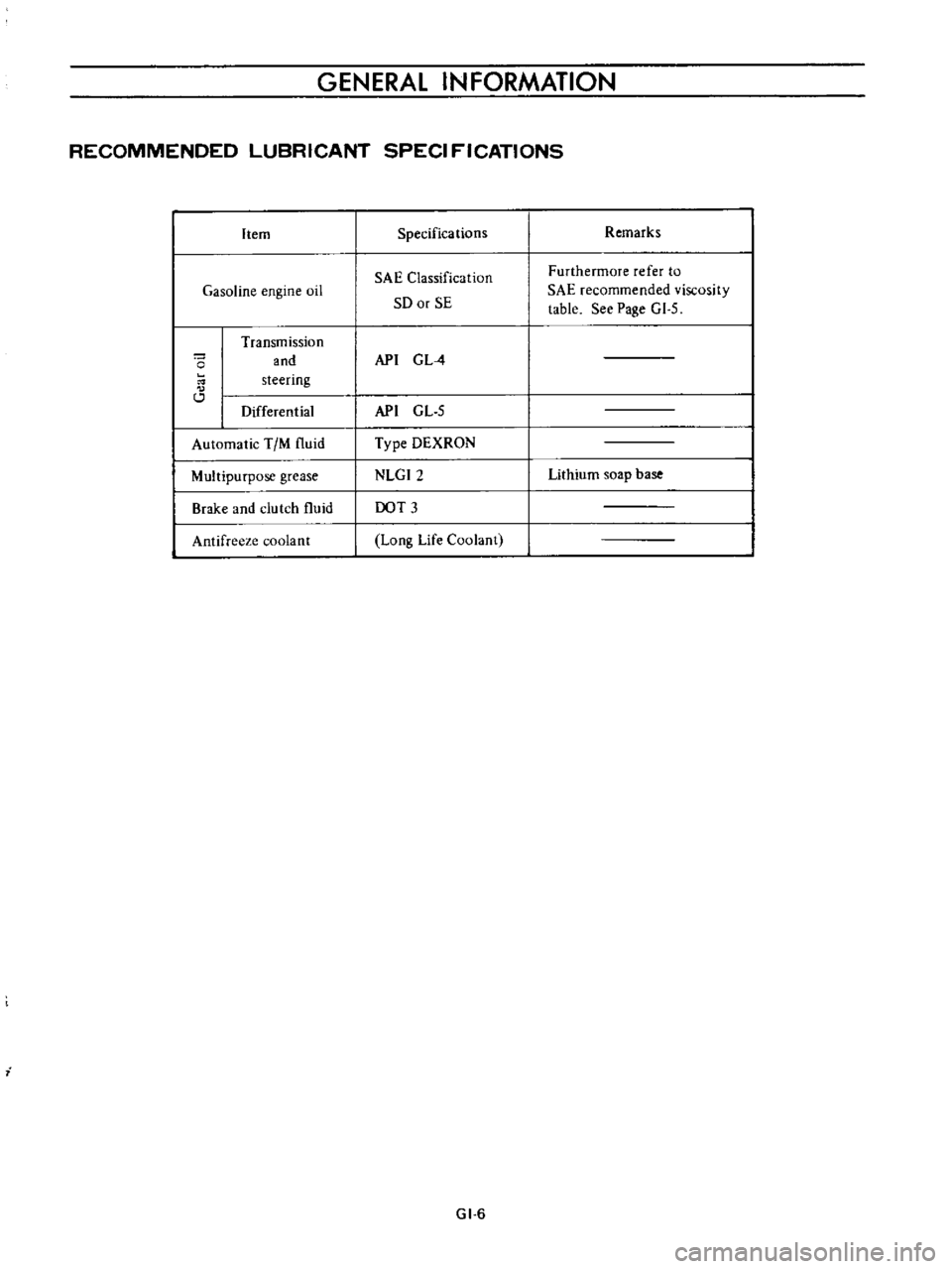
RECOMMENDED
LUBRICANT
SPECI
FICATIONS
Item
Gasoline
engine
oil
o
Transmission
and
steering
Differential
Automatic
TIM
fluid
Multipurpose
grease
Brake
and
clutch
fluid
Antifreeze
coolant
i
Specifications
SAE
Classification
SO
or
SE
API
G
L
4
API
GL
5
Type
DEXRON
NLGI2
DOT
3
Long
Life
Coolant
GI
6
Remarks
Furthermore
refer
to
SAE
recommended
viscosity
table
See
Page
GI
5
Lithium
soap
base