1973 DATSUN B110 maintenance
[x] Cancel search: maintenancePage 154 of 513
DESCRIPTION
MAINTENANCE
AND
SERVICE
Tire
inflation
Tubeless
tire
repair
Wheel
repair
Wear
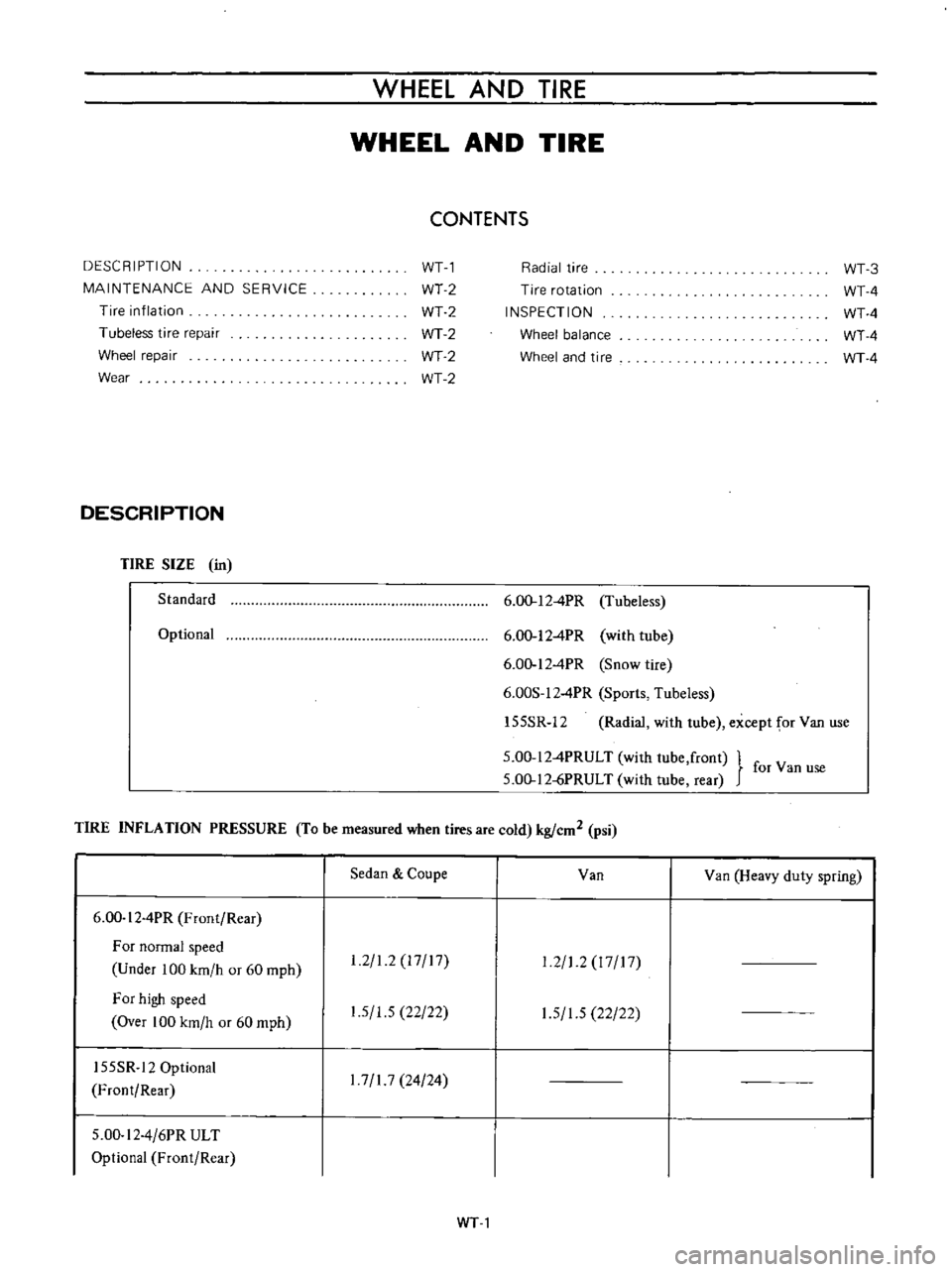
DESCRIPTION
TIRE
SIZE
in
Standard
Optional
WHEEL
AND
TIRE
WHEEL
AND
TIRE
CONTENTS
WTl
WT2
WT2
WT2
WT2
WT2
Radial
tire
Tire
rotation
INSPECTION
Wheel
balance
Wheel
and
tire
6
00
12
4PR
Tubeless
6
00
12
4PR
with
tube
6
00
12
4PR
Snow
tire
6
00S
12
4PR
Sports
Tubeless
155SR
12
Radial
with
tube
except
for
Van
use
5
00
12
4PRULT
with
lube
front
for
Van
use
5
00
12
jPRULT
with
tube
rear
TIRE
INFLATION
PRESSURE
To
be
measured
when
tires
are
cold
kg
cm2
psi
6
00
I
2
4PR
Front
Rear
For
normal
speed
Under
100
km
h
or
60
mph
For
high
speed
Over
100
km
h
or
60
mph
155SR
12
Optional
Front
Rear
5
00
I
2
4
6PR
ULT
Optional
Front
Rear
Sedan
Coupe
1
2
1
2
17
17
1
5
1
5
22
22
1
7
1
7
24
24
Van
Van
Heavy
duty
spring
1
2
1
2
I
7
17
1
5
1
5
22
22
WTl
WT
3
WT
4
WT
4
WT
4
WT
4
Page 155 of 513
CHASSIS
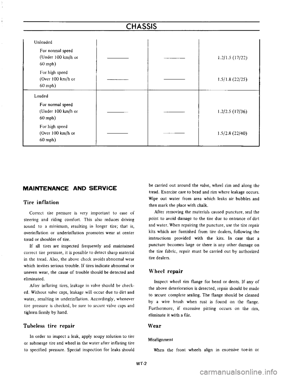
Unloaded
For
normal
speed
U
nder
100
km
h
or
60
mph
F
or
high
speed
Over
100
km
h
or
60
mph
Loaded
For
normal
speed
Under
100
kmlh
or
60
mph
For
high
speed
Over
100
kmlh
or
60
mph
MAINTENANCE
AND
SERVICE
Tire
inflation
Correct
tire
pressure
is
very
importan
t
to
ease
of
steering
and
riding
comfort
This
also
reduces
driving
sound
to
a
minimum
resulting
in
longer
tire
that
is
overinfla
lion
or
underinflation
promotes
wear
at
center
tread
or
shoulder
of
tire
If
all
tires
are
inspected
frequently
and
maintained
correct
tire
pressure
it
is
possible
to
detect
sharp
material
in
the
tread
Also
the
above
check
avoids
abnormal
wear
which
invites
serious
trouble
If
tires
indicate
abnormal
or
uneven
wear
the
cause
of
trouble
should
be
detected
and
eliminated
After
inflating
tices
leakage
in
valve
should
be
check
cd
Without
valve
caps
leakage
will
occur
due
to
dirt
and
water
resulting
in
underinOation
Accordingly
whenever
tire
pressure
is
checked
be
sure
to
secure
valve
caps
and
tighten
firmly
by
hand
Tubeless
tire
repair
In
urder
to
inspect
a
leak
apply
soapy
solution
to
tire
or
submerge
tire
and
wheel
in
the
water
after
inflating
tire
to
specified
pressure
Special
inspection
for
leaks
should
12
15
17
22
1
5
1
8
22
25
1
2
2
5
I
7
36
1
5
2
8
22
40
be
carried
out
around
the
valve
wheel
rim
and
along
the
tread
Exercise
care
to
bead
and
rim
where
leakage
occurs
Wipe
out
water
from
area
which
leaks
air
bubbles
and
then
mark
the
place
with
chalk
After
remuving
the
materials
caused
puncture
seal
the
point
to
avoid
damage
to
the
tire
due
to
entrance
of
dirt
and
water
When
repairing
the
puncture
use
the
tire
repair
kits
which
are
furnished
from
tire
dealers
following
the
instructions
provided
with
the
kits
In
case
that
a
puncture
becomes
large
or
there
is
any
other
damage
on
the
tire
fabric
repair
must
be
carried
out
by
authorized
tire
dealers
Wheel
repair
Inspect
wheel
rim
flange
for
bend
or
dents
If
any
of
the
above
deterioration
is
detected
repair
should
be
made
to
secure
complete
sealing
The
flange
should
be
cleaned
by
a
wire
brush
when
rust
is
found
on
the
flange
Furthermore
if
excessive
pitting
occurs
on
the
rim
eliminate
it
with
a
file
Wear
Misalignment
When
the
front
wheels
align
in
excessive
toe
in
or
WT
2
Page 290 of 513
III
r
AJ
r
oll
t
1
J
1
J
ti
i
1
tl
FOREWORD
This
scrviee
manual
has
been
prepared
lor
the
purpose
of
assistinf
service
persunnel
of
authorized
NISSAN
DA
TSUN
dealers
in
providing
effective
service
and
maintenance
of
the
1973
Datsun
1200
I
il
Since
proper
maintenance
and
serVIce
are
absolutely
essential
in
satisfying
the
owners
of
DatSlLn
this
manual
should
be
kept
in
a
handy
place
for
ready
reference
and
should
be
mrefully
studied
This
nUl
wal
indudes
procedures
for
maintenance
adjustments
mmor
service
operations
renwval
and
installation
IInd
for
disassembly
and
assembly
of
ram
ponents
The
Quick
Reference
lndex
on
the
first
page
enable
the
user
to
quickly
locate
and
desired
tion
4t
the
beginning
of
each
individual
section
is
a
table
of
contents
which
gives
the
page
number
on
which
each
major
subject
begins
An
index
is
placed
at
the
beginning
of
each
major
subject
withill
the
sectioll
The
Special
Tools
when
required
presented
at
the
Sf
section
411
information
illustrations
and
specificatiolls
contained
in
this
manual
are
based
Oll
the
latest
product
inJormation
available
at
the
time
of
publication
approval
Rights
for
tIltl
rnali
11
of
specificatiuns
llnd
mpthods
at
lilY
time
are
reserved
I
I
I
I
NISSAN
MOTOR
CO
TOKYO
APAN
LTD
f
t
I
I
t
J
1972
NlSSAN
MOTOR
CO
LTD
i
t
r
f
i
o
c
1
I
I
l
1
10
I
It
r
f
K
I
1
I
i
I
r
I
i
i
t
j
I
r
7
T
l
1
r
i
i
t
Llo
tff
t
I
1
O
I
trr
rd
I
At
4
rei
1
0
Ii
0
cll
I
f
I
J
i
J
iF
U
y
tn
1
I
I
I
I
i
t
If
tij
1
li
I
J
H
a
r
1
i
I
V
j
lio
4
l
j
i
y
o
J
A
co
L
i
I
I
I
Jil
iLl4
j
l
t1
J
1
i
t
Page 295 of 513
r
FOREWORD
This
service
manual
has
been
prepared
for
the
pnrpose
uf
assisling
service
personnel
of
llllthurized
NISSAN
DATSUN
dealers
in
pruviding
e
feetive
service
and
maintenance
uf
the
973
Datsun
2VV
inee
proper
maintenance
and
scroice
arc
absolutely
essential
ill
satisfying
the
uwners
of
Datsun
Ihis
manual
should
be
kepi
in
a
handy
place
fur
ready
reference
and
shollld
be
carefully
studied
This
manual
indudes
procedures
fnr
maintenance
adjlU
tments
mInor
serVice
ofJf
raliun
mmoval
and
inslallation
and
for
disassl
mbly
and
asscmlJl
of
com
ponents
TIle
Ouick
Reji
ence
Index
on
the
jirst
page
enable
the
user
to
quickly
locale
and
de
ired
sed
ion
AI
Ihe
beginning
of
each
individual
see
ion
is
a
lable
of
contents
which
gives
the
page
number
on
which
each
majur
subject
begins
4n
index
is
placed
at
Ihe
beginning
of
each
majur
subject
within
the
section
1
1
Special
Tools
when
required
presented
at
the
SF
sedion
4ll
informatiun
illustrations
arid
specifications
cOlliaifwd
in
this
manual
are
Jw
ed
on
the
latest
product
infurmation
available
at
Ihe
time
of
publication
appruval
Rights
fur
alternatiun
of
specifications
and
methods
at
uny
time
are
reserved
NISSAN
MOTOR
CO
TOKYO
JAPAN
LTD
@
1972
NISSAN
IOTOR
co
LTD
Page 416 of 513

FUEl
SYSTEM
EVAPORATIVE
EMISSION
CONTROL
SYSTEM
CONTENTS
OESCRI
PTION
Flow
guide
valve
MAINTENANCE
AND
TESTING
Checking
fuel
tank
vapor
liquid
separator
and
vapor
vent
I
ins
EF
25
EF
26
EF
26
EF
26
DESCRIPTION
This
system
consists
of
four
basic
elements
indicated
below
I
Fuel
tank
with
positive
sealing
filler
cap
with
relief
valve
2
Vapor
liquid
separator
3
Vapor
vent
line
4
Flow
guide
valve
The
flow
guide
valve
prevents
blow
by
gas
from
flowing
into
the
fuel
tank
and
guides
fresh
air
into
it
preventing
gasoline
vapor
from
escaping
into
the
carbure
tor
air
cleaner
Fl
me
ester
I
f
Flow
Thev
lve
opens
when
thlp
1l
rO
Inch
Hg
O
Positive
unk
venlI1atlon
PCV
hoe
Checking
fuel
tank
vacuum
relief
valve
operation
Checking
flow
guide
valve
EF
27
EF
27
Flow
guide
valve
operates
and
blow
by
gas
and
gasoline
vapor
flow
as
follows
When
the
engine
is
not
running
the
vapor
vent
line
vapor
liquid
separator
and
fuel
tank
are
filled
with
gasoline
vapor
produced
in
the
sealed
type
fuel
tank
A
flow
guide
valve
opens
when
the
gas
pressure
is
above
IOromHg
0
4
in
Hg
The
gas
passed
through
the
flow
guide
valve
2
is
accumulated
in
the
crankcase
Once
the
engine
starts
evaporates
in
the
crankcase
manifold
and
carburetor
air
cleaner
is
sucked
into
the
manifold
for
combustion
When
the
pressure
of
the
sealed
type
fuel
tank
vapor
liquid
separator
and
vapor
vent
line
becomes
negative
by
decreasing
the
fuel
the
flow
guide
valve
I
opens
to
send
fresh
air
from
the
carburetor
air
cleaner
to
the
fuel
tank
lill
K
riquidllepilrflOr
T
VilPOl
vent
line
Positiveteilling
lillercap
Fig
EF
37
Evaporative
emission
control
system
EF
25
Page 417 of 513
ENGINE
ffi68
mmAq
14
5
mAq
3
way
connector
Cock
II
M
nam
e
Flow
guide
valve
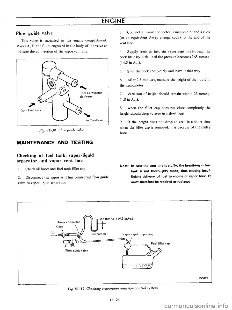
This
valve
is
mounted
in
the
engine
compartment
f
tHks
A
F
and
C
are
engraved
in
the
body
of
the
valve
to
indicate
the
connection
of
the
vapor
vent
line
l
l
1
from
Fuel
tank
to
Crankcase
Fig
EF
3B
Flow
guide
valve
MAINTENANCE
AND
TESTING
Checking
of
fuel
tank
vapor
liquid
separator
and
vapor
vent
line
Check
all
hoses
and
fuel
tank
filler
cap
2
Disconnect
the
vapor
vent
line
connecting
flow
guide
valve
to
vapor
liquid
separator
Flow
guide
valve
3
Connect
a
J
way
connector
a
manometer
and
a
l
ul
k
or
an
equivalent
3
wav
change
cock
to
the
end
of
the
vent
line
4
Supply
fresh
air
into
the
vapor
vent
line
through
the
cock
little
by
little
until
the
pressure
becomes
368
romAq
14
5
in
Aq
5
Shut
the
cock
completely
and
leave
it
that
way
6
After
2
5
minutes
measure
the
height
uf
the
liquid
in
the
manometer
7
Variation
of
height
should
remain
within
25
mmAq
1
0
in
Aq
8
When
the
filler
cap
does
not
close
completely
the
height
should
drop
to
zero
in
a
short
time
9
I
f
the
height
docs
not
drop
to
zero
in
a
short
time
when
the
filler
cap
is
removed
it
is
because
of
the
stuffy
hose
Note
In
case
the
vent
line
is
stuffy
the
breathing
in
fuel
tank
is
not
thoroughly
made
thus
causing
insuf
ficient
delivery
of
fuel
to
engine
or
vapor
lock
It
must
therefore
be
repaired
or
replaced
1
m
eparator
1
Fuel
filler
cap
Y
XI
EC029
Fig
EF
39
Checking
evaporative
emission
control
system
EF
26
Page 506 of 513
TRANSMISSION
f
fli
1
1
J
THREE
SPEED
TRANSMISSION
It
l
I
1
n
I
l
p
I
1P4
e
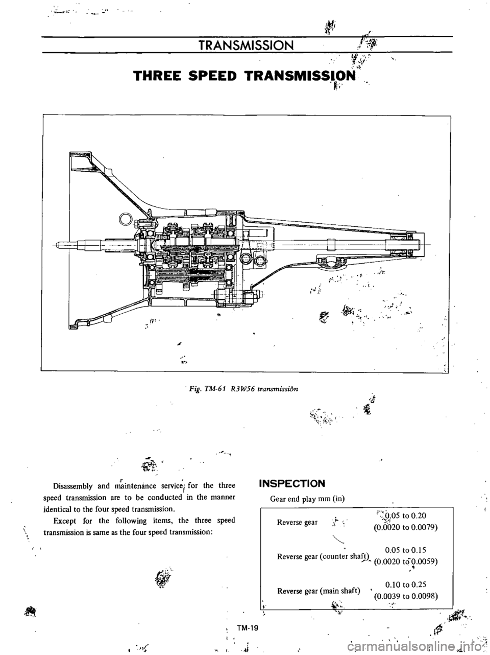
Fig
TM
61
R3W56
transmissiOn
J
l
l
T
Disassembly
and
maintenance
service
for
the
three
speed
transmission
are
to
be
conducted
in
the
manner
identical
to
the
four
speed
transmission
Except
for
the
following
items
the
three
speed
transmission
is
same
as
the
four
speed
transmission
INSPECTION
Gear
end
play
mm
in
Reverse
gear
0
05
to
0
20
0
0
020
to
0
0079
0
05
to
0
IS
Reverse
gear
counter
sha
n
0
0020
to
0
0059
I
I
Reverse
gear
main
shaft
l
0
10
to
0
25
0
0039
to
0
0098
TM
19
4iI1
1
J