Page 333 of 513

ENGINE
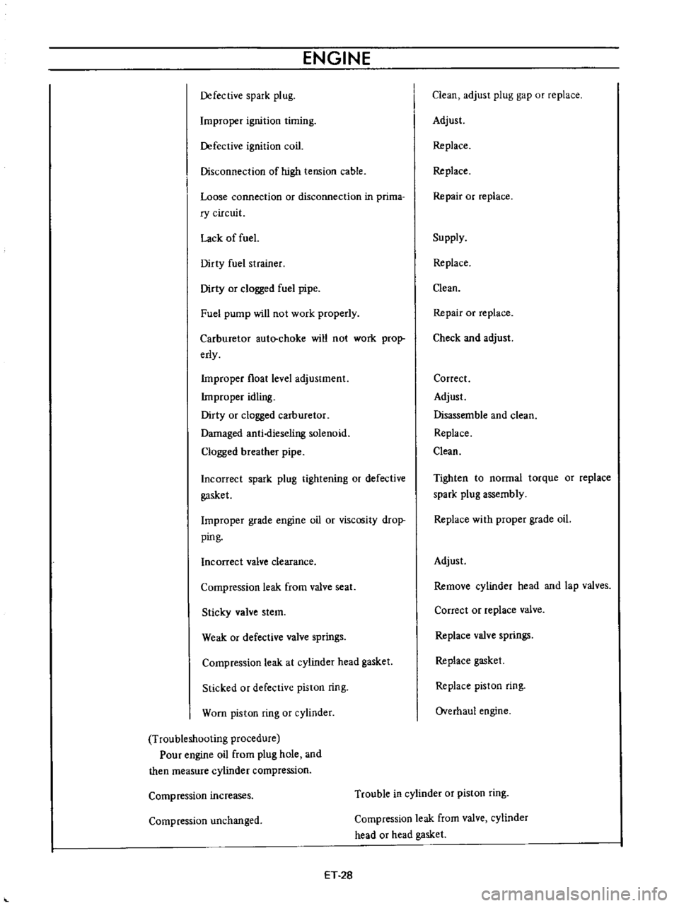
Defective
spark
plug
Improper
ignition
timing
Defective
ignition
coil
Disconnection
of
high
tension
cable
Loose
connection
or
disconnection
in
prima
ry
circuit
Lack
of
fuel
Dirty
fuel
strainer
Dirty
or
clogged
fuel
pipe
Fuel
pump
will
not
work
properly
Carburetor
auto
choke
will
not
work
prop
erly
Improper
float
level
adjustment
Improper
idling
Dirty
or
clogged
carburetor
Damaged
anti
dieseling
solenoid
Clogged
breather
pipe
Incorrect
spark
plug
tightening
or
defective
gasket
Improper
grade
engine
oil
or
viscosity
drop
ping
Incorrect
valve
clearance
Compression
leak
from
valve
seat
Sticky
valve
stem
Weak
or
defective
valve
springs
Compression
leak
at
cylinder
head
gasket
Sticked
or
defective
piston
ring
Worn
piston
ring
or
cylinder
Troubleshooting
procedure
Pour
engine
oil
from
plug
hole
and
then
measure
cylinder
compression
Clean
adjust
plug
gap
or
replace
Adjust
Replace
Replace
Repair
or
replace
Supply
Replace
Clean
Repair
or
replace
Check
and
adjust
Correct
Adjust
Disassemble
and
clean
Replace
Clean
Tighten
to
normal
torque
or
replace
spark
plug
assembly
Replace
with
proper
grade
oil
Adjust
Remove
cylinder
head
and
lap
valves
Correct
or
replace
valve
Replace
valve
springs
Replace
gasket
Replace
piston
ring
Overhaul
engine
Compression
increases
Trouble
in
cylinder
or
piston
ring
Compression
unchanged
Compression
leak
from
valve
cylinder
head
or
head
gasket
ET
28
Page 335 of 513

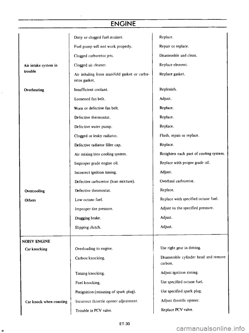
Air
intake
system
in
trouble
Overheating
Overcooling
Others
NOISY
ENGINE
Car
knocking
Car
knock
when
coasting
ENGINE
Diny
ur
clogged
fuel
strainer
Fuel
pump
will
not
work
properly
Clogged
carburetor
jets
Clogged
air
cleaner
Air
inhaling
from
manifold
gasket
or
carbu
retor
gasket
Insufficient
coolant
Loosened
fan
belt
Worn
or
defective
fan
belt
Defective
thermostat
Defective
water
pump
Clogged
or
leaky
radiator
Defective
radiator
filler
cap
Air
mixing
into
cooling
system
Improper
grade
engine
oil
Incorrect
ignition
timing
Defective
carburetor
lean
mixture
Defective
thermostat
Low
octane
fuel
Improper
tire
pressure
Dragging
brake
Slipping
clutch
Overloading
to
engine
Carbon
knocking
Timing
knocking
Fuel
knocking
Preignition
misusing
of
spark
plug
Incorrect
throttle
opener
adjustment
Trouble
in
PCV
valve
ET
30
Replace
Repair
or
replace
Disassemble
and
clean
Replace
element
Replace
gasket
Replenish
Adjust
Replace
Replace
Replace
Flush
repair
or
replace
Replace
Retighten
each
part
of
cooling
system
Replace
with
proper
grade
oil
Adjust
Overhaul
carburetor
Replace
Replace
with
specified
octane
fuel
Adjust
to
the
specified
pressure
Adjust
Adjust
Use
right
gear
in
driving
Disassemble
cylinder
head
and
remove
carbon
Adjust
ignition
timing
Use
specified
octane
fuel
Use
specified
spark
plug
Adjust
throttle
opener
Replace
PCV
valve
Page 338 of 513

EMISSION
CONTROL
AND
TUNE
UP
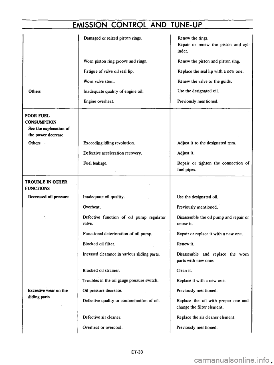
Othm
POOR
FUEL
CONSUMPTION
See
the
explanation
of
the
power
decrease
Othe
TROUBLE
IN
OTHER
FUNCfIONS
Decreased
oil
pressure
Excessive
wear
on
the
sliding
parts
Damaged
or
seized
piston
rings
Worn
piston
ring
groove
and
rings
Fatigue
ofvalve
oil
seal
lip
Worn
valve
stem
Inadequate
quality
of
engine
oiL
Engine
overheat
Exceeding
idling
revolution
Defective
acceleration
recovery
Fuel
leakage
Inadequa
Ie
oil
quality
Overheat
Defective
function
of
oil
pump
regulator
valve
Functional
deterioration
of
oil
pump
Blocked
oil
ftIter
nerased
clearance
in
various
sliding
parts
Blocked
oil
strainer
Troubles
in
the
oil
gauge
pressure
switch
Oil
pressure
decrease
Defective
quality
or
contamination
of
oil
Defective
air
cleaner
Overheat
or
overcoal
ET
33
Renew
the
rings
Repair
or
renew
the
piston
and
cyl
inder
Renew
the
piston
and
piston
ring
Replace
the
seal
lip
with
a
new
one
Renew
the
valve
or
the
guide
Use
the
designated
oiL
Previously
mentioned
Adjust
it
to
the
designated
rpm
Adjust
it
Repair
or
tighten
the
connection
of
fuel
pipes
Use
the
designated
oil
Previously
mentioned
Disassemble
the
oil
pump
and
repair
or
renew
it
Repair
or
replace
it
with
a
new
one
Renew
it
Disassemble
and
replace
the
worn
parts
with
new
ones
Clean
it
Replace
it
with
a
new
one
Previously
mentioned
Replace
the
oil
with
proper
one
and
change
the
ftIter
elemerit
Replace
the
air
cleaner
element
Previously
mentioned
Page 346 of 513
ENGINE
l
JJ
l
Ii
Fig
EM
t7
Water
pump
r
1
13
Remove
the
fuel
pump
14
Remove
the
rocker
shaft
assembly
and
push
rods
Fig
EM
18
Rocker
shaft
assembly
removal
IS
Remove
the
cylinder
head
assembly
Fig
EM
19
Cylinder
head
bolts
removal
sequence
16
Invert
the
engine
17
Remove
the
oil
pan
and
oil
strainer
Fig
EM
20
Oil
stromer
removal
18
Remove
the
timing
chain
cover
and
the
chain
tensioner
19
Remove
the
crankshaft
and
camshaft
sprockets
together
with
the
timing
chain
Fig
EM
21
Timing
chain
cover
removal
20
Rotate
the
engine
a
quarter
turn
and
remove
the
piston
and
connecting
rod
assembly
Take
off
the
con
necting
rod
bearings
at
the
same
time
and
keep
them
in
order
EM
6
Page 372 of 513
ENGINE
27
Install
the
oil
pump
with
oil
filter
28
Install
the
alternator
fan
and
fan
belt
29
Install
the
fuel
pump
30
Install
the
distributor
assembly
Fig
EM
B7
Timing
maTk
Fig
EM
SS
Distributor
installation
EM
32
Notes
3
Set
the
No
1
piston
to
its
top
dead
center
of
the
compression
stroke
b
Before
installation
return
the
distributor
rotor
approximately
60
degrees
from
its
regular
posi
tion
Insert
the
assembly
meshing
the
distributor
drive
gear
and
driven
gear
After
installation
the
distributor
rotor
should
come
into
contact
with
the
mark
on
the
rotor
cap
fitting
as
shown
in
the
Figure
31
Install
the
spark
plugs
and
connect
the
distributor
to
plug
high
tension
lead
wire
32
Install
the
fuel
hoses
and
tubes
33
Install
the
clutch
cover
assembly
34
Install
the
engine
stingers
and
crankcase
ventilation
hose
35
Dismount
the
engine
from
the
working
stand
Install
the
engine
mountings
Page 379 of 513

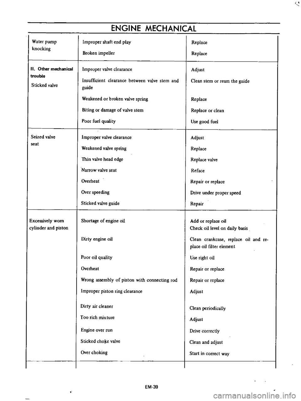
Water
pump
knocking
II
Other
mechanical
trouble
Sticked
valve
Seized
valve
seat
Excessively
worn
cylinder
and
piston
ENGINE
MECHANICAL
Improper
shaft
end
play
Broken
impeller
Improper
valve
clearance
Insufficient
clearance
between
valve
stem
and
guide
Weakened
or
broken
valve
spring
Biting
or
damage
ofvalve
stem
Poor
fuel
quality
Improper
valve
clearance
Weakened
valve
spring
Thin
valve
head
edge
Narrow
valve
seat
Overheat
Over
speeding
Sticked
valve
guide
Shortage
of
engine
oil
Dirty
engine
oil
Poor
oil
quality
Overheat
Wrong
assembly
of
piston
with
connecting
rod
Improper
piston
ring
clearance
Dirty
air
cleaner
Too
rich
mixture
Engine
over
run
Slicked
cho
e
valve
Over
choking
EM
39
Replace
Replace
Adjust
Clean
stem
or
ream
the
guide
Replace
Replace
or
clean
Use
good
fuel
Adjust
Replace
Replace
valve
Reface
Repair
or
replace
Drive
under
proper
speed
Repair
Add
or
replace
oil
Check
oil
level
on
daily
basis
Clean
crankcase
replace
oil
and
re
place
oil
fIlter
element
use
right
oil
Repair
or
replace
Repair
or
replace
Adjust
Clean
periodically
Adjust
Drive
correctly
Clean
and
adjust
Start
in
correct
way
Page 391 of 513
DATSUN
1200
MODEL
8110
SERIES
I
NISSAN
I
NI55AN
MOTOR
CO
LTD
TOKYO
JAPAN
SECTION
EF
FUEL
SYSTEM
AUTOMATIC
TEMPERATURE
CONTROL
AIR
CLEANER
A
T
C
AIR
CLEANER
FUEL
S
iRAINER
FUEL
PUMP
CARBURETOR
EVAPORATIVE
EMISSION
CONTROL
SYSTEM
HI
H
5
H
5
H
B
EF
25
Page 396 of 513

FUEl
SYSTEM
FUEL
STRAINER
DESCRIPTION
The
fuel
strainer
is
of
a
cartridge
type
It
uses
paper
element
as
strainer
element
which
can
be
checked
for
condition
from
outside
This
strainer
cannot
be
cleaned
Replace
the
strainer
at
the
specified
service
interval
or
if
it
becomes
clogged
or
restricted
REMOVAL
Disconnect
inlet
and
outlet
fuel
lines
from
fuel
strainer
and
remove
fuel
strainer
Note
Before
disconnecting
fuel
lines
use
a
container
to
receive
the
remaining
fuel
in
lines
r
@
I
I
Il
QY
I
I
I
elementl
3
Cover
@
EF005
Fig
EF
10
Sectional
view
of
caTtridge
type
fuel
stTaineT
FUEL
PUMP
CONTENTS
DESCRIPTION
FUEL
PUMP
TESTING
Static
pressure
test
Capacity
test
EF
5
EF
6
EF
6
EF
6
DESCRIPTION
The
fuel
pump
transfers
gasoline
from
the
tank
to
the
carburetor
in
sufficient
quantity
to
meet
engine
require
ments
at
any
speed
or
load
The
fuel
pump
is
of
the
diaphragm
type
REMOVAL
AND
DISASSEMBLY
INSPECTION
ASSEMBLY
EF
7
EF
B
EF
B
The
fuel
pump
consists
of
a
body
rocker
arm
and
link
assembly
fuel
diaphragm
fuel
diaphragm
spring
seal
inlet
and
outlet
valves
The
fuel
diaphragm
consists
of
specially
treated
rubber
which
is
not
affected
by
gasoline
held
together
with
two
metal
discs
and
a
pull
rod
EF
5