1973 DATSUN B110 oil temperature
[x] Cancel search: oil temperaturePage 53 of 513

AUTOMATIC
TRANSMISSIO
N
TROUBLE
DIAGNOSES
AND
ADJUSTMENT
INSPECTION
AND
ADJUSTMENT
BEFORE
TROUBLE
DIAGNOSIS
Testing
instrument
for
inspection
Checking
oil
level
Inspection
and
repair
of
oil
leakage
Checking
engine
idling
rpm
Checking
and
adjusting
kick
down
switch
and
downshift
solenoid
Inspection
and
adjustment
of
manual
linkage
Checking
and
adjusting
inhibitor
switch
STALL
TEST
Stall
test
procedures
Judgement
As
the
troubles
on
the
automatic
transmission
can
be
mostly
repaired
by
doing
simple
adjustment
so
do
not
disassemble
immediately
if
the
auto
m
tic
transmission
is
in
trouble
Firstly
inspect
and
adjust
the
auto
matic
transmission
with
mounting
on
vehicle
by
observing
the
trouble
shooting
chart
If
the
trouble
could
not
be
solved
by
this
procedure
then
remove
and
disassemble
the
automatic
transmis
sion
It
is
advisable
to
check
overhaul
and
repair
each
point
in
the
order
itemized
in
the
trouble
shooting
chart
l
In
the
trouble
shooting
chart
the
diagnosis
items
are
arranged
in
the
order
from
easy
to
difficult
and
there
fore
please
follow
these
items
The
transmission
should
not
be
removed
unless
necessary
2
The
test
and
adjustment
for
trou
ble
diagnosis
should
be
made
on
the
basis
of
standard
values
and
the
data
should
be
recorded
ROAD
TEST
Car
speed
at
gear
shift
Checking
speed
changing
condition
Checking
items
during
speed
change
Shift
schedule
LINE
PRESSURE
TEST
Line
pressure
governor
feed
pressure
Judgement
in
measuring
line
pressure
TROUBLE
SHOOTING
CHART
Inspecting
items
Trouble
shooting
chart
for
3N71
B
Automatic
Transmission
Trouble
shooting
guide
for
3N718
Automatic
Transmission
CONTENTS
AT
49
AT
49
AT
49
AT
50
AT
50
AT
50
AT
51
AT
51
AT
51
AT51
AT
52
INSPECTION
AND
AD
JUSTMENT
BEFORE
TROUBLE
DIAGNOSIS
Testing
instrument
for
inspection
1
Engine
tachometer
2
Vacuum
gauge
3
Oil
pressure
gauge
It
is
convenient
to
install
these
instruments
in
a
way
that
allows
meas
urements
to
be
made
from
the
driver
s
seat
Checking
oil
level
In
checking
the
automatic
transmis
sion
the
oil
level
and
the
condition
of
oil
around
the
oil
level
gauge
should
be
examined
every
5
000
km
3
000
miles
These
steps
are
easy
and
effec
live
in
trouble
shooting
as
some
change
of
oil
conditions
are
linked
with
developed
troubles
in
many
cases
AT
49
AT
52
AT
52
AT
53
AT
53
AT
53
AT
53
AT
53
AT
54
AT
54
AT
54
AT
55
AT
5B
For
instance
Lack
of
oil
causes
defective
opera
tion
by
making
the
clutches
and
brakes
slip
developing
severe
wear
The
cause
of
this
operation
is
that
the
oil
pump
has
begun
to
suck
air
which
caused
oil
foaming
thus
rapidly
deteriora
ting
the
oil
quality
and
pro
ducing
sludge
and
varnish
Meanwhile
excessive
oil
is
also
bad
as
in
the
case
of
a
lack
of
oil
because
of
oil
foaming
by
being
stirred
up
by
the
gears
Moreover
in
high
speed
driving
with
excessive
oil
in
the
trans
mission
the
oil
often
blows
out
from
the
breather
I
Measuring
oil
level
When
checking
the
fluid
level
start
the
engine
and
run
it
until
normal
operating
temperatures
oil
tempera
ture
50
to
800e
122
to
176
F
Approximately
ten
minute
operation
will
elevate
the
temperature
to
this
range
and
enigne
idling
conditions
are
stabilized
Then
apply
the
brakes
and
move
the
transmission
shift
lever
Page 54 of 513

through
all
drive
positions
and
place
the
lever
in
park
P
position
In
this
inspection
the
car
must
be
placed
on
a
level
surface
The
amount
of
the
oil
varies
with
the
temperature
As
a
rule
the
oil
level
must
be
measured
after
its
tempera
ture
becomes
sufficiently
high
I
Fill
the
oil
to
the
line
H
The
difference
of
capacities
between
both
H
and
L
is
approximately
0
4
liter
7
8
U
S
pt
3
4
Imper
pt
and
therefore
take
care
not
to
fill
beyond
the
line
H
2
At
the
time
of
the
above
topping
up
and
changing
of
oil
care
should
be
taken
of
to
prevent
mixing
the
oil
with
dust
and
water
2
Inspecting
oil
condition
The
condition
of
oil
sticking
to
the
level
gauge
indicates
whether
to
over
haul
and
repair
the
transmission
or
look
for
the
defective
part
If
the
oil
has
deteriorated
into
a
varnish
like
quality
it
causes
the
con
trol
valve
to
stick
The
blackened
oil
gives
the
proof
of
the
burned
clutch
brake
band
etc
In
these
cases
the
transmission
must
be
replaced
Notes
a
In
oil
level
checking
use
special
paper
waste
to
handle
the
level
gauge
and
take
care
not
to
let
the
scraps
of
paper
and
cloth
tick
to
the
gauge
b
Insert
the
gauge
fully
and
take
it
out
quickly
before
splashing
oil
adheres
to
the
gauge
and
theu
observe
the
level
c
Use
automatic
transmission
fluid
having
DEXRON
iden
tIficatIon
only
in
the
3N71
B
automatic
transmission
d
Pay
atteutIon
because
the
oil
to
be
used
dIffers
from
that
i
used
in
the
Nissan
Full
Automatic
Transmission
3N7IA
Never
mix
the
oil
with
that
CHASSIS
Inspection
and
repair
of
oil
leakage
When
oil
leakage
takes
place
the
portion
near
the
leakage
is
covered
with
oil
presenting
difficulty
in
de
tecting
the
spot
Therefore
the
places
where
oil
seals
and
gaskets
are
equipped
are
enumerated
below
I
Converter
housing
The
rubber
ring
of
oil
pump
hous
ing
The
oil
eaI
of
oil
pump
housing
The
oil
seal
of
engine
crankshaft
The
bolts
of
converter
housing
to
case
2
Transmission
and
rear
extension
Junction
of
transmission
and
rear
extension
Oil
tube
connectors
Oil
pan
Oil
pressure
inspection
holes
Refer
to
Figure
AT
112
The
mounting
portion
of
vacuum
diaphragm
and
downshift
solenoid
Breather
and
oil
charging
pipe
Speedometer
pinion
sleeve
The
oil
seal
of
rear
extension
To
exactly
locate
the
place
of
oil
leakage
proceeds
as
follows
Place
the
vehicle
in
a
pit
and
by
sampling
the
leaked
oil
examine
whe
ther
it
is
the
torq
le
converter
oil
or
not
The
torque
converter
oil
assumes
color
like
red
wine
when
shipped
from
the
factory
so
it
is
ea
ily
distin
guished
from
engine
oil
or
gear
oil
Cleanly
wipe
off
the
leaking
oil
and
dust
and
detect
the
spot
of
oil
leakage
Use
nonflammable
organic
solvent
such
as
carbon
tetrachloride
for
wip
ing
Raise
the
oil
temperature
by
op
erating
the
engine
and
shift
the
lever
to
0
to
heighten
the
oil
pressure
The
spot
of
oil
leakage
will
then
be
found
more
easily
Note
A
the
oil
leakage
from
the
breather
does
not
take
place
except
when
running
at
high
speed
it
is
impossible
to
locate
the
spot
of
leakage
with
vehicle
stalled
AT
50
Checking
engine
idling
rprn
The
engine
idling
revolution
should
be
properly
adjusted
If
the
engine
revolution
is
too
low
the
engine
does
not
operate
smoothly
and
if
too
high
a
strong
shock
or
creep
develops
when
changing
over
from
N
to
D
or
R
Specified
idling
speed
650
rpm
at
D
position
800
rpm
at
N
position
Checking
and
adjusting
kick
down
switch
and
downshift
solenoid
When
the
kick
down
operation
is
not
made
properly
or
the
speed
chang
ing
point
is
too
high
check
the
kick
down
switch
downshift
solenoid
and
wiring
between
them
When
the
igni
tion
key
is
positioned
at
the
1st
stage
and
the
accelerator
pedal
is
depressed
deeply
the
switch
contact
should
be
closed
and
the
solenoid
should
click
If
it
does
not
click
it
indicates
a
defect
Then
check
each
part
with
the
testing
instruments
See
Figure
AT
I09
0
0
1
M
r
7
I
Y
ATl08
Fig
A
T
l
09
Downshift
solenoid
Note
Watch
for
oil
leakage
from
transmission
case
Page 55 of 513

c
Inspection
and
adJu
Stmenf
trouble
first
check
the
linhge
f
no
1
i
jI
fect
is
found
in
the
lin1
age
check
of
manu
a
l
liiiJ
i
the
inhibitor
switch
Th
d
1F
aI
S
t
th
I
I
f
e
a
JU
i
J
u
epara
e
e
range
se
eet
ever
rom
Iy
important
ii
s3
ns
etion
of
oil
the
lower
shift
rod
and
turn
the
range
1
level
for
the
automatiC
tran
smission
select
lever
to
N
Therefore
great
care
should
be
exer
Note
In
the
position
N
the
slot
of
cised
because
defective
adjustment
will
the
manual
shaft
is
vertical
result
in
the
breakdown
of
the
trans
By
the
use
of
the
tester
check
the
two
bIack
yellow
BY
wires
from
the
inhibitor
switch
in
the
ranges
N
and
P
and
the
two
red
bIack
RB
wires
in
the
range
R
for
continuity
Turn
range
select
lever
to
both
directions
from
each
lever
set
position
and
check
each
continuity
range
It
is
normal
if
the
electricity
is
on
while
the
lever
is
within
an
angle
of
about
3
0
on
both
sides
from
each
lever
set
line
How
ever
if
its
continuity
range
is
obvi
ously
unequal
on
both
sides
the
adjustment
is
required
f
any
malfunction
is
found
un
screw
the
fastening
nut
of
the
range
selector
lever
and
two
fastening
bolts
of
the
switch
body
and
then
remove
the
machine
screw
under
the
switch
body
Adjust
the
manual
shaft
correct
ly
to
the
position
N
by
means
of
the
selector
lever
When
the
slot
of
the
shaft
becomes
vertical
the
detent
works
to
position
the
shaft
correctly
with
a
click
sound
Move
the
switch
slightly
aside
so
that
the
screw
hole
will
be
aligned
with
the
pin
hole
of
the
internal
rotor
combined
with
the
manual
shaft
and
check
their
alignment
by
inserting
a
1
5
0101
0
0591
in
diameter
pin
into
the
holes
If
the
alignment
is
made
correct
1
5ten
the
switch
body
with
the
bolts
pull
out
the
pin
and
tighten
up
the
screw
again
into
the
hole
and
fasten
the
selector
lever
as
before
Check
over
again
the
continuity
with
the
tester
If
the
malfunction
still
remains
replace
the
inhibitor
switch
mission
Inspection
Pull
the
selector
lever
toward
you
and
turn
it
so
far
as
p
to
1
range
where
clicks
will
be
felt
by
hand
This
is
the
detent
of
manual
valve
in
the
body
and
indicates
the
correct
posi
tion
of
the
lever
Inspect
whether
the
pointer
of
selector
dial
corresponds
to
this
point
and
also
whether
the
lever
comes
in
alignment
with
the
stepping
of
posi
tion
plate
when
it
is
released
Adjustment
This
procedure
can
be
accom
plished
by
referring
to
Removal
and
nstallation
Checking
and
adjusting
inhibitor
switch
The
inhibitor
switch
serves
to
light
the
reverse
lamp
in
the
range
R
of
the
transmission
operation
and
also
to
rotate
the
starter
motor
in
the
ranges
N
and
P
j
r@
I
If
r
f
B
@
I
Jt
@
@
c
v@
i
r
fji
AT109
1
Inhibitor
switch
2
Manual
shaft
3
Washer
4
Nut
5
Manual
plate
Fig
AT
II
0
Con
truction
of
inhibitor
witch
6
Washer
7
Nut
8
Inhibitor
switch
9
Range
select
lever
Check
whether
the
reverse
lamp
and
the
starter
motor
operate
normal
ly
in
these
ranges
If
there
is
any
t
ki
A
mm
ATIC
TRANSMISSION
STALL
TEST
The
purpose
of
this
test
is
to
check
the
transmission
and
engine
for
trou
ble
by
measuring
the
maximwn
num
bers
of
revolutions
of
the
engine
while
vehicle
is
held
in
a
stalled
condition
and
the
carburetor
is
in
full
throttle
operation
with
the
selector
lever
in
AT
51
rang
s
D
2
and
I
respectively
and
by
com
pairing
the
measured
re
sults
with
the
standard
values
Standard
stall
revolution
1
750
to
2
000
rpm
Components
to
be
tested
and
test
items
1
Clutches
brake
and
band
in
trans
mission
for
slipping
2
Torque
converter
for
function
3
Engine
for
overall
property
Stall
test
procedures
Before
testing
check
the
enigne
oil
and
torque
converter
oil
warm
up
the
engine
cooling
water
to
the
suitable
temperature
by
warming
up
ope
ration
at
1
200
rpm
with
the
selector
lever
in
the
range
P
for
several
minutes
and
warm
up
the
torque
converter
oil
to
the
suitable
temperature
60
to
IOOoC
140
to
2120F
1
Mount
the
engine
tachometer
at
a
location
that
allows
good
visibility
from
the
driver
s
seat
and
put
a
mark
on
specified
revolutions
on
the
meter
2
Secure
the
front
and
rear
wheels
completely
with
chocks
and
apply
the
hand
brake
Be
sure
to
depress
the
brake
pedal
firmly
with
the
left
foot
before
depressing
down
the
accelerator
pedal
3
Throw
the
selector
lever
into
the
range
D
4
Slowly
depress
the
accelerator
pedal
down
till
the
throttle
valve
is
fully
opened
Quickly
read
and
record
the
engine
revolution
when
the
engine
begins
to
rotate
steadily
and
then
release
the
accelerator
pedal
5
Turn
the
selector
lever
into
N
and
operate
the
enigne
at
approxi
mately
1
200
rpm
for
more
than
one
minute
to
cool
down
the
torque
con
verter
oil
and
coolant
6
Make
similar
stall
tests
in
the
ranges
2
I
and
R
Note
The
stall
test
operation
as
spec
ified
in
the
item
4
should
be
made
within
five
seconds
If
it
takes
too
long
the
oil
deterio
rates
and
the
clutches
brake
Page 62 of 513

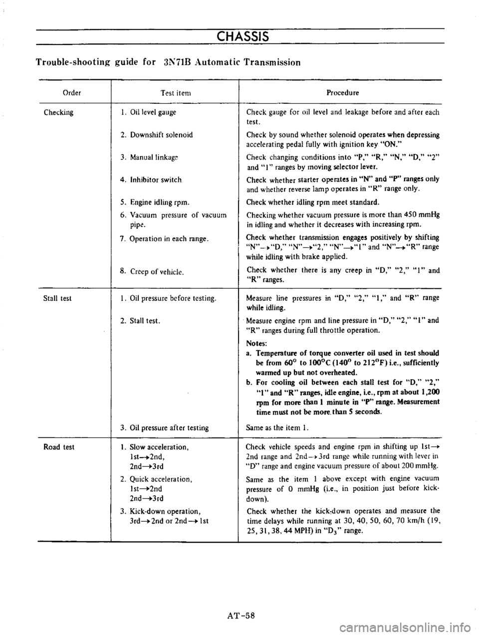
CHASSIS
Trouble
shooting
guide
for
3N71B
Automatic
Transmission
Order
Test
item
Checking
Oil
level
gauge
2
Downshift
solenoid
3
ManuaIlinkage
4
Inhibitor
switch
5
Engine
idling
rpm
6
Vacuum
pressure
of
vacuum
pipe
7
Operation
in
each
range
8
Creep
of
vehicle
Stall
lest
Oil
pressure
before
testing
2
Stall
test
3
Oil
pressure
after
testing
Road
test
Slow
acceleration
Ist
2nd
2nd
3rd
2
Quick
acceleration
Ist
2nd
2nd
3rd
3
Kick
down
operation
3rd
2nd
or
2nd
1st
Procedure
Check
gauge
for
oil
level
and
leakage
before
and
after
each
test
Check
by
sound
whether
solenoid
operates
when
depressing
accelerating
pedal
fully
with
ignition
key
ON
Check
changing
conditions
into
P
R
N
D
2
and
I
ranges
by
moving
selector
lever
Check
whether
starter
operates
in
N
and
tp
ranges
only
and
whether
reverse
lamp
operates
in
R
range
only
Check
whether
idling
rpm
meet
standard
Checking
whether
vacuum
pressure
is
more
than
450
mmHg
in
idling
and
whether
it
decreases
with
increasing
rpm
Check
whether
transmission
engages
positively
by
shifting
N
o
D
N
2
N
I
and
N
R
range
while
idling
with
brake
applied
Check
whether
there
is
any
creep
in
D
2
I
and
R
ranges
2
1
and
R
range
Measure
line
pressures
in
D
while
idling
Measure
engine
rpm
and
line
pressure
in
D
2
I
and
R
ranges
during
fullthrallIe
operation
Notes
a
Temperature
of
torque
converter
oil
used
in
test
should
be
from
600
to
lOOoC
1400
to
2120F
i
e
sufficiently
warmed
up
but
not
overheated
b
For
cooling
oil
between
each
stall
test
for
D
2
1
and
R
ranges
idle
engine
i
e
rpm
at
about
1
200
rpm
for
more
than
1
minute
in
P
range
Measurement
time
must
not
be
more
than
5
secon
Same
as
the
item
I
Check
vehicle
speeds
and
engine
rpm
in
shifting
up
1st
2nd
range
and
2nd
J
3rd
range
while
running
with
lever
in
D
range
and
engine
vacuum
pressure
of
about
200
mmHg
Same
as
the
item
1
above
except
with
engine
vacuum
pressure
of
0
mmHg
i
e
in
position
just
before
kick
down
Check
whether
the
kick
down
operates
and
measure
the
time
delays
while
running
at
30
40
50
60
70
km
h
19
25
31
38
44
MPH
in
D
range
AT
58
Page 95 of 513

Judgement
Components
Rust
Fig
h
Discoloring
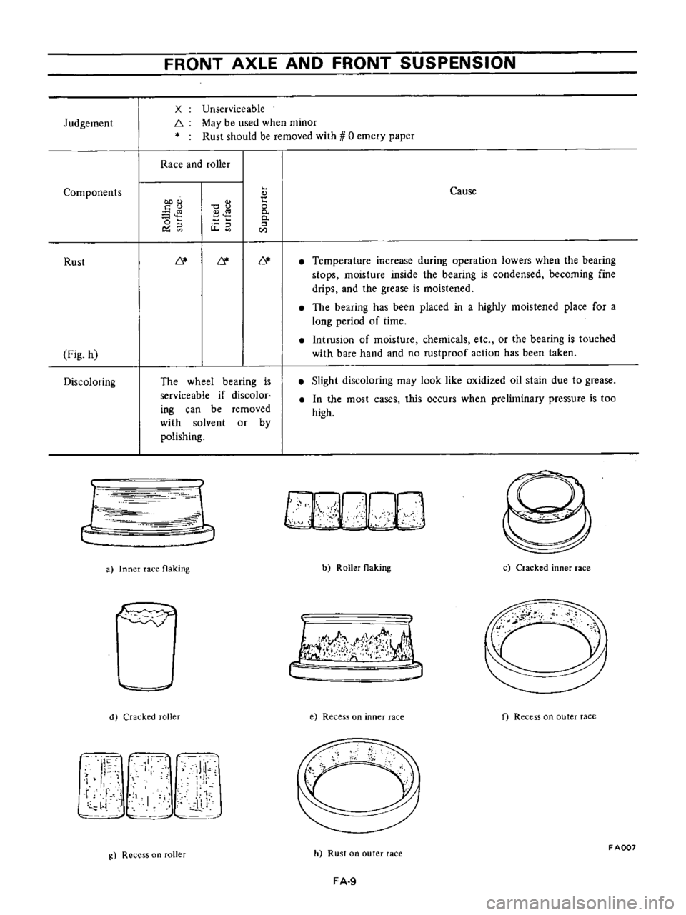
FRONT
AXLE
AND
FRONT
SUSPENSION
x
f
Unserviceable
May
be
used
when
minor
Rust
should
be
removed
with
0
emery
paper
Race
and
roller
00
u
o
o
Ou
u
The
wheel
bearing
is
serviceable
if
discolor
ing
can
be
removed
with
solvent
or
by
polishing
r
c
1
1
Ie
r
r
iJ
a
Inner
race
flaking
d
Cracked
roller
J
I
11
Ji
l
L
i
I
11
J
g
Recess
on
roller
o
0
0
CIl
Cause
Temperature
increase
during
operation
lowers
when
the
bearing
stops
moisture
inside
the
bearing
is
condensed
becoming
fine
drips
and
the
grease
is
moistened
The
bearing
has
been
placed
in
a
highly
moistened
place
for
a
long
period
of
time
Intrusion
of
moisture
chemicals
etc
or
the
bearing
is
touched
with
bare
hand
and
no
rustproof
action
has
been
taken
Slight
discoloring
may
look
like
oxidized
oil
stain
due
to
grease
In
the
most
cases
this
occurs
when
preliminary
pressure
is
too
high
b
Roller
flaking
c
Cracked
inner
race
I
lJ
f
t
j
e
Recess
on
inner
race
f
Recess
on
outer
race
cc
h
Rust
on
outer
race
FADD7
FA
9
Page 253 of 513

BODY
METERS
AND
GAUGES
CONTENTS
CLUSTER
LID
Oescri
ption
Removal
SPEEDOMETER
Replacement
FUEL
GAUGE
AND
TEMPERATURE
GAUGE
Description
Replacement
BE
1B
BE
18
BE
18
BE
19
BE
19
BE
19
BE
19
BE
20
CLUSTER
LID
Description
The
cluster
lid
holds
various
rneters
indicators
and
clock
located
around
the
speedorneter
Printed
circuit
board
is
used
at
the
back
of
the
meter
as
shown
in
Figure
BE
38
and
the
printed
circuit
board
is
connected
with
multiple
connectors
Thus
the
meters
Can
be
inspected
and
serviced
extremely
easily
Except
for
the
speed
ometer
all
rneters
are
operated
electrically
The
fuel
gauge
and
therrnometer
are
very
reliable
and
they
are
equipped
with
bimetal
devices
F
a
o
ill
I
1
a
a
Fig
BE
34
Combination
meters
Removal
Disconnect
the
battery
terminal
depressing
the
OIL
PRESSURE
AND
IGNITION
WARNING
LAMPS
HAND
BRAKE
WARNING
LAMP
BULB
SPECIFICATIONS
TROUBLE
DIAGNOSES
AND
CORRECTIONS
Speedometer
Thermometer
and
fuel
meter
Oil
pressure
and
ignition
warning
lamps
BE
20
BE
21
BE
21
BE
22
BE
22
BE
23
BE
25
windshield
wiper
switch
lighting
switch
and
choke
lever
knobs
turn
them
counterclockwise
to
remove
Remove
the
escutcheon
2
Inserting
your
hand
into
back
of
the
cluster
lid
disconnect
the
cigarette
lighter
cable
and
turn
and
remove
the
cigarette
lighter
outer
case
3
Remove
the
radio
and
heater
control
knobs
4
Remove
the
shell
cover
from
the
steering
tube
loosen
the
screws
used
to
secure
the
meter
housing
to
the
instrument
panel
and
remove
the
cluster
lid
5
Pull
out
the
l2
pole
round
shape
connector
and
remove
the
speedometer
cable
union
nut
6
Remove
the
cluster
lid
from
the
instrument
panel
Fig
BE
35
Removing
clllSter
jd
BE
18
Page 254 of 513

BODY
ELECTRICAL
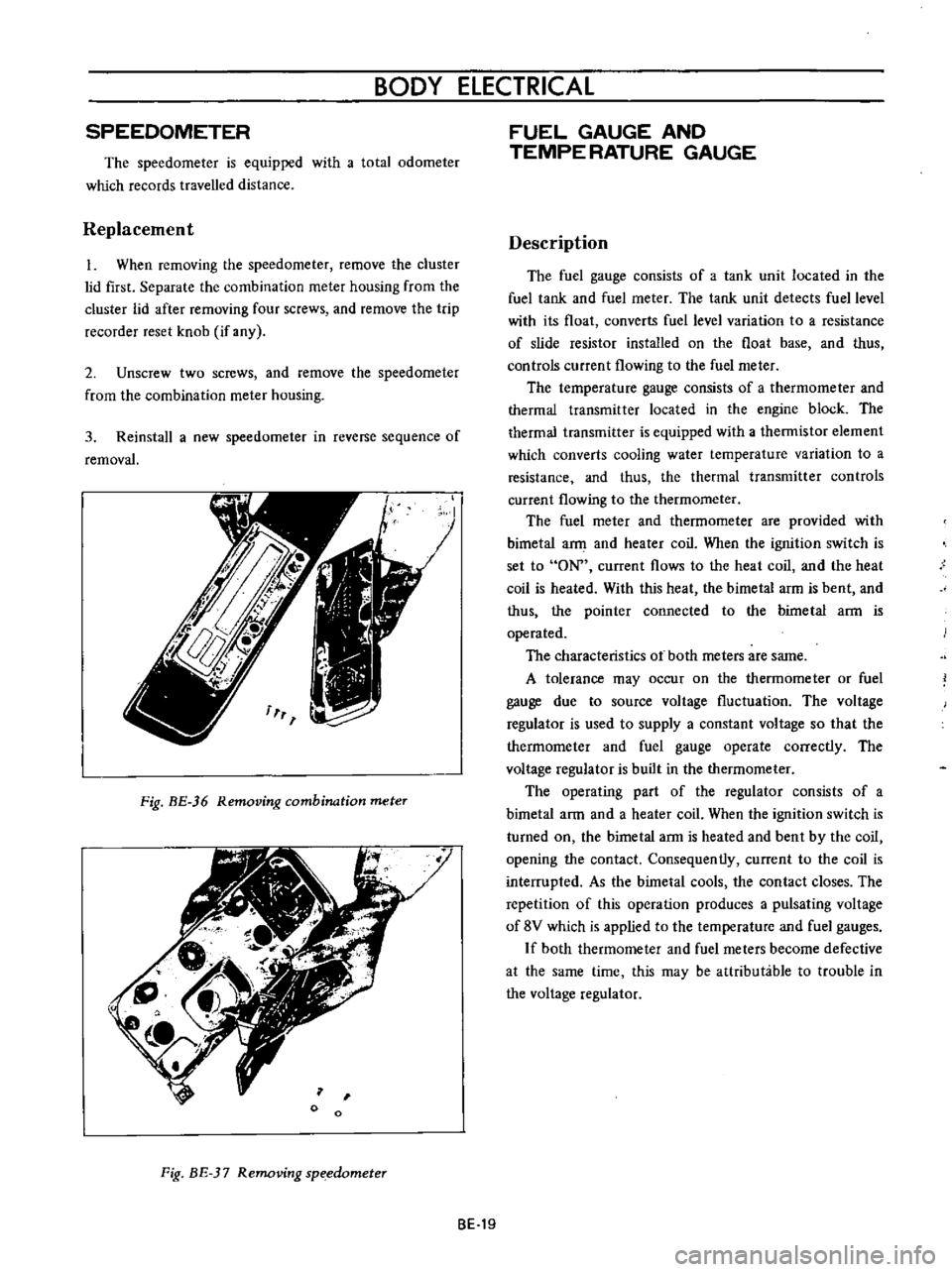
SPEEDOMETER
The
speedometer
is
equipped
with
a
total
odometer
which
records
travelled
distance
Replacement
1
When
removing
the
speedometer
remove
the
cluster
lid
first
Separate
the
combination
meter
housing
from
the
cluster
lid
after
removing
four
screws
and
remove
the
trip
recorder
reset
knob
if
any
2
Unscrew
two
screws
and
remove
the
speedometer
from
the
combination
meter
housing
3
Reinstall
a
new
speedometer
in
reverse
sequence
of
removal
Fig
BE
36
Removing
combination
meter
o
Fig
BE
37
Removing
sp
edometer
FUEL
GAUGE
AND
TEMPE
RATURE
GAUGE
Description
The
fuel
gauge
consists
of
a
tank
unit
located
in
the
fuel
tank
and
fuel
meter
The
tank
unit
detects
fuel
level
with
its
float
converts
fuel
level
variation
to
a
resistance
of
slide
resistor
installed
on
the
float
base
and
thus
controls
current
flowing
to
the
fuel
meter
The
temperature
gauge
consists
of
a
thermorneter
and
thermal
transmitter
located
in
the
engine
block
The
thermal
transmitter
is
equipped
with
a
thermistor
element
which
converts
cooling
water
temperature
variation
to
a
resistance
and
thus
the
thermal
transmitter
controls
current
flowing
to
the
thermometer
The
fuel
rneter
and
thermometer
are
provided
with
bimetal
a
and
heater
coil
When
the
ignition
switch
is
set
to
ON
current
flows
to
the
heat
coil
and
the
heat
coil
is
heated
With
this
heat
the
bimetal
arm
is
bent
and
thus
the
pointer
connected
to
the
bimetal
ann
is
operated
The
characteristics
ot
both
meters
are
same
A
tolerance
may
occur
on
the
thermometer
or
fuel
gauge
due
to
source
voltage
fluctuation
The
voltage
regulator
is
used
to
supply
a
constant
voltage
so
that
the
therrnorneter
and
fuel
gauge
operate
correctly
The
voltage
regulator
is
built
in
the
thermometer
The
operating
part
of
the
regulator
consists
of
a
bimetal
arm
and
a
heater
coil
When
the
ignition
switch
is
turned
on
the
birnetal
arm
is
heated
and
bent
by
the
coil
opening
the
contact
Consequently
current
to
the
coil
is
interrupted
As
the
bimetal
cools
the
contact
closes
The
repetition
of
this
operation
produces
a
pulsating
voltage
of
8V
which
is
applied
to
the
ternperature
and
fuel
gauges
If
both
thermometer
and
fuel
meters
become
defective
at
the
same
time
this
may
be
attributable
to
trouble
in
the
voltage
regulator
BE
19
Page 255 of 513

BODY
REGULATOR
FUSE
M
TEMPE
RATURE
GAUGE
IGNITION
SWITCH
Lf
I
iT
Ji
1M
THERMAL
TRANSMITTER
I
J
0
I
GAUGE
TANK
UNIT
FUEL
TANK
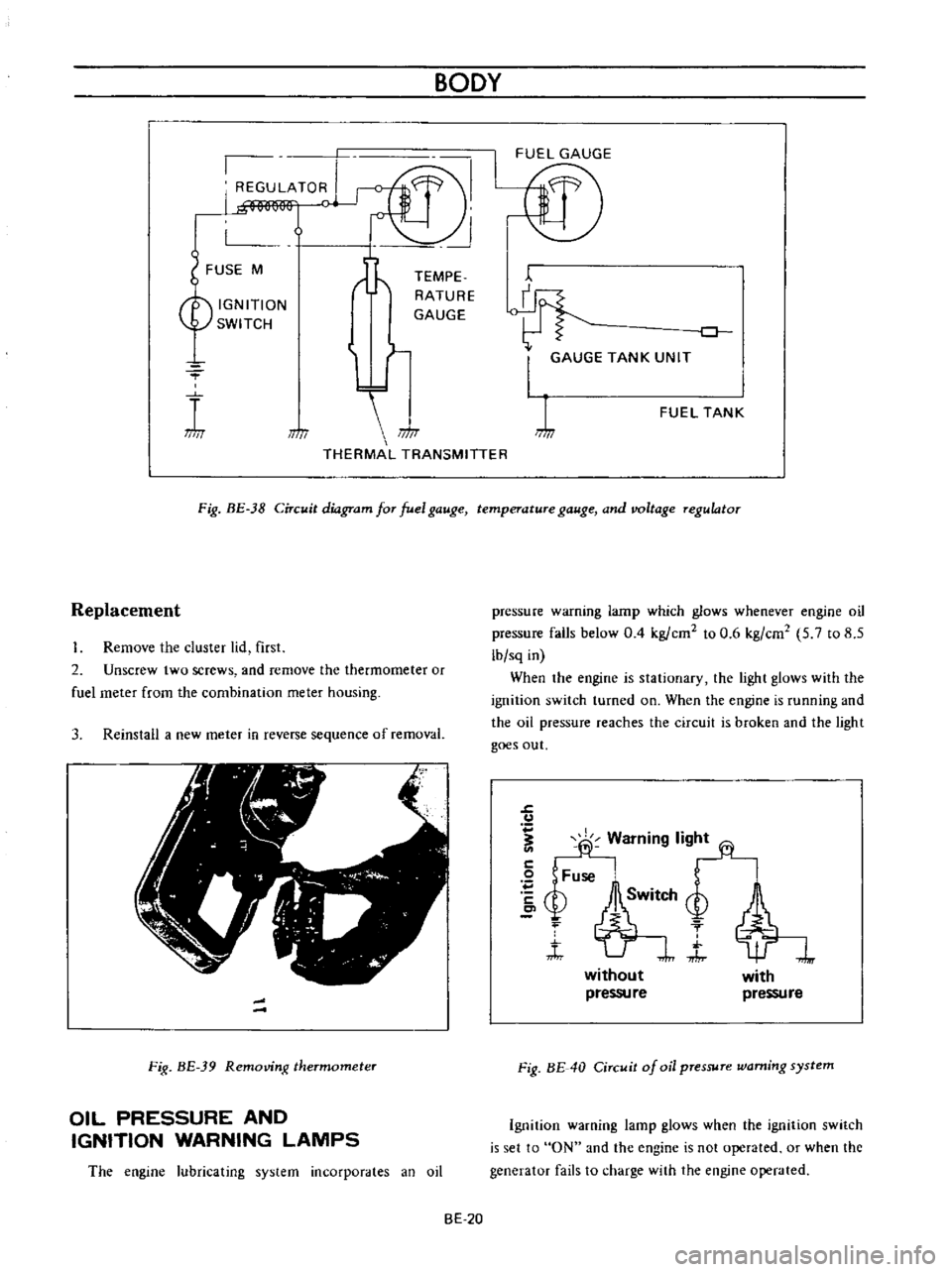
Fig
BE
38
Circuit
diagram
for
fuel
gauge
temperature
gauge
and
voltage
regulator
Replacement
Remove
the
cluster
lid
first
2
Unscrew
two
screws
and
remove
the
thermometer
or
fuel
meter
from
the
combination
meter
housing
3
Reinstall
a
new
meter
in
reverse
sequence
of
removal
Fig
BE
39
Removing
thermometer
OIL
PRESSURE
AND
IGNITION
WARNING
LAMPS
The
engine
lubricating
system
incorporates
an
oil
pressure
warning
lamp
which
glows
whenever
engine
oil
pressure
falls
below
0
4
kg
ern
to
0
6
kg
em
5
7
to
8
5
lb
sq
in
When
the
engine
is
stationary
the
light
glows
with
the
ignition
switch
turned
on
When
the
engine
is
running
and
the
oil
pressure
reaches
the
circuit
is
broken
and
the
light
goes
out
J
u
fj
Warning
lig
2
Fuse
bSM
Q
f
t
J
without
pressu
re
with
pressure
Fig
BE
40
Circuit
of
oil
pressure
warning
system
Ignition
warning
lamp
glows
when
the
ignition
switch
is
set
to
ON
and
the
engine
is
not
operated
or
when
the
generator
fails
to
charge
with
the
engine
operated
BE
20