1973 DATSUN B110 oil temperature
[x] Cancel search: oil temperaturePage 306 of 513

EMISSION
CONTROL
AND
TUNE
UP
EMISSION
CONTROL
SYSTEM
AN
D
ENGINE
TUNE
UP
CONTENTS
BASIC
MECHANICAL
SYSTEM
ET
Checking
and
adjusting
dash
pot
Adjusting
intake
and
exhaust
valve
automatic
transmission
model
only
ET
9
clearances
ET
1
Checking
carburetor
return
spring
ET
9
Checking
and
adjustin9
drive
belt
ET
2
Checking
choke
mechanism
choke
valve
Retightening
cylinder
head
bolts
manifold
and
linkagel
ET
9
nuts
and
carburetor
securing
nuts
ET
2
Checking
anti
dieseling
solenoid
ET
9
Checking
engine
oil
ET
2
Replacing
fuel
filter
ET
10
Replacing
oil
filter
ET
3
Checking
fuel
lines
hoses
pipings
Changing
engine
coolant
L
L
C
ET
3
connections
etc
ET10
Checking
cooling
system
hoses
and
THROTTLE
OPENER
CONTROL
SYSTEM
ET
10
connections
ET
4
Checking
and
adjusting
throttle
opener
ET
13
Checking
vacuum
fittings
hoses
and
TRANSMISSION
CONTROLLED
VACUUM
connections
ET
4
ADVANCE
SYSTEM
ET
17
Checking
engine
compression
ET
4
Checking
electrical
advance
control
system
ET
19
Checking
exhaust
manifold
heat
control
AUTOMATIC
TEMPERATURE
CONTROL
AIR
valve
ET
5
CLEANER
A
T
C
AIR
CLEANER
ET
20
IGNITION
AND
FUEL
SYSTEM
ET
5
Replacing
carburetor
air
cleaner
filter
ET
20
Checking
battery
ET
5
Checking
hot
air
control
valve
ET
20
Checking
and
adjusting
ignition
timing
ET
5
CRANKCASE
EMISSION
CONTROL
Checking
or
replacing
distributor
breaker
SYSTEM
ET
22
point
condenser
and
spark
plugs
ET
6
Checking
or
replacing
PCV
valve
ET
23
Checking
distributor
ignition
wiring
and
Checking
ventilation
hoses
ET
23
ignition
coil
ET
7
EVAPORATIVE
EMISSION
CONTROL
Checking
distributor
cap
and
rotor
ET
7
SYSTEM
ET
23
Adjusting
carburetor
id
Ie
rpm
and
Checking
engine
compartment
hose
mixture
ratio
ET
8
connections
and
fuel
vapor
control
valves
ET
23
Checking
fuel
tank
vacuum
relief
valve
operation
ET
24
BASIC
MECHANICAL
SYSTEM
1
Start
engine
and
run
it
until
it
is
heated
to
operating
temperature
or
at
least
more
than
800C
I760F
of
engine
oil
temperature
then
stop
engine
Adjusting
intake
and
exhaust
valve
clearances
Valve
clearance
adjustment
should
be
made
while
engine
is
stationary
To
adjust
proceed
as
follows
2
Rotate
crankshaft
to
bring
No
1
cylinder
in
top
dead
center
on
its
compression
stroke
3
Remove
valve
rocker
cover
to
gain
access
to
valve
ET
1
Page 308 of 513
EMISSION
CONTROL
AND
TUNE
UP
Capacity
Maximum
3
3
L
X
US
gal
y
Imp
gal
2
3
L
US
gal
f
Imp
gal
Minimum
Make
sure
that
engine
oil
is
not
deteriorated
with
cooling
water
or
gasoline
Drain
and
refill
the
oil
if
necessary
Notes
a
A
milky
oil
indicates
the
presence
of
cooling
water
Find
the
cause
for
necessary
corrective
action
b
Oil
with
extremely
low
viscosity
indicates
dilution
with
gasoline
2
Check
oil
level
If
found
below
L
mark
refill
to
H
mark
on
gauge
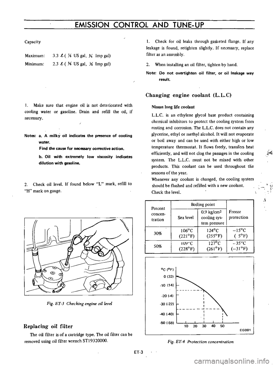
Fig
ET
3
Checking
engine
oil
level
Replacing
oil
filter
The
oil
ftIter
is
of
a
cartridge
type
The
oil
filter
can
be
removed
using
oil
ftIter
wrench
STl9320000
Check
for
oil
leaks
through
gasketed
flange
If
any
leakage
is
found
retighten
slightly
If
necessary
replace
filter
as
an
assembly
2
When
installing
an
oil
filter
tighten
by
hand
Note
Do
not
overtighten
oil
filter
or
oil
leakage
way
result
Changing
engine
coolant
L
L
C
Nissan
long
life
coolant
LLC
is
an
ethylene
glycol
base
product
containing
chemical
inhibitors
to
protect
the
cooling
system
from
rusting
and
corrosion
The
L
L
C
does
not
contain
any
glycerine
ethyl
or
methyl
alcohol
It
will
not
evaporate
or
boil
away
and
can
be
used
with
either
high
or
low
temperature
thermostat
It
flows
freely
transfers
heat
efficiently
and
will
not
clog
the
passages
in
the
cooling
system
The
LL
C
must
not
be
mixed
with
other
products
This
coolant
can
be
used
throughout
tlie
seasons
of
the
year
Whenever
any
coolant
is
changed
the
cooling
system
should
be
flushed
and
refilled
with
a
new
coolant
Check
the
level
J
Percent
Boiling
point
0
9
kgfcm2
Freeze
concen
tration
Sea
level
cooling
sys
protection
tern
pressure
30
1060
C
I
240C
15OC
221OF
255OF
5OF
50
IUY
C
1270C
35
C
2280
F
2610F
3IOF
DC
OF
0
321
10
14
20141
50
58
I
I
I
I
1
I
I
1
30
1
22
40
401
40
10
30
50
20
EGOOl
Fig
ET
4
Protection
concentration
ET
3
Page 327 of 513
ENGINE
6
Start
the
engine
and
continue
idling
as
described
under
paragraphs
I
2
and
3
above
When
several
minutes
have
passed
and
the
valve
is
partially
opened
read
the
thermister
indication
It
is
correct
if
the
reading
falls
between
380C
1000
F
and
550C
1300
F
If
the
reading
is
abnormal
replace
the
sensor
7
On
the
engine
equipped
with
an
idle
compensator
as
service
option
do
as
follows
before
replacing
the
sensor
Clog
hose
on
idle
compensator
side
by
twisting
or
clamping
it
and
check
the
temperature
as
given
in
paragraphs
5
and
6
above
If
the
thermometer
shO
vs
correct
temperature
replace
the
idle
compensa
tOf
if
the
reading
is
abnormal
replace
the
sensor
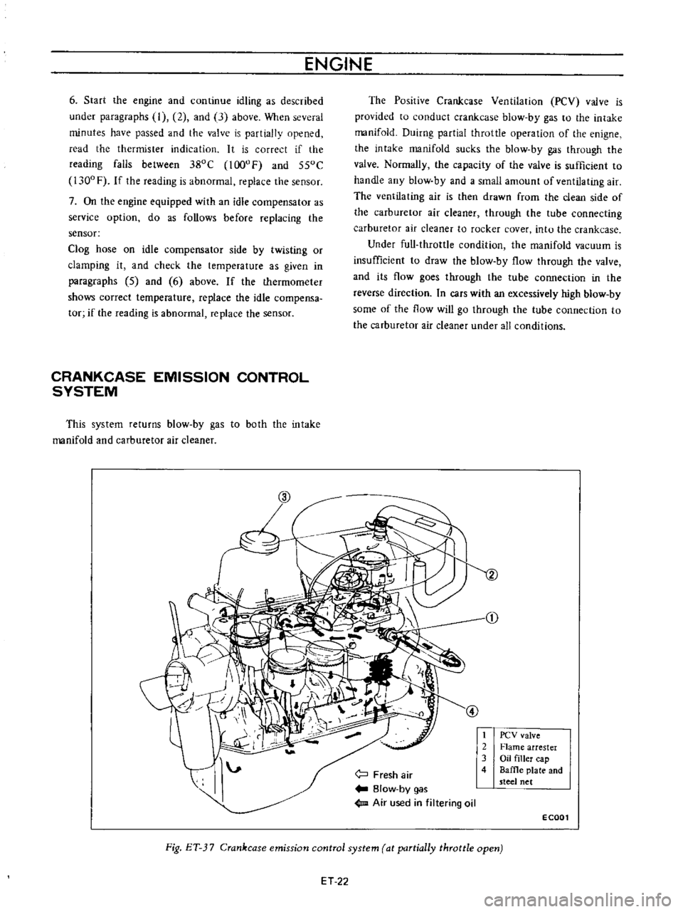
CRANKCASE
EMISSION
CONTROL
SYSTEM
This
system
returns
blow
by
gas
to
both
the
intake
manifold
and
carburetor
air
cleaner
The
Posirive
Crankcase
Ventilation
PCV
valve
is
provided
to
conduct
crankcase
blow
by
gas
to
the
intake
manifold
Duirng
partial
throttle
operation
of
the
enigne
the
intake
manifold
sucks
the
blow
by
gas
through
the
valve
Normally
the
capacity
of
the
valve
is
sufficient
to
handle
any
blow
by
and
a
small
amount
of
ventilating
air
The
ventilating
air
is
then
drawn
from
the
clean
side
of
the
carburetor
air
cleaner
through
the
tube
connecting
carburetor
air
cleaner
to
rocker
cover
intu
the
crankcase
Under
full
throttle
condition
the
manifold
vacuum
is
insufficient
to
draw
the
blow
by
flow
through
the
valve
and
its
flow
goes
through
the
tube
connection
in
the
reverse
direction
In
cars
with
an
excessively
high
blow
by
some
of
the
flow
will
go
through
the
tube
connection
to
the
carburetor
air
cleaner
under
all
conditions
j
Fresh
air
Blow
by
gas
1m
Air
used
in
filtering
oil
t
2
3
4
PCV
valve
Flame
arrester
Oil
filler
cap
Baffle
plate
and
steel
net
ECOOl
Fig
ET
3
7
Crankcase
emission
control
system
at
partially
throttle
open
ET
22
Page 331 of 513

ENGINE
Spark
plugs
Cap
mm
in
0
8
to
0
9
0
03110
0
035
Idle
CO
ldie
speed
Manual
transmission
rpm
rpm
1
5
to
5
800
1
5
to
5
650
in
D
position
Automatic
transmission
Dash
pot
Setting
engine
speed
rpm
1
900
to
2
000
Throttle
opener
at
sea
level
Setting
vacuwn
pressure
Manual
transmission
Automatic
transmission
Setting
engine
speed
no
load
Servo
diaphragm
full
stroke
rpm
mm
in
500
to
540
19
7
to
21
3
480
to
520
18
9
to
20
5
1
650
to
1
850
5
0
1969
mmHg
in
Hg
mmHg
in
Hg
Theono
switch
Temperature
rises
from
low
to
high
oC
0
F
above
5
41
Flow
guide
valve
Opera
ting
pressure
mmHg
in
Hg
10
0
4
TROUBLE
DIAGNOSES
AND
CORRECTIONS
Troubles
Possible
causes
Remedies
CANNOT
CRANK
ENGINE
OR
SLOW
CRANKING
Improper
grade
oiL
Replace
with
proper
grade
oiL
Discharged
battery
Charge
battery
Defective
battery
Replace
Loosen
fan
belt
Adjust
Trouble
in
charge
system
Inspect
charge
system
Wiring
connection
trouble
in
starting
circuit
Correct
Defective
starter
switch
Repair
or
replace
Defective
starter
motor
Repair
or
replace
ET
26
I
Page 334 of 513

IMPROPER
ENGINE
IDLING
Fuel
system
in
trouble
Low
compression
Others
Ignition
system
in
trouble
Engine
idle
too
fa
t
ENGINE
POWER
NOT
UP
TO
NORMAL
4
w
compression
Ignition
system
in
trouble
Fuel
system
in
trouble
EMISSION
CONTROL
AND
TUNE
UP
Clogged
or
damaged
carburetor
jets
Incorrect
carburetor
adjustment
idle
speed
idle
mixture
Clogged
air
cleaner
Defective
gaskets
of
manifolds
or
carburetor
insulator
Improper
float
level
adjustment
Incorrect
valve
clearance
Extremely
low
revolution
Incorrect
basic
ignition
timing
Incorrect
automatic
teinperature
control
air
cleaner
Defect
or
malfunction
of
ignition
system
spark
plug
high
tension
cable
breaker
point
ignition
coil
etc
Trouble
in
throttle
link
and
cable
Incorrect
throttle
opener
adjustment
Trouble
in
PCV
valve
Trouble
in
automatic
choke
Defect
or
malfunction
of
ignition
system
spark
plug
high
tension
cable
breaker
point
ignition
coil
etc
Incorrect
ignition
timing
Defective
spark
plugs
Defective
distributor
points
Malfunction
of
choke
system
Clogged
fuel
pipe
ET
29
Clean
or
replace
Adjust
idle
speed
mixture
Replace
element
Replace
gasket
Adjust
Previously
mentioned
Adjust
Adjust
idie
rpm
Adjust
ignition
timing
Adjust
automatic
temperature
control
air
cleaner
Adjust
or
replace
ignition
system
Check
throttle
link
and
cable
Adjust
throttle
opener
Replace
PCV
valve
Adjust
automatic
choke
Adjust
or
replace
ignition
system
Previously
mentioned
Adjust
Clean
adjust
or
replace
plugs
Dress
or
replace
points
Check
con
denser
Adjust
Clean
Page 414 of 513
Troubles
Improper
idling
Rough
engine
idle
or
engine
stop
Engine
idle
too
fast
Engine
hesitation
FUEl
SYSTEM
Possible
causes
ruel
strainer
clogged
Vacuum
jet
clogged
Power
valve
operated
improperly
Slow
jet
clogged
Each
throttle
valve
does
not
close
Secondary
throttle
valve
operated
im
properly
Each
throttle
valve
shaft
wear
Packing
between
manifold
and
carburetor
defective
Fuel
overflows
Incorrect
carburetor
adjustment
idle
speed
idle
mixture
choke
setting
Incorrect
basic
ignition
timing
Incorrect
automatic
temperature
control
air
cleaner
Defect
or
malfunction
of
ignition
system
spark
plug
high
tension
cable
breaker
point
ignition
coil
etc
Trouble
in
throttle
link
and
cable
Incorrect
throttle
opener
adjustment
Trouble
in
PCV
valve
Trouble
in
automatic
choke
Defect
or
malfunction
of
ignition
system
spark
plug
high
tension
cable
breaker
point
ignition
coil
etc
Each
main
jet
slow
jet
clogged
By
pass
hole
idle
passage
clogged
Emulsion
tube
clogged
EF
23
Remedies
Clean
Clean
Adjust
Clean
Adjust
Overhaul
and
clean
Replace
Replace
tightening
See
the
first
item
Adjust
idle
speed
mixture
and
timing
Adjust
ignition
timing
Adjust
automatic
temperature
control
air
cleaner
Adjust
or
replace
ignition
system
Check
throttle
link
and
cable
Adjust
throttle
opener
Replace
PCV
valve
Adjust
auotmatic
choke
Adjust
or
replace
ignition
system
Clean
Clean
tube
Clean
Page 423 of 513
ENGINE
ElECTRICAL
SYSTEM
5
If
the
specific
gravity
is
above
1
260
200C
or
680F
after
charging
adjust
it
by
adding
distilled
water
6
Keep
any
open
flame
away
from
the
place
where
the
battery
is
being
charged
7
Replace
vent
plugs
and
clean
the
upper
face
of
the
battery
after
charging
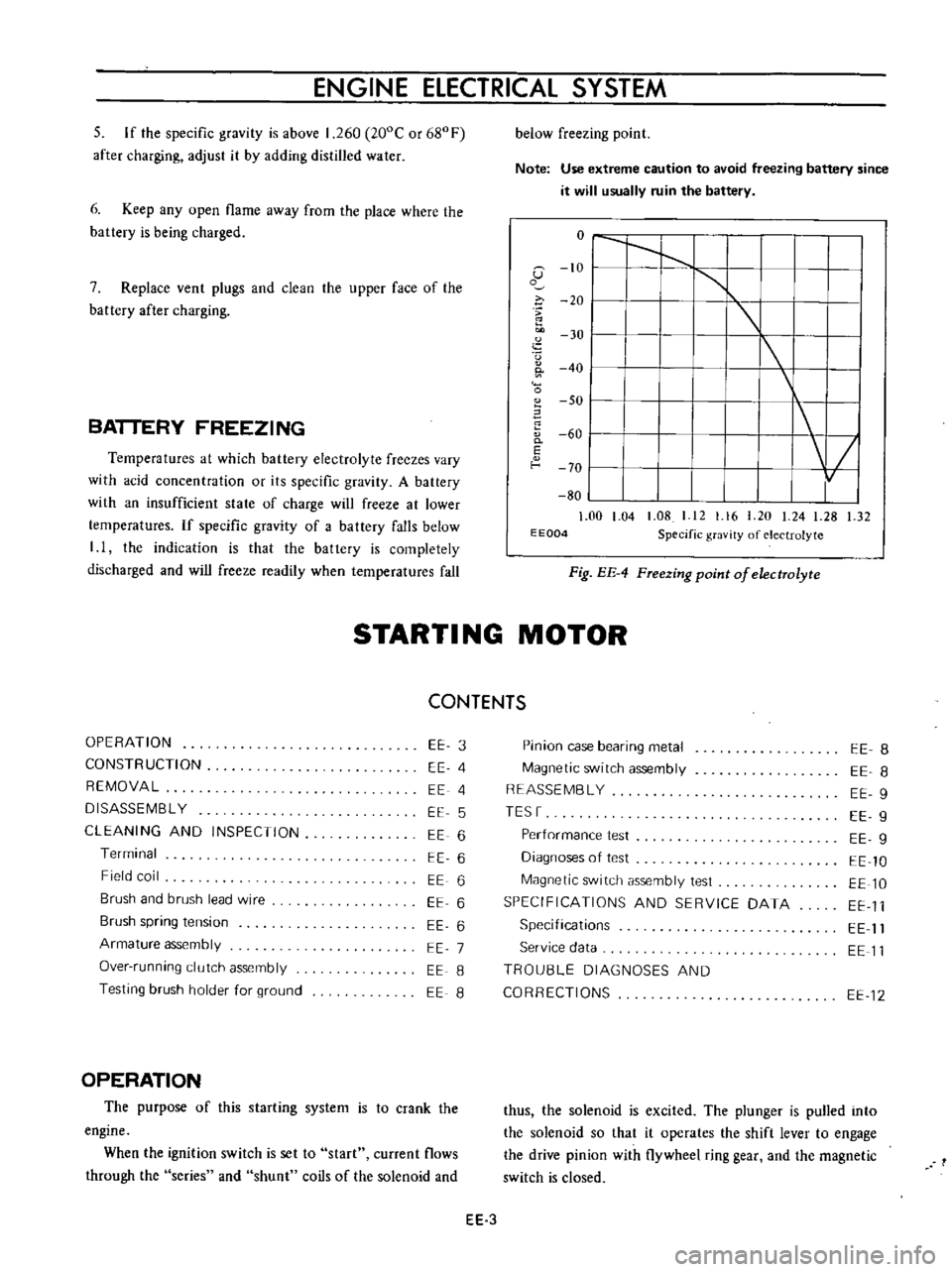
BATTERY
FREEZING
Temperatures
at
which
battery
electrolyte
freezes
vary
with
acid
concentration
or
its
specific
gravity
A
battery
with
an
insufficient
state
of
charge
will
freeze
at
lower
temperatures
If
specific
gravity
of
a
battery
falls
below
I
I
the
indication
is
that
the
battery
is
completely
discharged
and
will
freeze
readily
when
temperatures
fall
below
freezing
point
Note
Use
extreme
caution
to
avoid
freezing
battery
since
it
will
usually
ruin
the
battery
o
I
I
1
G
10
I
1
o
i
20
I
u
30
I
I
0
40
I
0
SO
I
60
0
I
E
f
o
70
I
80
1
00
1
04
1
08
I
12
1
16
20
24
1
28
1
32
E
E004
Specific
gravity
of
electrolyte
Fig
EE
4
FTeezing
point
of
electrolyte
STARTI
NG
MOTOR
CONTENTS
OPERATION
CONSTRUCTION
REMOVAL
DISASSEMBL
Y
CLEANING
AND
INSPECTION
Terminal
Field
coil
Brush
and
brush
lead
wire
Brush
spring
tension
Armature
assembly
Over
running
clutch
assembly
Testing
brush
holder
for
ground
EE
3
EE
4
EE
4
EE
5
EE
6
EE
6
EE
6
EE
6
EE
6
EE
7
EE
8
EE
8
OPERATION
The
purpose
of
this
starting
system
is
to
crank
the
engine
When
the
ignition
switch
is
set
to
start
current
flows
through
the
series
and
shunt
coils
of
the
solenoid
and
Pinion
case
bearing
metal
Magnetic
switch
assembly
REASSEMBL
Y
TESr
Performance
test
Diagnoses
of
test
Magnetic
switch
assembly
test
SPECIFICATIONS
AND
SERVICE
DATA
Specifications
Service
data
TROU8LE
DIAGNOSES
AND
CORRECTIONS
EE
8
EE
8
EE
9
EE
9
EE
g
EE
10
EE
10
EE
11
EE
11
EE
11
EE
12
thus
the
solenoid
is
excited
The
plunger
is
pulled
into
the
solenoid
so
that
it
operates
the
shift
lever
to
engage
the
drive
pinion
with
flywheel
ring
gear
and
the
magnetic
switch
is
closed
EE
3
Page 439 of 513
ENGINE
ELECTRICAL
SYSTEM
Note
Use
care
in
handling
diode
assembly
to
prevent
an
undue
stress
on
it
INSPECTION
AND
REPAIR
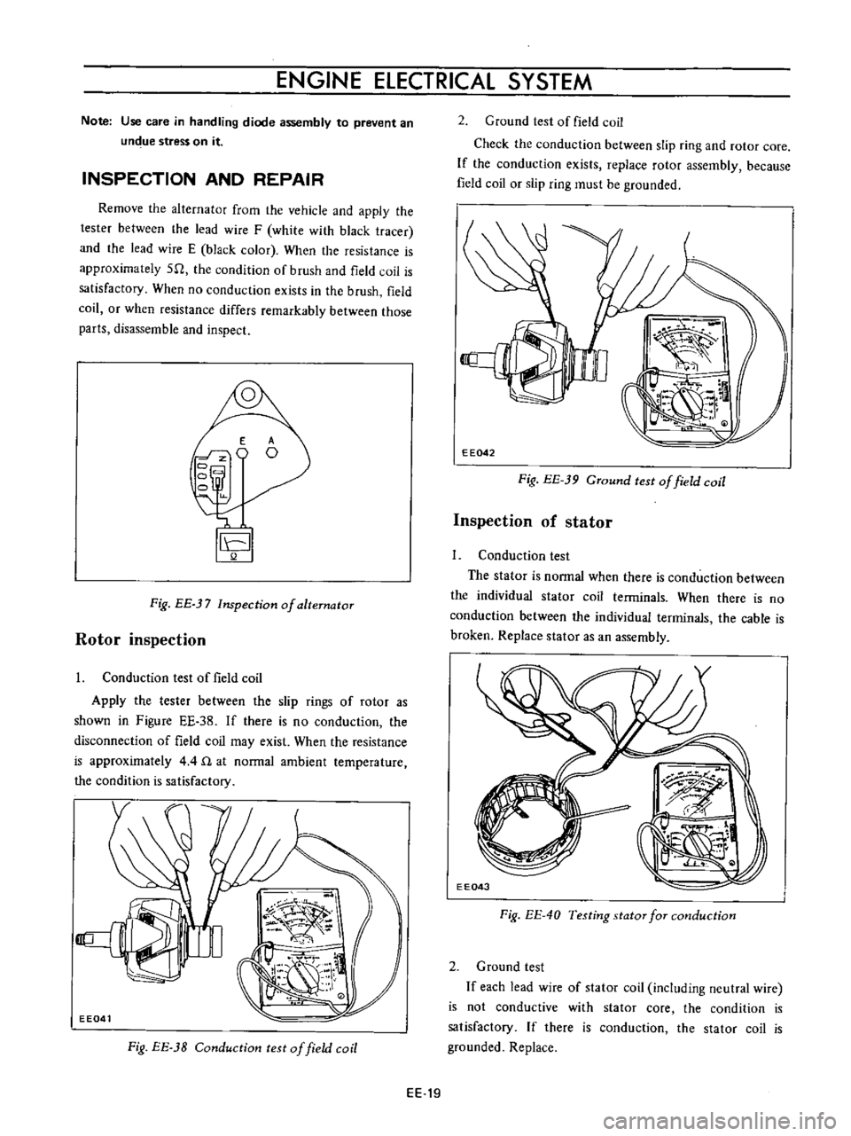
Remove
the
alternator
from
the
vehicle
and
apply
the
tester
between
the
lead
wire
F
white
with
black
tracer
and
the
lead
wire
E
black
color
When
the
resistance
is
approximately
511
the
condition
of
brush
and
field
coil
is
satisfactory
When
no
conduction
exists
in
the
brush
field
coil
or
when
resistance
differs
remarkably
between
those
parts
disassemble
and
inspect
E
o
Fig
BE
37
Inspection
of
alternator
Rotor
inspection
I
Conduction
test
of
field
coil
Apply
the
tester
between
the
slip
rings
of
rotor
as
shown
in
Figure
EE
38
If
there
is
no
conduction
the
disconnection
of
field
coil
may
exist
When
the
resistance
is
approximately
4
4
n
at
normal
ambient
temperature
the
condition
is
satisfactory
Fig
EE
3B
Conduction
test
of
field
coil
2
Ground
test
of
field
coil
Check
the
conduction
between
slip
ring
and
rotor
core
If
the
conduction
exists
replace
rotor
assembly
because
field
coil
or
slip
ring
must
be
grounded
EE042
Fig
EE
39
GTound
test
of
field
coil
Inspection
of
stator
1
Conduction
test
The
stator
is
normal
when
there
is
conduction
between
the
individual
stator
coil
terminals
When
there
is
no
conduction
between
the
individual
terminals
the
cable
is
broken
Replace
stator
as
an
assembly
EE043
Fig
EE
40
Testing
stator
for
cmlduction
2
Ground
test
If
each
lead
wire
of
stator
coil
including
neutral
wire
is
not
conductive
with
stator
core
the
condition
is
satisfactory
If
there
is
conduction
the
stator
coil
is
grounded
Replace
EE
19