Page 126 of 513

CHASSIS
DESCRIPTION
The
Datsun
1200
series
new
models
adopt
a
hydraulic
brake
Dis
brake
or
two
leading
shoe
type
drum
brake
is
used
for
the
front
wheels
and
leading
trailing
shoe
type
drum
brake
is
used
for
the
rear
wheels
With
adoption
of
the
disc
brake
safety
at
high
speed
range
driving
is
further
improved
For
the
master
cylinder
either
single
type
or
tandem
type
is
used
There
are
two
types
of
tandem
type
master
cylinder
one
is
for
disc
brake
and
the
other
for
drum
brake
Under
the
standard
specifications
h0wever
the
tandem
type
master
cylinder
is
used
for
disc
brake
and
single
type
is
used
for
drum
brake
The
tandem
master
cylinder
provides
a
dual
brake
system
improving
safety
The
hand
brake
is
of
a
mechanical
type
which
brakes
the
rear
wheels
through
the
control
lever
and
steel
wire
The
control
lever
is
located
between
the
driver
and
assistant
seats
and
can
be
operated
easily
BRAKE
PEDAL
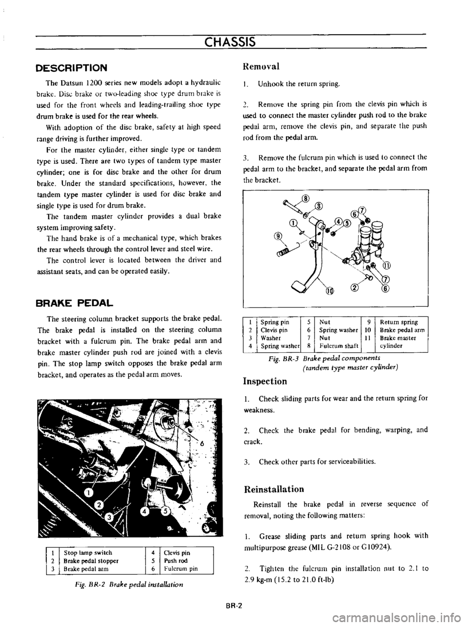
The
steering
colunm
bracket
supports
the
brake
pedaL
The
brake
pedal
is
instaUed
on
the
steering
column
bracket
with
a
fulcrum
pin
The
brake
pedal
arm
and
brake
master
cylinder
push
rod
are
joined
with
a
clevis
pin
The
stop
lamp
switch
opposes
the
brake
pedal
arm
bracket
and
operates
as
the
pedal
arm
moves
t
2
3
Stop
lamp
switch
Brake
pedal
stopper
Brake
pedal
arm
4
Clevis
pin
5
Push
rod
6
Fulcrum
pin
Fig
BR
2
Brake
pedal
installation
Removal
Unhook
the
rerum
spring
Remove
the
spring
pin
from
the
clevis
pin
which
is
used
to
connect
the
master
cylinder
push
rod
to
the
brake
pedal
arm
remove
the
clevis
pin
and
separate
the
push
rod
from
the
pedal
arm
3
Remove
the
fulcrum
pin
which
is
used
to
connect
the
pedal
arm
to
the
bracket
and
separate
the
pedal
arm
from
the
bracket
@
mm
l6
qf
@
@
t
Spring
pin
5
Nut
9
Return
spring
2
Clevis
pin
6
Spring
washer
10
Brake
pedal
arm
3
Washer
7
Nut
It
Brake
master
4
Spring
lasher
8
Fulcrum
shaft
cylinder
Fig
BR
3
Brake
pedal
components
tandem
type
master
cylinder
Inspection
1
Check
sliding
parts
for
wear
and
the
return
spring
for
weakness
2
Check
the
brake
pedal
for
bending
warping
and
crack
3
Check
other
parts
for
serviceabilities
Reinstallation
Reinstall
the
brake
pedal
in
reverse
sequence
of
removal
noting
the
following
matters
1
Grease
sliding
parts
and
retum
spring
hook
with
multipurpose
grease
MIL
G
2108
or
G
10924
2
Tighten
the
fulcrum
pin
installation
nut
to
2
1
to
2
9
kg
m
15
2
to
21
0
ft
lb
BR
2
Page 231 of 513
j
L
CD
1
II
r
1
P
r
4vc
V
4
I
o
@
@
c
ID
I
HEAD
REST
OPTION
When
installing
head
rest
on
front
seat
remove
the
plug
on
the
seat
back
and
insert
the
head
rest
supports
into
the
holes
Fig
BF
86
Head
rest
BODY
SEAT
BELT
The
two
front
seat
belts
are
of
a
three
point
type
consisting
of
lap
and
shoulder
belts
The
two
rear
seat
belts
are
of
a
tow
point
type
The
lap
belts
of
all
seats
are
provided
with
automatic
locking
retractor
In
the
front
automatic
locking
retaractor
a
belt
switch
retractor
switch
micro
switch
for
the
seat
belt
warning
system
is
built
in
Notes
a
DO
NOT
attempt
repairs
on
lap
belt
retractor
mechanisms
Replace
defective
part
with
NEW
service
replacement
parts
b
DO
NOT
replace
one
belt
of
lap
belt
or
shou
Ider
belt
set
r
l
Scating
switch
for
assistant
seat
2
Seat
belt
switch
3
Automatic
locking
retractor
4
Inhibitor
switch
for
AfT
5
Neutral
switch
for
M
T
Fig
BF
87
Seat
belt
installing
positions
BF
41
Page 353 of 513

ENGINE
MECHANICAL
Cylinder
head
recess
diameter
For
standard
insert
Intake
Cylinder
head
recess
diameter
mm
in
For
service
insert
For
standard
insert
Exhaust
For
service
insert
Interference
fit
mm
in
Intake
Exhaust
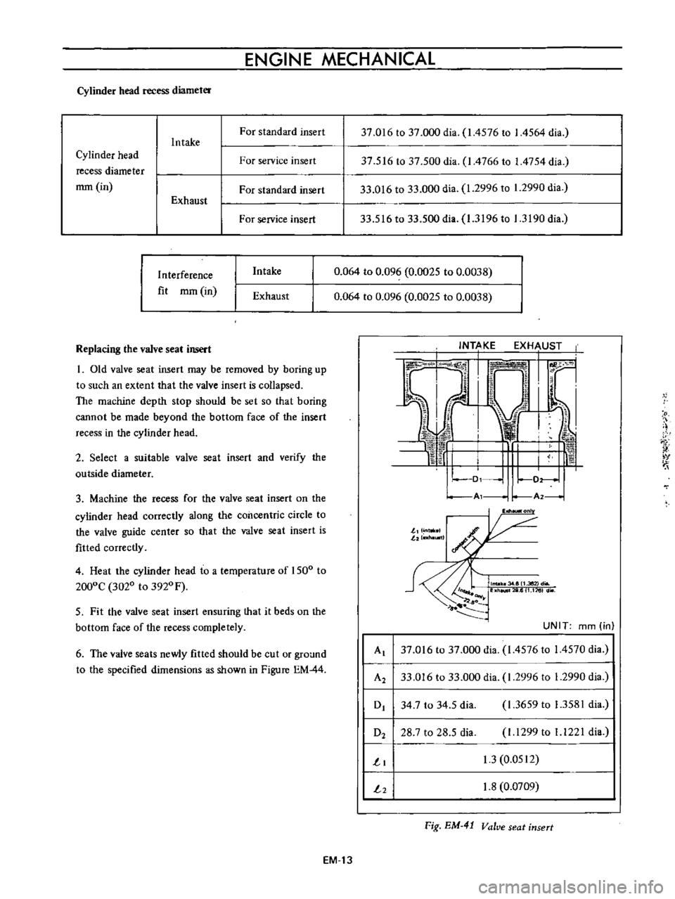
Replacing
the
valve
seat
insert
I
Old
valve
seat
insert
may
be
removed
by
boring
up
to
such
an
extent
that
the
valve
insert
is
collapsed
The
machine
depth
stop
should
be
set
so
that
boring
cannot
be
made
beyond
the
bottom
face
of
the
insert
recess
in
the
cylinder
head
2
Select
a
suitable
valve
seat
insert
and
verify
the
outside
diameter
3
Machine
the
recess
for
the
valve
seat
insert
on
the
cylinder
head
correctly
along
the
concentric
circle
to
the
valve
guide
center
so
that
the
valve
seat
insert
is
fitted
correctly
4
Heat
the
cylinder
head
to
a
temperature
of
1500
to
2000C
3020
to
3920
F
5
Fit
the
valve
seat
insert
ensuring
that
it
beds
on
the
bottom
face
of
the
recess
completely
6
The
valve
seats
newly
fitted
should
be
cut
or
ground
to
the
specified
dimensions
as
shown
in
Figure
EM
44
37
016
to
37
000
dia
1
4576
to
I
4564
dia
37
516
to
37
500
dia
I
4766
to
1
4754
dia
33
016
to
33
000
dia
1
2996
to
1
2990
dia
33
516
to
33
500
dia
1
3196
to
1
3190
dia
0
064
to
0
096
0
0025
to
0
0038
0
064
to
0
096
0
0025
to
0
0038
I
t
v
Al
r
A2
I
onl
J
J
n
llI
lltl
I
G
llW
6
UNIT
mm
in
Al
37
016
to
37
000
dia
1
4576
to
14570
dia
A2
33
016
to
33
000
dia
1
2996
to
1
2990
dia
0
34
7
to
34
5
dia
1
3659
to
1
3581
dia
O2
28
7
to
28
5
dia
I
1299
to
1
1221
dia
1
1
3
0
0512
2
1
8
0
0709
Fig
EM
41
Valve
seat
insert
EM
13