1973 DATSUN B110 Engine diagram
[x] Cancel search: Engine diagramPage 236 of 513
BODY
ELECTRICAL
WIRING
CONTENTS
WIRING
HARNESS
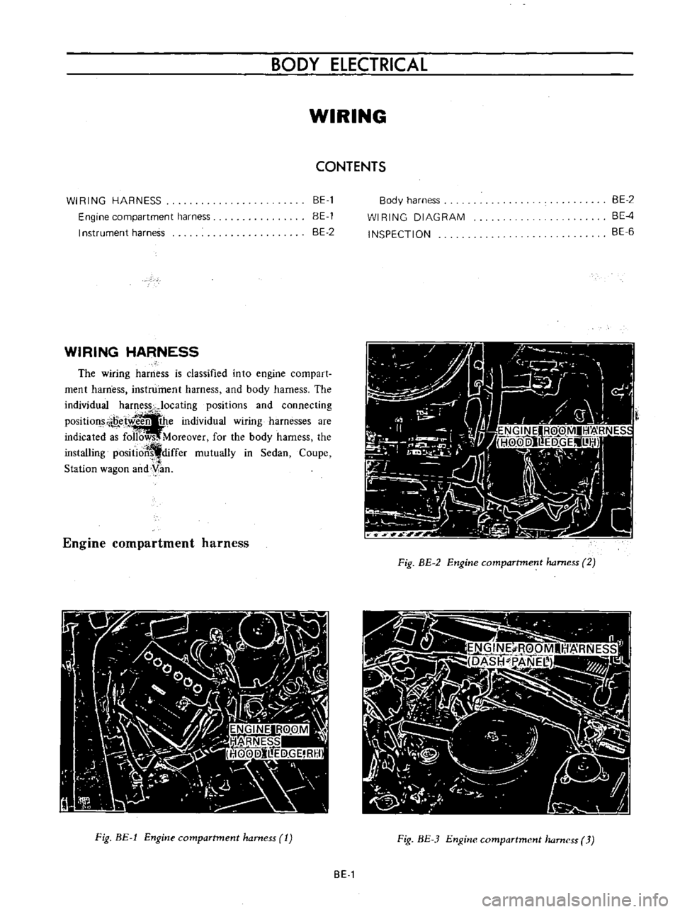
Engine
compartment
harness
I
nstrument
harness
BE
1
BE
1
BE
2
WIRING
HARNESS
The
wiring
harness
is
classified
into
engine
compart
ment
harness
instrument
harness
and
body
harness
The
individual
harness
Jocating
positions
and
connecting
Position
e
w
the
individual
wiring
harnesses
are
indicated
a
f
Moreover
for
the
body
harness
the
installing
positioJ
differ
mutually
in
Sedan
Coupe
Station
wagon
and
yan
Engine
compartment
harness
Fig
BE
1
Engine
compartment
harness
1
Body
harness
WI
RING
DIAGRAM
INSPECTION
BE
2
BE
4
BE
6
A
0
Ij
7
9
Fig
BE
2
Engine
compartment
harness
2
Fig
BE
3
Engine
compartment
harness
3
BE
1
Page 241 of 513
INSPECTION
Referring
to
the
wiring
diagram
check
the
wiring
harness
for
connection
with
electrical
equipment
and
connector
for
conned
ion
and
installation
When
checking
the
wiring
harness
note
the
following
matters
Connected
unit
should
not
be
loose
rusted
or
contaminated
2
Cable
insulator
cover
should
not
be
damaged
crack
ed
or
insulating
material
should
not
be
deteriorated
3
For
those
parts
which
are
grounded
through
the
installation
bolts
the
bolts
should
be
in
contact
with
the
body
completely
so
that
continuity
is
provided
in
between
the
body
and
bolts
4
Terminals
of
unit
through
which
current
flows
should
not
come
into
contact
with
other
metal
parts
5
No
erroneous
connection
should
be
present
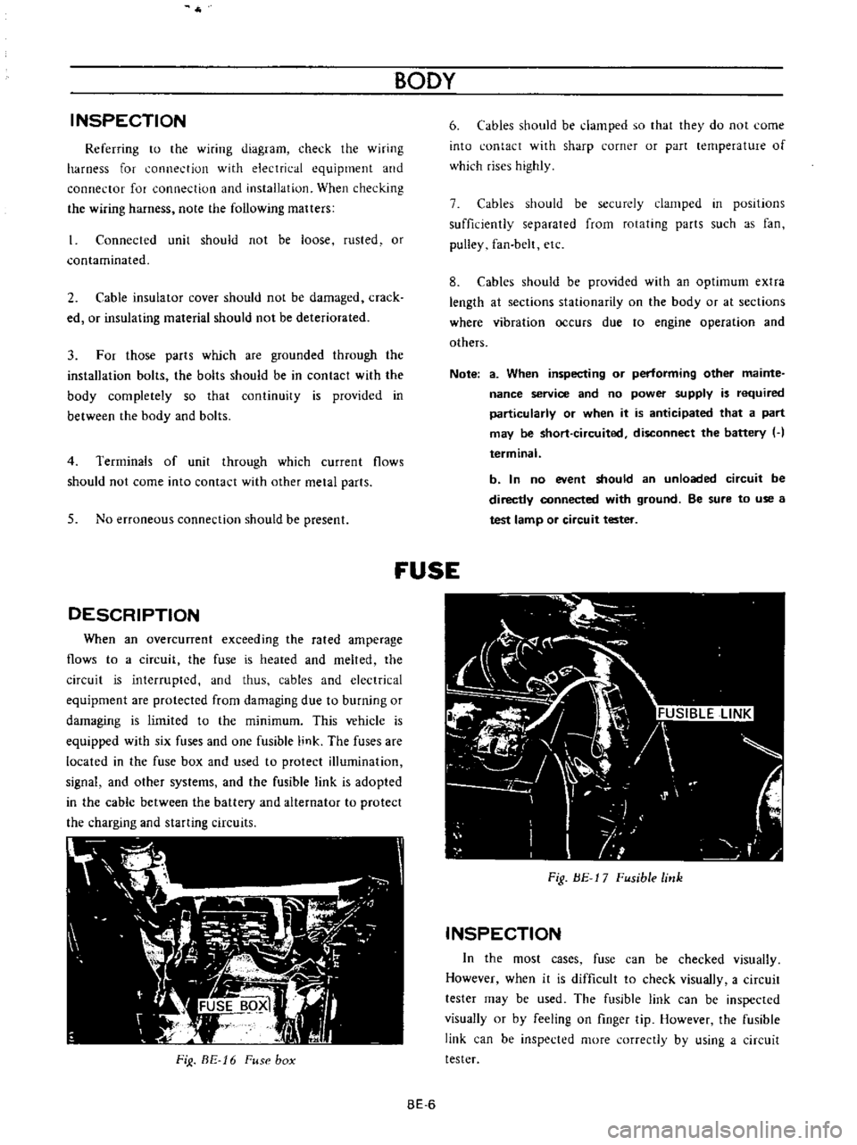
DESCRIPTION
When
an
overcunent
exceeding
the
rated
amperage
flows
to
a
circuit
the
fuse
is
heated
and
melted
the
circuit
is
interrupted
and
thus
cables
and
electrical
equipment
are
protected
from
damaging
due
to
burning
or
damaging
is
limited
to
the
minimum
This
vehicle
is
equipped
with
six
fuses
and
one
fusible
link
The
fuses
are
located
in
the
fuse
box
and
used
to
protect
illumination
signal
and
other
systems
and
the
fusible
link
is
adopted
in
the
cable
between
the
battery
and
alternator
to
protect
the
charging
and
starting
circuits
FiJ
BE
16
Fuse
box
BODY
6
Cables
should
be
damped
so
that
they
do
not
come
into
contact
with
sharp
corner
or
part
lernperature
of
which
rises
highly
7
Cables
should
be
securely
clamped
in
posItions
sufficiently
separated
from
rotating
parts
such
as
fan
pulley
fan
belt
etc
8
Cables
should
be
provided
with
an
optimum
extra
length
at
sections
stationarity
on
the
body
or
at
sections
where
vibration
occurs
due
to
engine
operation
and
others
Note
a
When
inspecting
or
performing
other
mainte
nance
service
and
no
power
supply
is
required
particularly
or
when
it
is
anticipated
that
a
part
may
be
short
circuited
disconnect
the
battery
H
terminal
b
In
no
event
should
an
unloaded
circuit
be
directly
connected
with
ground
Be
sure
to
use
a
test
lamp
or
circuit
tester
fUSE
Fig
BE
17
Fusible
link
INSPECTION
In
the
most
cases
fuse
can
be
checked
visually
However
when
it
is
difficult
to
check
visually
a
circuit
tester
may
be
used
The
fusible
link
can
be
inspected
visually
or
by
feeling
on
finger
tip
However
the
fusible
link
can
be
inspected
more
correctly
by
using
a
circuit
tester
BE
6
Page 255 of 513
BODY
REGULATOR
FUSE
M
TEMPE
RATURE
GAUGE
IGNITION
SWITCH
Lf
I
iT
Ji
1M
THERMAL
TRANSMITTER
I
J
0
I
GAUGE
TANK
UNIT
FUEL
TANK
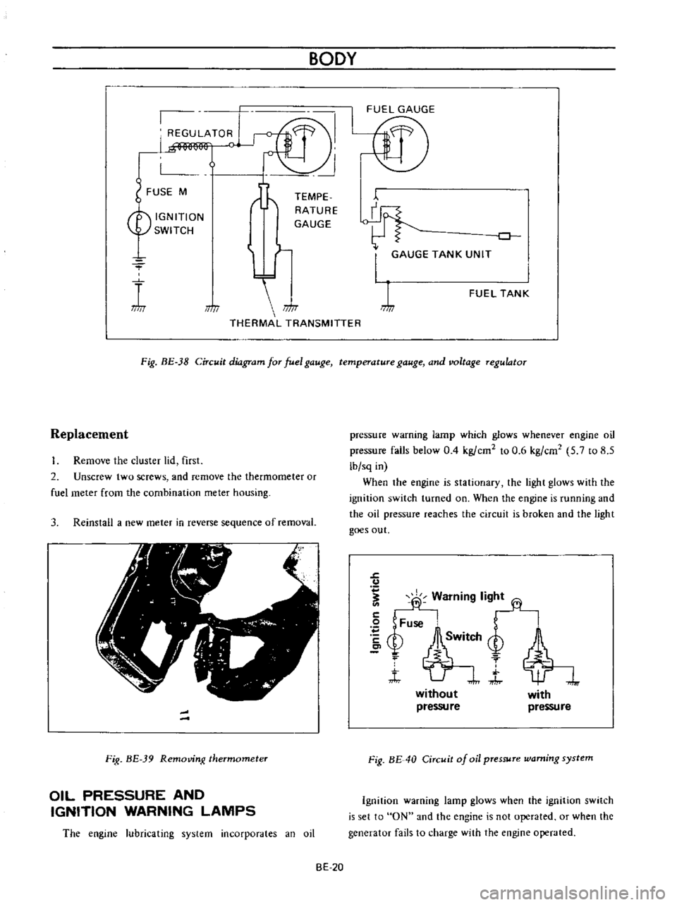
Fig
BE
38
Circuit
diagram
for
fuel
gauge
temperature
gauge
and
voltage
regulator
Replacement
Remove
the
cluster
lid
first
2
Unscrew
two
screws
and
remove
the
thermometer
or
fuel
meter
from
the
combination
meter
housing
3
Reinstall
a
new
meter
in
reverse
sequence
of
removal
Fig
BE
39
Removing
thermometer
OIL
PRESSURE
AND
IGNITION
WARNING
LAMPS
The
engine
lubricating
system
incorporates
an
oil
pressure
warning
lamp
which
glows
whenever
engine
oil
pressure
falls
below
0
4
kg
ern
to
0
6
kg
em
5
7
to
8
5
lb
sq
in
When
the
engine
is
stationary
the
light
glows
with
the
ignition
switch
turned
on
When
the
engine
is
running
and
the
oil
pressure
reaches
the
circuit
is
broken
and
the
light
goes
out
J
u
fj
Warning
lig
2
Fuse
bSM
Q
f
t
J
without
pressu
re
with
pressure
Fig
BE
40
Circuit
of
oil
pressure
warning
system
Ignition
warning
lamp
glows
when
the
ignition
switch
is
set
to
ON
and
the
engine
is
not
operated
or
when
the
generator
fails
to
charge
with
the
engine
operated
BE
20
Page 256 of 513

BODY
ElECTRICAL
When
the
ignition
switch
is
set
to
ON
the
ignition
wa
rning
circuit
is
closed
and
current
flows
flows
from
the
ignition
switch
to
the
warning
lamp
bulb
and
ground
through
the
regulator
When
the
engine
is
started
and
the
generator
comes
into
operation
the
generator
output
current
opposes
the
current
flowing
from
the
warning
lamp
in
effect
it
breaks
the
warning
circuit
ground
connection
and
the
lamp
goes
out
l
r
hffi
u
z
Ignition
switch
I
Q
6
I
0
c
M
1
E
8
ca
i
L
g
PI
lot
c
P
I
j
co
rt
0
relay
E
0
5
y
y
1
N
N
3
Alternator
Regulator
Fig
BE
41
Circuit
of
ignition
warning
system
HAND
BRAKE
WARNING
LAMP
This
lamp
functions
both
hand
brake
warning
larnp
and
BULB
SPECIFICATIONS
service
brake
line
pressure
differential
warning
lamp
When
a
difference
between
front
and
rear
brake
line
pressures
reaches
the
rated
range
13
to
17
kgfcm2
185
to
242
lb
sq
in
the
ground
circuit
for
the
warning
lamp
is
closed
and
the
warning
lamp
lights
IGNITION
SWITCH
WARNING
LAMP
L
E
WARNING
SWITCH
1
SERVICE
BRAKE
LINE
PRESSU
R
E
DIFFERENTIAL
WARNING
J
SWITCH
Fig
BE
42
Circuit
diagram
for
brake
warning
system
tern
Specifications
Square
type
meter
Round
type
meter
Meter
illumination
larnp
VoW
12
3
4
2
12
1
7
3
Turn
signal
pilot
lamp
VoW
12
3
4
2
12
1
7
2
Head
lamp
main
high
beam
VoW
12
3
4
I
12
17
1
pilot
lamp
Ignition
warning
lamp
VoW
123
4
I
12
17
1
Oil
pressure
warning
lamp
VoW
12
3
4
1
12
1
7
1
Hand
brake
warning
lamp
VoW
12
1
7
1
for
U
S
A
CANADA
Clock
illumination
lamp
VoW
123
4
I
12
17
2
Figure
encircled
in
parentheses
indicates
number
of
bulbs
used
BE
21
Page 261 of 513

The
lamp
does
not
go
out
when
the
engine
is
started
Faulty
charging
system
BODY
Inspect
the
charging
system
WINDSHIELD
WIPER
AND
WASHER
Description
Wiper
motor
replacement
Wiper
blade
operating
range
CONTENTS
BE
26
BE
27
BE
27
Description
The
windshield
wipers
consist
of
wiper
motor
link
mechanism
wiper
arms
and
blades
The
wiper
motor
unit
consists
of
a
motor
and
auto
stop
mechanism
The
wiper
rnotor
is
of
a
2
speed
type
When
the
wiper
switch
knob
is
pulled
to
the
I
st
step
the
windshield
wipers
operate
at
low
speed
and
when
pulled
to
the
2nd
step
operate
at
high
speed
The
wiper
motor
unit
is
located
on
the
cowl
dash
in
BATTERY
Cl
WIPER
MOTOR
rrQ
J
WASHER
MOTOR
IB
ILRI
L
CJ
LA
t
Y
I
Ll
j
IBI
1
f
I
LW
I
Wiper
washer
switch
replacement
Washer
nozzle
adjustment
TROUBLE
OIAGNOSES
ANO
CORRECTIONS
BE
27
BE
27
BE
28
the
engine
compartment
and
the
link
mechanism
is
located
behind
the
instrument
panel
The
electrically
operated
windshield
washer
consists
of
washing
fluid
lank
with
rnotor
and
pump
washer
nozzles
and
vinyl
tube
used
to
connect
those
compo
nents
The
windshield
washer
switch
is
combined
with
the
windshield
wiper
switch
to
a
single
unit
When
operating
the
washer
twist
the
switch
knob
IG
FUSE
W
v
l
i
f
WIPER
SWITCH
10FFI
I
2
I
TWIST
I
y
ILl
I
b
I
J
6
I
BLII
Fig
BE
43
Circuit
diagram
for
windshield
wiper
washer
system
BE
26
Page 324 of 513
EMISSION
CONTROL
AND
TUNE
UP
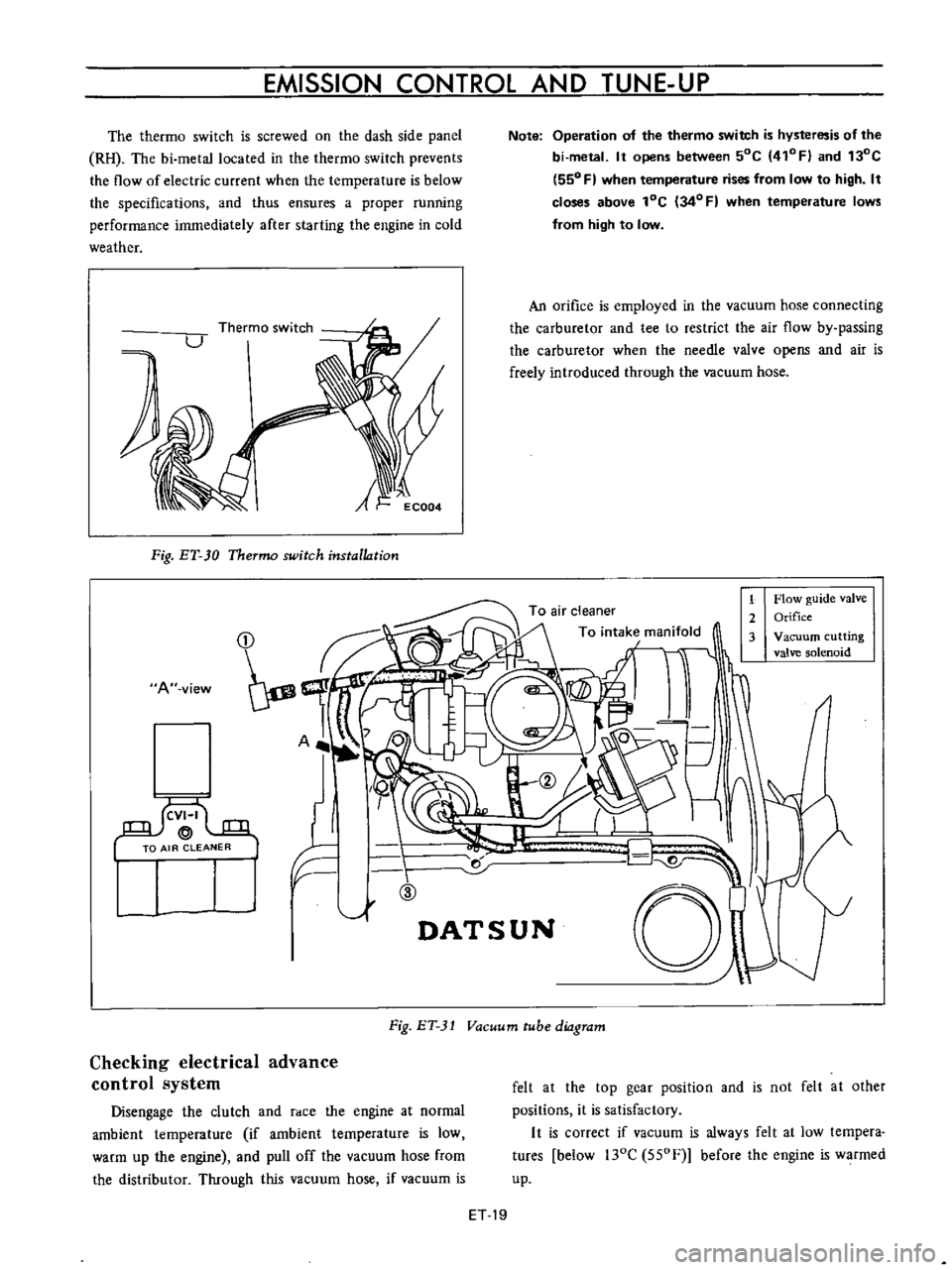
The
thermo
switch
is
screwed
on
the
dash
side
panel
RH
The
bi
metallocated
in
the
thermo
switch
prevents
the
flow
of
electric
current
when
the
temperature
is
below
the
specifications
and
thus
ensures
a
proper
running
performance
immediately
after
starting
the
engine
in
cold
weather
A
Fig
ET
30
Thermo
switch
installation
A
view
I
llf
F
ID
1
Note
Operation
of
the
thermo
switch
is
hysteresis
of
the
bi
metal
It
opens
between
50C
410FI
and
130C
550
F
when
temperature
rises
from
low
to
high
It
closes
above
lOC
34
0
F
when
temperature
lows
from
high
to
low
An
orifice
is
employed
in
the
vacuum
hose
connecting
the
carburetor
and
tee
to
restrict
the
air
flow
by
passing
the
carburetor
when
the
needle
valve
opens
and
air
is
freely
introduced
through
the
vacuum
hose
1
Flow
guide
valve
2
Orifice
3
Vacuum
cutting
valve
solenoid
r
d
01
DATSUN
Fig
ET
31
Vacuum
tube
diagram
Checking
electrical
advance
control
system
Disengage
the
clutch
and
race
the
engine
at
normal
ambient
temperature
if
ambient
temperature
is
low
warm
up
the
engine
and
pull
off
the
vacuum
hose
from
the
distributor
Through
this
vacuum
hose
if
vacuum
is
felt
at
the
top
gear
position
and
is
not
felt
at
other
positions
it
is
satisfactory
It
is
correct
if
vacuum
is
always
felt
at
low
tempera
tures
below
l30C
550F
before
the
engine
is
warmed
up
ET
19
Page 354 of 513
ENGINE
CAMSHAFT
AND
CAMSHAFT
BEARING
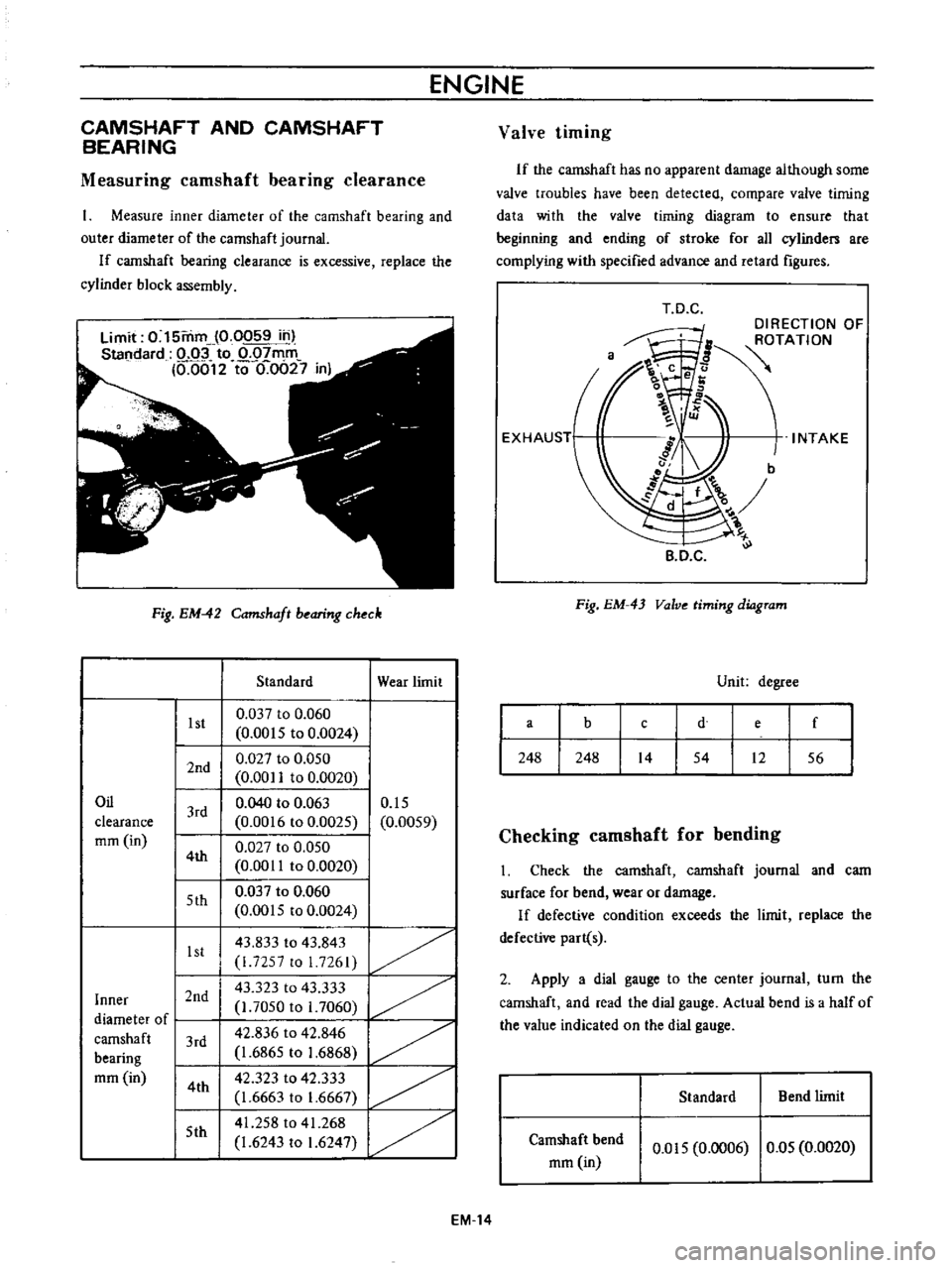
Measuring
camshaft
bearing
clearance
Measure
inner
diameter
of
the
camshaft
bearing
and
outer
diameter
of
the
camshaft
journaL
If
camshaft
bearing
clearance
is
excessive
replace
the
cylinder
block
assembly
Limit
0
15mm
0
0059
in
Standard
o
oi
to
0
07mm
M012
to
0
0627
in
Fig
EM
42
Camshaft
bearing
check
1st
2nd
Oil
clearance
mm
in
3rd
4th
5th
1st
Inner
I
2nd
I
diameter
of
I
I
camshaft
3rd
bearing
mm
in
14th
I
15th
I
Standard
0
037
to
0
060
0
0015
to
0
0024
0
027
to
0
050
0
00
to
0
0020
0
040
to
0
063
0
0016
to
0
0025
0
027
to
0
050
0
0011
to
0
0020
0
037
to
0
060
0
0015
to
0
0024
43
833
to
43
843
i
7257
to
I
7261
43
323
to
43
333
l
7050
to
1
7060
42
836
to
42
846
1
6865
to
1
6868
42
323
to
42
333
1
6663
to
1
6667
41
258
to
41
268
1
6243
to
1
6247
Wear
limit
0
15
0
0059
1
1
1
1
Valve
timing
If
the
camshaft
has
no
apparent
damage
although
some
valve
troubles
have
been
detected
compare
valve
timing
data
with
the
valve
timing
diagram
to
ensure
that
beginning
and
ending
of
stroke
for
all
cylinden
are
complying
with
specified
advance
and
retard
figures
T
D
C
DIRECTION
OF
ROTATION
INTAKE
B
D
C
Fig
EM
43
Valve
timing
diagram
Unit
degree
a
b
e
f
d
c
248
248
14
54
12
56
Checking
camshaft
for
bending
Check
the
camshaft
camshaft
journal
and
cam
surface
for
bend
wear
or
damage
If
defective
condition
exceeds
the
limit
replace
the
defective
part
s
2
Apply
a
dial
gauge
to
the
center
journal
turn
the
camshaft
and
read
the
dial
gauge
Actual
bend
is
a
half
of
the
value
indicated
on
the
dial
gauge
Standard
Bend
limit
Camshaft
bend
mm
in
0
015
0
0006
0
05
0
0020
EM
14
Page 449 of 513
ENGINE
ElECTRICAL
SYSTEM
IGNITION
CIRCUIT
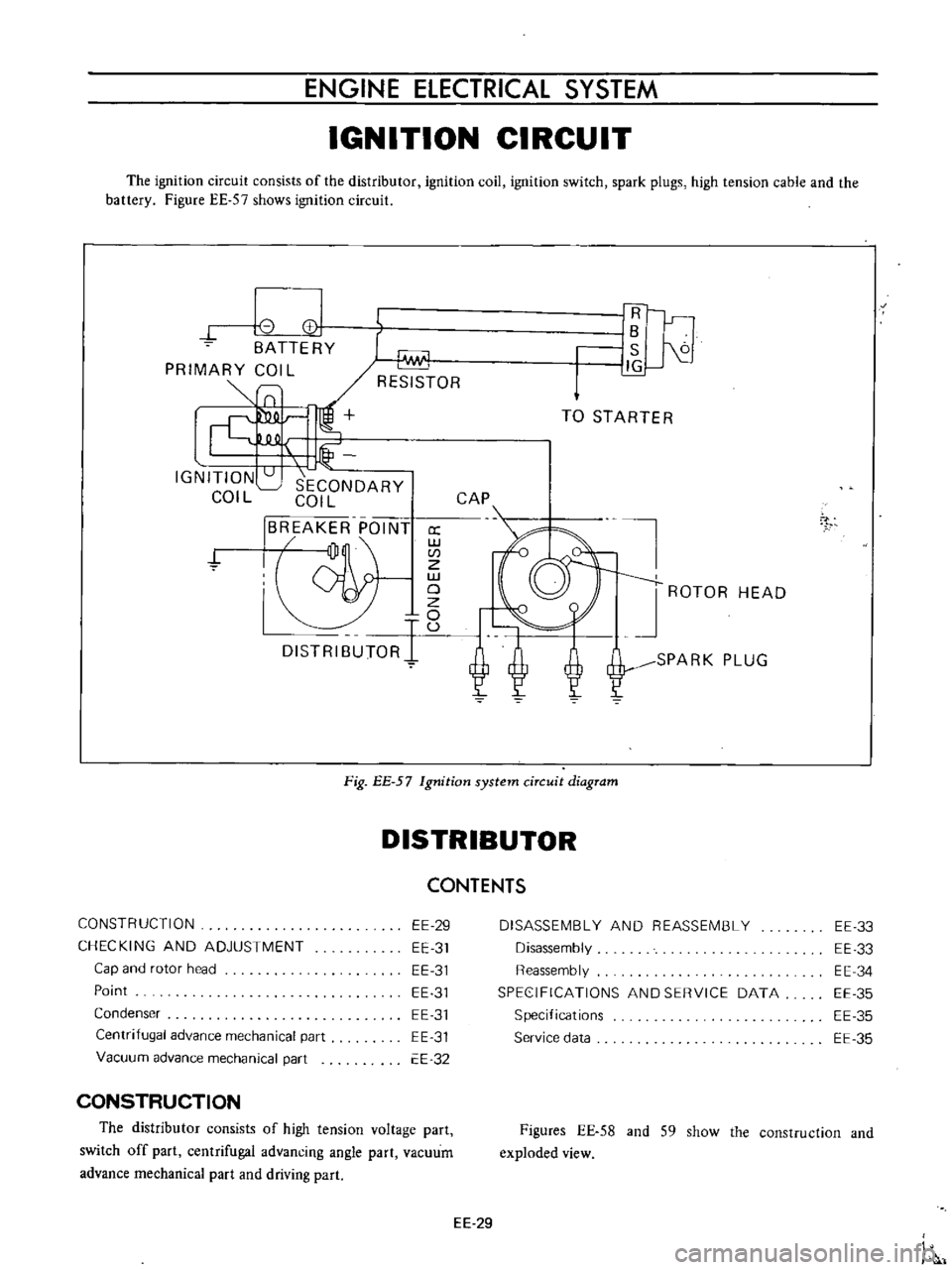
The
ignition
circuit
consists
of
the
distributor
ignition
coil
ignition
switch
spark
plugs
high
tension
cable
and
the
battery
Figure
EE
57
shows
ignition
circuit
8
I
CC
BATTERY
PRIMARY
COIL
SlO
Lf
IGNITION
SECONDARY
COIL
COIL
BREAKER
POINT
jJ
a
w
CI
Z
w
19
DISTRIBUTORI
U
1Fl
r
lB
S
J1G
TO
STARTER
CAP
ROTOR
HEAD
SPARK
PLUG
7
Fig
EE
57
Ignition
system
circuit
diagram
DISTRIBUTOR
CONSTRUCTION
CHECKING
AND
ADJUSTMENT
Cap
and
rotor
head
Point
Condenser
Centrifugal
advance
mechanical
part
Vacuum
advance
mechanical
part
EE
29
EE
31
EE
31
EE
31
EE
31
EE
31
EE
32
CONSTRUCTION
The
distributor
consists
of
high
tension
voltage
part
switch
off
part
centrifugal
advancing
angle
part
vacuum
advance
mechanical
part
and
driving
part
CONTENTS
DISASSEMBLY
AND
REASSEMBLY
Disassembly
Reassembly
SPEC
IFICATIONS
AND
SERVICE
DATA
Specifications
Service
data
EE
33
EE
33
EE
34
EE
35
EE
35
EE
35
Figures
EE
58
and
S9
show
the
construction
and
exploded
view
EE
29