1973 DATSUN B110 drain bolt
[x] Cancel search: drain boltPage 41 of 513

AUTOMATIC
TRANSMISSIO
N
i
MAJOR
REPAIR
OPERATION
SERVICE
NOTICE
FOR
DISASSEMBLY
AND
ASSEMBLY
TORQUE
CONVERTER
Inspection
TRANSMISSION
Disassembly
Inspection
Assembly
SERVICE
NOTICE
FOR
DISASSEMBLY
AND
ASSEMBLY
I
It
is
desirable
that
the
repair
operations
are
carried
out
in
the
dust
proof
room
2
Due
to
the
differences
of
the
engine
capacities
the
specifications
of
component
parts
for
each
model
s
transmission
may
be
different
How
ever
they
do
have
common
adJust
ments
and
repair
as
well
as
cleaning
and
inspection
procedures
ou
tlined
hereinafter
3
During
the
repair
operations
refer
to
the
Service
Data
and
Specifi
cations
section
for
the
correct
parts
for
the
applicable
model
transmission
4
Before
removing
any
of
subas
semblies
thoroughly
clean
the
outside
of
the
transmission
to
preven
t
dirt
from
entering
the
mechanical
parts
5
Do
not
use
a
waste
rag
Use
a
nylon
waste
or
paper
waste
6
After
disassembling
wash
all
dis
assembled
parts
clean
and
examine
them
to
see
if
there
are
any
worn
damaged
or
defective
parts
and
how
they
are
affected
Refer
to
Service
Data
for
the
extent
of
damage
that
justifies
replacement
7
Packings
seals
and
similar
parts
once
disassembled
should
be
replaced
with
new
ones
as
a
rule
TORQUE
CONVERTER
CONTENTS
AT
37
AT
37
AT
37
AT
37
AT
37
AT
39
AT
39
COMPONENT
PARTS
F
rant
clutch
Rear
clutch
Low
reverse
brake
Servo
piston
Governor
Oil
pump
Planetary
carrier
Control
valve
The
torque
converter
is
a
welded
construction
and
can
not
be
disas
sembled
Inspection
I
Check
torque
converter
for
any
sign
of
damage
bending
oil
leak
or
deformation
If
necessary
replace
2
Remove
rust
from
pilots
and
bosses
completely
If
torque
converter
oil
is
fouled
or
contaminated
due
to
burnt
clutch
flush
the
torque
converter
as
follows
I
Drain
oil
in
torque
converter
2
Pour
none
Iead
gasoline
or
kero
sene
into
torque
converter
approxi
mately
0
5
liter
I
1
8
V
S
p
7
8
Imper
p
3
Blow
air
into
torque
converter
and
flush
and
drain
out
gasoline
4
Fill
torque
converter
oil
into
torque
converter
approximately
0
5
liter
I
i
8
I
pt
7
8
lmper
pt
5
Again
blow
air
into
torque
con
verter
and
drain
torque
converter
oil
TRANSMISSION
Disassembly
I
Drain
oil
from
the
end
of
rear
extension
Mount
transmission
on
Transmission
Case
Stand
ST07860000
or
ST07870000
Remove
oil
pan
See
Figure
AT
52
AT
37
T
AT
41
AT
41
AT
42
AT
43
AT
43
AT
44
AT
44
AT
45
AT
45
2
Remove
bolts
securing
converter
housing
to
transmission
case
Remove
torque
converter
3
Remove
speedometer
pinion
sleeve
boll
Withdraw
pinion
4
Turn
off
by
hand
downshift
sole
noid
and
vacuum
diaphragm
Do
not
leave
diaphragm
rod
at
this
stage
of
disassembly
Rod
is
assembled
in
top
of
vacuum
diaphragm
See
Figure
AT
53
ST07860000
AT118
Fig
AT
52
Remouing
oil
pan
Show
2
liter
engine
model
Fig
A
T
53
Downshift
solenoid
and
uacuum
diaphragm
Page 84 of 513

PROPELLER
SHAFT
DIFFERENTIAL
CARRIER
Incorrect
adjustment
of
bearings
or
gears
Severe
service
due
to
an
excessive
loading
improper
use
of
clutch
Loosened
bolts
and
nuts
such
as
ring
gear
clamp
bolts
Oil
leakage
Worn
out
damaged
or
improperly
driven
front
oil
seal
or
bruised
dented
or
abnormally
worn
slide
face
of
companion
flange
Loosened
bolts
holding
gear
carrier
Defective
gasket
Loosen
filler
or
drain
plug
Clogged
or
damaged
breather
SERVICE
DATA
AND
SPECIFICATIONS
Type
of
differential
gear
carrier
assembly
Final
gear
type
Final
gear
ratio
number
of
teeth
Sedan
Coupe
Van
Drive
pinion
Preload
with
oil
seal
Preload
without
oil
seal
Thickness
of
drive
pinion
adjusting
shims
kg
cm
in
lb
kg
cm
in
lb
mm
in
Pinion
bearing
adjusting
spacer
Ring
gear
Backlash
between
ring
gear
and
pinion
Run
out
of
rear
side
of
ring
gear
mm
in
mm
in
Side
gear
and
pinion
mate
Thickness
of
side
gear
thrust
washers
mm
in
PD
17
Replace
defective
parts
Replace
defective
parts
Replace
defective
parts
Replace
the
defective
oil
seal
Ammend
the
affected
flange
with
sand
paper
or
replace
if
necessary
Tighten
the
bolts
to
specified
torque
Replace
defective
parts
with
new
ones
Tighten
the
plug
Repair
or
replace
H145A
Hypoid
3
900
39
10
7
to
9
6
1
to
7
8
6
to
8
5
2
to
6
9
From
2
74
to
3
25
0
1079
to
0
1280
Spacing
0
Q3
0
0012
Non
adjustable
collapsible
spacer
0
10
to
0
15
0
0039
to
0
0059
Less
than
0
05
0
0020
0
76
to
0
91
0
0299
to
0
0358
Page 127 of 513
BRAKE
TANDEM
MASTER
CYLINDER
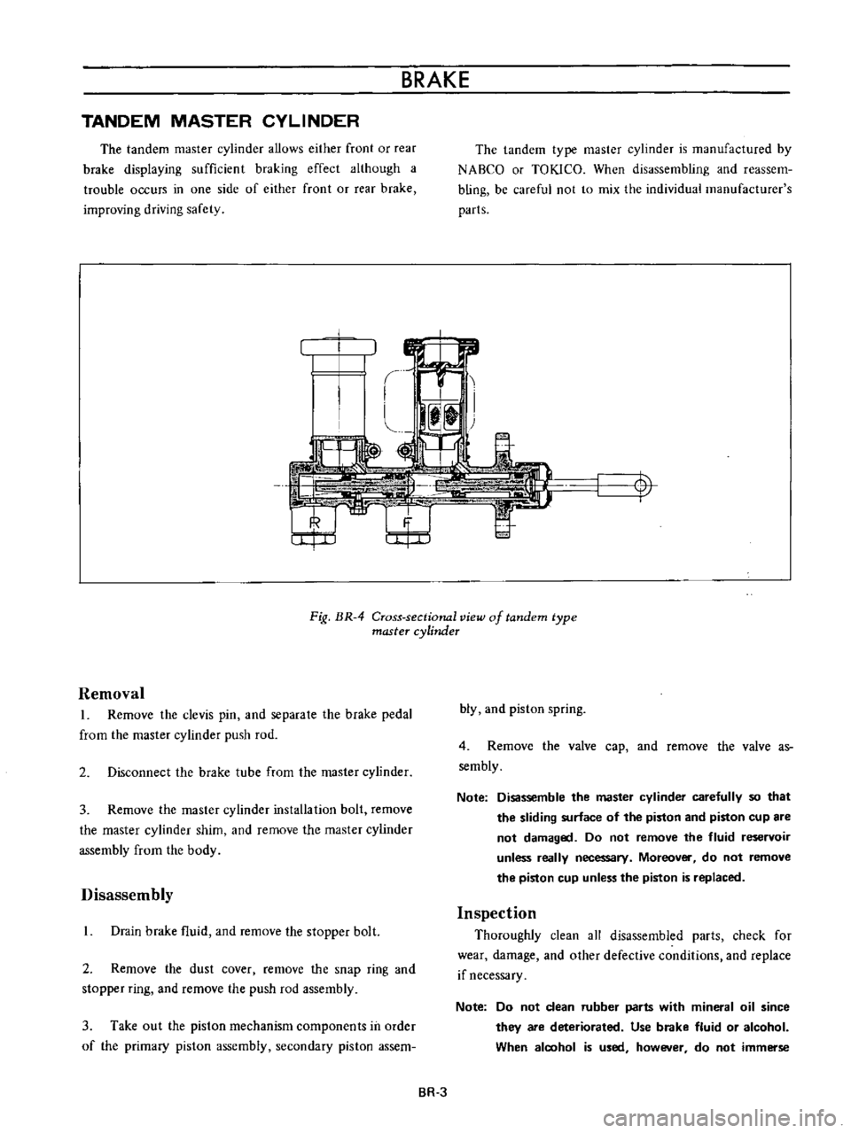
The
tandem
master
cylinder
allows
either
front
or
rear
brake
displaying
sufficient
braking
effect
although
a
trouble
occurs
in
one
side
of
either
front
or
rear
brake
improving
driving
safety
The
tandem
type
master
cylinder
is
manufactured
by
NABCO
or
TOKlCO
When
disassembling
and
reassem
bling
be
careful
not
to
mix
the
individual
manufacturer
s
parts
t
I
Fig
BR
4
Cross
sectional
view
of
tandem
type
master
cylinder
Removal
L
Remove
the
clevis
pin
and
separale
the
brake
pedal
from
the
master
cylinder
push
rod
2
Disconnect
the
brake
tube
from
the
master
cylinder
3
Remove
the
master
cylinder
installation
bolt
remove
the
master
cylinder
shim
and
remove
the
master
cylinder
assembly
from
the
body
Disassembly
L
Drain
brake
fluid
and
remove
the
stopper
bolt
2
Remove
the
dust
cover
remove
the
snap
ring
and
stopper
ring
and
remove
the
push
rod
assembly
3
Take
out
the
piston
mechanism
components
in
order
of
the
primary
piston
assembly
secondary
piston
assem
bly
and
piston
spring
4
Remove
the
valve
cap
and
remove
the
valve
as
sembly
Note
Disassemble
the
master
cylinder
carefully
so
that
the
sliding
surface
of
the
piston
and
piston
cup
are
not
damaged
Do
not
remove
the
fluid
reservoir
unless
really
necessary
Moreover
do
not
remove
the
piston
cup
unless
the
piston
is
replaced
Inspection
Thoroughly
clean
all
disassembled
parts
check
for
wear
damage
and
other
defective
conditions
and
replace
if
necessary
Note
Do
not
clean
rubber
parts
with
mineral
oil
since
they
are
deteriorated
Use
brake
fluid
or
alcohol
When
aloohol
is
used
however
do
not
immerse
BR
3
Page 137 of 513
BRAKE
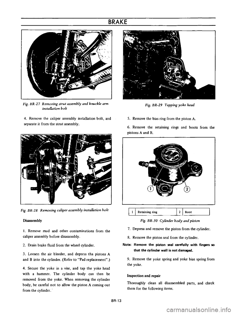
Fig
BR
27
Removing
strut
assembly
and
knuckle
arm
installation
bolt
4
Remove
the
caliper
assembly
installation
bolt
and
separate
it
from
the
strut
assembly
Fig
BR
28
Removing
caliper
assembly
instaUation
bolt
Disassembly
I
Remove
mud
and
other
contaminations
from
the
caliper
assembly
before
disassembly
2
Drain
brake
fluid
from
the
wheel
cylinder
3
Loosen
the
air
bleeder
and
depress
tha
pistons
A
and
B
into
the
cylinder
Refer
to
Pad
replacement
4
Secure
the
yoke
in
a
vise
and
tap
the
yoke
head
with
a
hammer
The
cylinder
body
can
then
be
removed
from
the
yoke
When
removing
the
cylinder
body
be
careful
not
to
allow
the
piston
A
coming
out
from
the
cylinder
BR
13
i
c
J
l
l
7
I
0
I
I
i
I
f
1
1
J
t
1
Fig
BR
29
Tapping
yoke
head
5
Remove
the
bias
ring
from
the
piston
A
6
Remove
the
retaining
rings
and
boots
from
the
pistons
A
and
B
J
l
lj
7
fI
II
l
j
B
11
I
Retaining
ring
121
Boot
Fig
BR
30
Cylinder
body
and
piston
7
Depress
and
remove
the
piston
from
the
cylinder
8
Remove
the
pislon
seal
from
the
cylinder
Note
Remove
the
piston
seal
carefully
with
fingers
so
that
the
cylinder
wall
is
not
damaged
9
Remove
the
yoke
spring
and
yoke
bias
spring
from
the
yoke
Inspection
and
repair
Thoroughly
clean
all
disassembled
parIs
and
check
them
for
the
following
items
Page 163 of 513
STEERING
6
Remove
six
bolts
used
to
secure
the
steering
column
hole
cover
to
the
dash
board
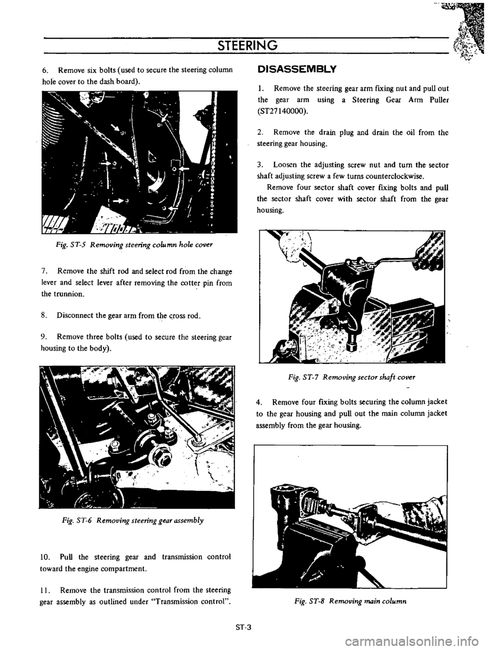
Fig
ST
5
Removing
steering
column
hole
cover
7
Remove
the
shift
rod
and
select
rod
from
the
change
lever
and
select
lever
after
removing
the
cotter
pin
from
the
trunnion
8
Disconnect
the
gear
arm
from
the
crOSS
rod
9
Remove
three
bolts
used
to
secure
the
steering
gear
housing
to
the
body
Fig
ST
6
Removing
steering
gear
assembly
10
Pull
the
steering
gear
and
transmission
control
toward
the
engine
compartment
11
Remove
the
transmission
control
from
the
steering
gear
assembly
as
outlined
under
Transmission
control
DISASSEMBLY
1
Remove
the
steering
gear
arm
fIxing
nut
and
pull
out
the
gear
arm
using
a
Steering
Gear
Arm
Puller
ST27140000
2
Remove
the
drain
plug
and
drain
the
oil
from
the
steering
gear
housing
3
Loosen
the
adjusting
screw
nut
and
turn
the
sector
shaft
adjusting
screw
a
few
turns
counterclockwise
Remove
four
sector
shaft
cover
fIxing
bolts
and
pull
the
sector
shaft
cover
with
sector
shaft
from
the
gear
housing
t
I
gJ
I
I
Fig
ST
7
Removing
sector
shaft
cover
4
Remove
four
fIxing
bolts
securing
the
column
jacket
to
the
gear
housing
and
pull
out
the
main
column
jacket
assembly
from
the
gear
housing
Fig
ST
8
Removing
main
column
ST
3
Page 184 of 513

ENGINE
CONTROL
FUEL
EXHAUST
SYSTEM
For
all
models
fuel
tank
capacity
has
been
increased
in
response
to
the
increased
engine
output
Location
and
mounting
strength
are
improved
for
improvement
of
safety
Sedan
40
l
101
2
US
gal
8
3
4
Imp
gal
Van
38
l
10
US
gal
8
3
8
Imp
gal
Coupe
38
l
10
US
gal
8
3
8
Imp
gal
and
completely
drain
fuel
2
Remove
the
fuel
line
connector
3
Remove
the
luggage
compartment
finishing
4
Remove
four
bolts
used
to
secure
the
fuel
tank
5
Loosen
the
hose
clamp
f
r
II
J
y
I
0
I
V
Ii
i
iJb
Also
for
piping
consideration
has
been
given
on
the
safety
To
be
more
specifically
the
fuel
line
coming
out
from
the
fuel
tank
is
laid
inside
the
rear
side
member
so
that
the
fuel
line
is
protected
from
gravel
and
other
interferences
from
road
In
the
front
floor
section
the
fuel
line
is
laid
inside
a
tunnel
and
thus
fuel
line
reaches
the
engine
compartment
In
addition
the
fuel
strainer
and
fuel
tank
outlet
units
connect
the
fuel
line
with
rubber
hoses
and
for
aU
other
sections
bandy
tube
is
used
Fig
FE
9
Drain
plug
position
Replacement
Remove
the
drain
plug
from
the
fuel
tank
bottom
6
Disconnect
cable
to
the
unit
gauge
7
Dismount
the
fuel
tank
f
I
Y
L
ll
C
jjhrr
@
Fig
FE
10
Fuel
tank
14nit
installation
FE
5
Page 383 of 513
LUBRICATION
CIRCUIT
Oil
drawn
from
the
oil
pan
through
the
inlet
screen
and
tube
to
the
inlet
side
of
the
oil
pump
is
delivered
by
th
oil
pump
through
the
outlet
portion
of
the
oil
pump
and
the
oil
gallery
to
the
inlet
side
of
the
full
flow
oil
filter
and
to
the
main
oil
gallery
The
main
oil
gallery
supplies
oil
to
the
crankshaft
main
bearings
and
drilled
passages
in
the
crankshaft
and
thus
oil
is
fed
directly
from
the
main
bearings
to
the
connecting
rod
bearings
Oil
injected
from
jet
holes
on
connecting
rods
lubri
cates
the
cylinder
walls
and
pistion
pins
The
oil
distributed
from
the
main
gallery
enters
the
chain
teosioner
and
the
pad
is
held
against
the
chain
by
oil
pressure
and
spring
The
oil
also
lubricates
the
timing
chain
through
the
jet
hole
located
near
the
chain
Furthermore
lubricant
is
supplied
to
each
camshaft
bearing
through
each
crankshaft
main
bearing
and
finally
to
the
011
gallery
in
the
rocker
shaft
through
the
center
camshaft
bearing
The
rocker
arm
and
valve
are
lubricated
by
the
oil
through
the
oil
gallery
in
the
rockershaft
To
this
oil
gallery
lubricant
is
supplied
through
the
center
camshaft
bearing
as
shown
in
Figure
EL
I
OIL
PUMP
Description
The
oil
pump
assembly
is
installed
on
the
bottom
of
the
cylinder
block
and
driven
by
the
distributor
drive
shaft
assembly
The
oil
pump
is
of
a
rotor
type
The
oil
pressure
is
regulated
by
the
regulator
valve
camshaft
Removal
Engine
in
vehicle
Drain
engine
oil
2
Remove
the
frunt
stabilizer
3
Remove
the
splash
shield
board
4
Detach
the
oil
pump
body
together
with
drive
gear
spindle
ENGINE
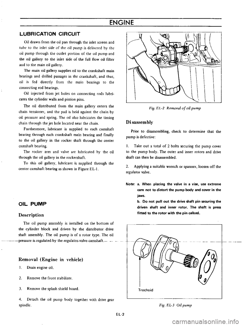
Fig
EL
2
Removal
of
oil
pump
Disassembly
Prior
to
disassembling
check
to
determine
that
the
pump
is
defective
Take
out
a
total
of
2
bolts
securing
the
pump
cover
to
the
pump
body
The
outer
and
inner
rotors
and
drive
shaft
can
then
be
disassembled
2
Applying
a
suitable
wrench
or
spanner
loosen
off
the
regulator
valve
Note
a
When
placing
the
valve
in
a
vise
use
extreme
care
not
to
distort
the
pump
body
and
cover
in
the
jaws
b
Do
not
pull
out
the
drive
shaft
pin
securing
the
driven
shaft
and
inner
rotor
The
shaft
is
press
fitted
to
the
rotor
with
the
pin
calked
n
Trochoid
Fig
EL
Oil
pump
EL
2
Page 389 of 513
COOLING
SYSTEM
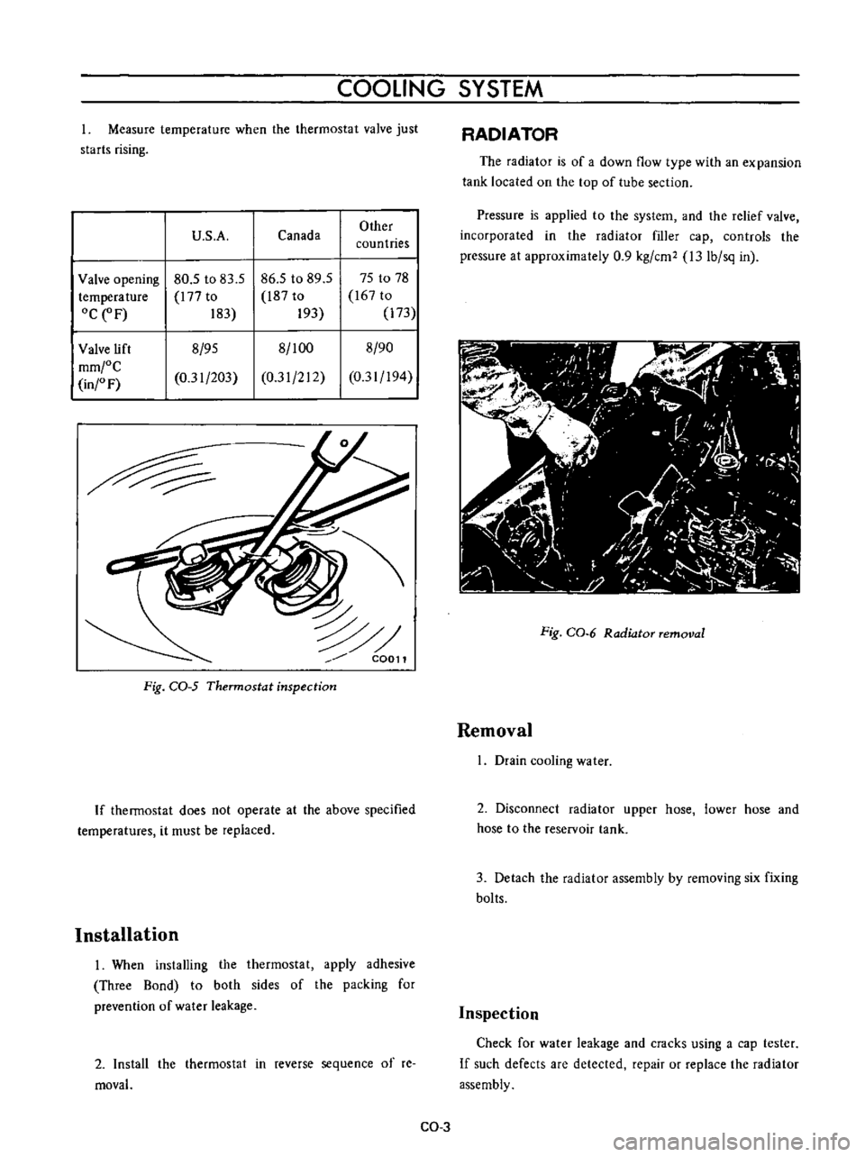
Measure
temperature
when
the
thermostat
valve
just
starts
rising
U
S
A
Canada
Other
countries
Valve
opening
80
5
to
83
5
86
5
to
89
5
75
to
78
temperature
l77
to
l87
to
167
to
OCeF
183
193
173
Valve
lift
8
95
8
100
8
90
mm
C
0
31
203
0
31
212
0
31
194
in
F
C0011
Fig
CQ
5
Thermostat
inspection
If
thermostat
does
not
operate
at
the
above
specified
temperatures
it
must
be
replaced
Installation
I
When
installing
the
thermostat
apply
adhesive
Three
Bond
to
both
sides
of
the
packing
for
prevention
of
water
leakage
2
Install
the
thermostat
in
reverse
sequence
of
re
moval
RADIATOR
The
radiator
is
of
a
down
flow
type
with
an
expansion
tank
located
on
the
top
of
tube
section
Pressure
is
applied
to
the
system
and
the
relief
valve
incorporated
in
the
radiator
filler
cap
controls
the
pressure
at
approximately
0
9
kg
cm2
l3
Ib
sq
in
Fig
CO
6
Radiator
removal
Removal
I
Drain
cooling
water
2
Disconnect
radiator
upper
hose
lower
hose
and
hose
to
the
reservoir
tank
3
Detach
the
radiator
assembly
by
removing
six
fixing
bolts
Inspection
Check
for
water
leakage
and
cracks
using
a
cap
tester
If
such
defects
are
detected
repair
or
replace
the
radiator
assembly
CO
3