1973 DATSUN B110 clock
[x] Cancel search: clockPage 20 of 513

R
range
Reverse
In
R
range
the
front
clutch
and
low
and
reverse
brake
are
applied
The
power
flow
is
through
the
input
shaft
front
clutch
connecting
sheU
and
to
the
sun
gear
Clockwise
rotatiun
of
the
sun
gear
causes
counterclockwise
rotation
of
the
rear
planetary
gears
With
the
connecting
drum
held
sta
tionary
by
the
low
and
reverse
brake
the
rear
planetary
gears
rotate
the
rear
internal
gear
and
drive
flange
counter
clockwise
The
rear
drive
flange
splined
to
the
output
shaft
rotates
the
output
shaft
counterclockwise
at
a
reduced
speed
with
an
increase
in
torque
for
reverse
gear
J
When
the
manual
valve
V
is
posi
tioned
at
R
range
the
oil
having
the
line
pressure
7
is
directed
to
the
line
pressure
circuits
5
and
6
The
pressure
in
the
circuit
ID
actuates
the
low
and
reverse
brake
after
being
introduced
into
the
line
pressure
cir
cuit
I2
through
the
lst
2nd
shift
valve
ID
The
pressure
in
the
circuit
operates
the
release
side
ofband
servo
and
the
front
clutch
after
being
led
to
the
line
pressure
circuit
10
through
the
2nd
3rd
shift
valve
@
The
throttle
pressure
16
and
the
line
pressure
6
which
vary
with
the
degree
of
the
depression
of
accelerator
pedal
both
act
on
the
pressure
regula
tor
valve
CD
and
press
its
valve
CD
increasing
the
line
pressure
7
In
R
range
the
governor
pressure
is
absent
making
all
sllch
valves
inoperative
as
the
lst
2nd
shift
valve
@
2nd
3rd
shift
valve
and
pressure
modifier
valve
@
CHASSIS
R
C
Fig
AT
26
Power
transmission
during
R
range
lI
a
Go
I
w
L
AT085
Fig
AT
27
Operation
of
each
mechani6m
duirng
OR
range
Clutch
low
Band
servo
One
Parking
Ran
Gear
ratio
reverse
way
pawl
Front
Rear
brake
Operation
Release
clutch
Park
on
on
Reverse
2
182
on
on
on
Neutral
01
low
2
458
nn
on
Drive
D2
Second
458
nn
on
OJ
Top
1
000
on
on
2
Second
458
nn
t2
Second
458
on
tt
low
2
458
on
on
AT
16
Page 24 of 513

CHASSIS
D
range
Low
gear
The
low
gear
in
D
range
is
somewhat
different
from
that
in
II
range
The
rear
clutch
is
applied
as
in
range
but
the
une
way
duldl
is
holding
the
connecling
drum
The
power
flow
is
the
same
as
in
11
range
That
is
the
power
flow
takes
place
through
Ihe
input
shaft
and
into
the
rear
clutch
The
input
shaft
is
splined
to
the
rear
clutch
drum
and
drives
it
Rotation
of
the
rear
clutch
dri
es
the
rear
clutch
hub
and
from
internal
gear
The
front
inlernal
gear
rotates
the
front
planetary
gears
clockwise
to
cause
the
sun
gear
to
rotate
counter
clockwise
Counterclockwise
rotation
of
the
sun
gear
turns
the
rear
planetary
gears
clockwise
With
the
Tear
plane
tary
carrier
held
stationary
by
the
one
way
clutch
the
clockwise
rotation
of
the
rear
planetary
gears
rotates
the
rear
internal
gear
and
drives
flange
clockwise
The
internal
drive
flange
is
splined
to
the
output
shaft
and
rotates
the
output
shaft
clockwise
When
the
manual
valve
is
posi
tioned
at
D
the
line
pressure
7
introduced
into
the
manual
valve
is
led
to
the
line
pressure
circuits
I
2
and
3
The
pressure
in
the
circuit
I
actuates
the
rear
clutch
and
the
gover
nor
and
at
the
same
time
operates
the
lst
2no
shift
valve
ID
to
change
the
speed
The
circuit
2
leads
to
the
second
lock
valve
@
The
circuit
3
actuales
the
2nd
3rd
shift
valve
0
for
the
2nd
3rd
speed
change
and
at
the
same
time
locks
the
second
lock
valve
@
The
throllIe
pressure
16
which
changes
with
the
degree
of
accelerator
pedal
depression
presses
the
pressure
regulator
valve
CD
and
increases
the
line
pressure
7
When
Ihe
speed
of
vehicle
has
increased
the
governor
pressure
J
5
inlroduced
from
the
line
pressure
circuit
ll
actuates
the
lst
2nd
shift
valve
ID
2nd
3rd
shift
valve
@
and
pressure
modifier
valve
@
When
the
governor
pressure
is
high
the
pressure
modifier
valve
CID
acts
in
such
a
direction
as
to
compress
C
AT080
Fig
A
T
30
Power
transmission
during
V
range
ATOP1
dmifi
Fig
AT
3
Operation
of
each
mechanism
during
VI
range
G
Clutch
Low
Band
rVo
One
Parking
Ro
reverse
woy
pawl
ratio
Front
Rear
brake
Operation
Release
clutch
Park
on
on
Reverse
2
182
on
on
on
Neutral
01
low
14
8
on
on
Drive
01
Second
1
458
on
on
03
Top
1
000
on
on
on
on
1
Second
1
458
on
on
tl
Second
1
458
on
on
1
II
low
2
458
on
on
rhe
spring
and
the
throttle
pressure
is
led
10
the
throllIe
pressure
18
This
pressure
acts
againsr
the
force
of
spring
of
the
pressure
regulator
valve
CD
and
also
against
the
Ihrollle
pres
sure
16
thus
lowering
the
line
pres
sure
7
The
governor
pressure
also
increases
with
the
speed
of
vehicle
exerting
a
pressure
on
one
side
of
the
1st
2nd
shift
valve
and
counteracts
the
throt
lie
p
ssure
19
line
pressure
I
and
the
spring
which
are
exerting
against
the
governor
pressure
Therefore
when
the
governor
pressure
exceeds
this
pressure
the
speed
is
shifted
from
Ihe
I
Sl
gear
10
the
2nd
gear
The
further
the
acceleraror
pedal
is
de
pressed
the
higher
becomes
the
throt
tle
pressure
19
increasing
the
gover
nor
pressure
and
shifting
the
speed
change
point
to
the
higher
side
AT
20
Page 26 of 513
CHASSIS
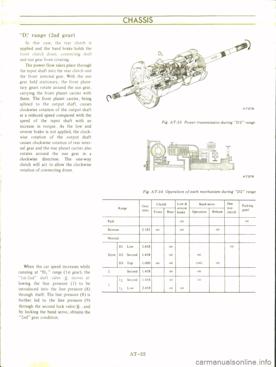
D
range
2nd
gl
ar
In
this
case
the
rear
dutch
is
applied
and
the
band
brake
holds
the
front
dUh
h
drum
i
onnel
ting
shell
and
sun
gear
from
rotating
The
power
now
takes
place
through
the
input
shaft
into
the
rear
dutch
and
the
front
internal
gear
WHh
the
sun
gear
held
stationary
the
fronr
plane
lacy
gears
rotate
around
the
sun
gear
carrying
the
front
planet
carrier
with
them
The
front
planet
carrier
being
splined
to
the
output
shaft
causes
clockwise
rotation
of
the
output
shafr
at
a
reduced
speed
compared
with
the
speed
of
the
input
shaft
with
an
increase
in
torque
As
the
low
and
reverse
brake
is
not
applied
the
clock
wise
rotation
of
the
output
shaft
causes
clockwise
rotation
of
rear
inter
nal
gear
and
the
rear
planet
carrier
also
rotates
around
the
sun
gear
in
a
clockwise
direction
The
one
way
clutch
will
act
to
allow
the
clockwise
rotation
of
connecting
drum
When
the
car
speed
increases
while
running
at
D
range
1st
gear
the
st
2nd
shift
valve
4
moves
al
lowing
the
line
pressure
I
to
be
introduced
into
the
line
pressure
8
through
itself
The
line
pressure
8
is
further
led
to
the
line
pressure
9
through
the
second
lock
vaIve@
and
by
locking
the
band
servo
obtains
the
2nd
gear
condition
Fig
A
T
33
Power
transmission
during
D2
range
I
r
J
ITMi
A
T079
Fig
A
T
34
Operation
of
each
mechanism
during
D2
range
C
w
Clutch
low
Band
selva
On
Parking
Range
ratio
reverse
w
y
pawl
Front
Rear
brake
Operation
Rdea5e
clutch
Park
on
on
Reverse
2
182
on
on
on
Ne
ulral
01
low
2
458
on
on
Drive
01
Second
1
458
on
on
OJ
Top
000
on
on
on
on
1
Se
cond
458
on
on
11
Second
1
458
on
on
low
1
458
on
on
AT
22
Page 32 of 513
CHASSIS
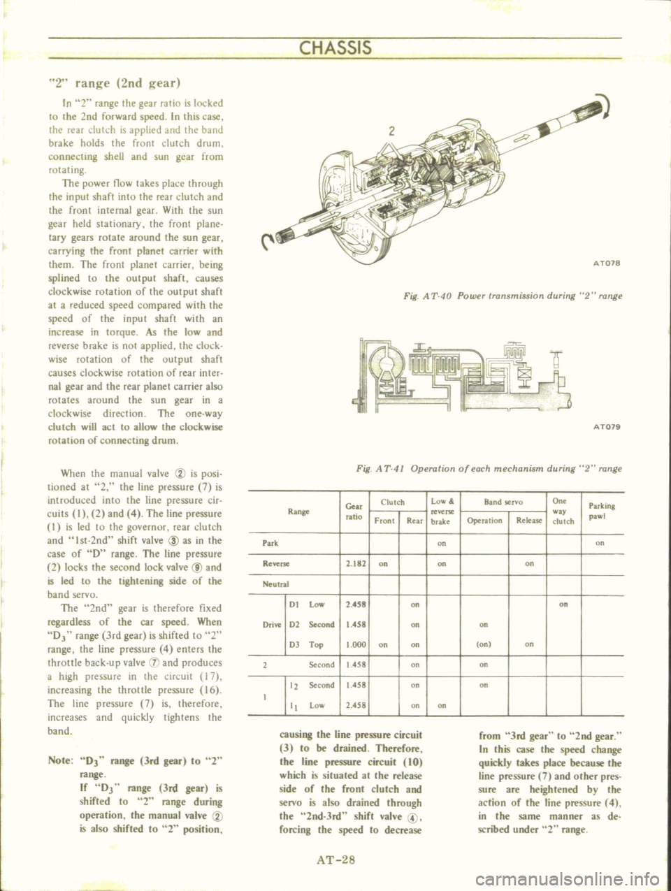
2
range
2nd
gear
In
2
range
the
gear
ratio
is
locked
to
the
2nd
forward
speed
In
this
case
the
rear
clutch
is
applied
and
the
band
brake
holds
the
front
clutch
drum
connecting
shell
and
sun
gear
from
rotating
The
power
flow
takes
place
through
the
input
shaft
into
the
rear
clutch
and
the
front
internal
gear
With
the
sun
gear
held
stationary
the
front
plane
lacy
gears
rotate
around
the
sun
gear
carrying
the
front
planet
carrier
with
them
The
front
planet
carrier
being
splined
to
the
output
shaft
causes
clockwise
rotation
of
the
output
shaft
at
a
reduced
speed
compared
with
the
speed
of
the
input
shaft
with
an
increase
in
torque
As
the
low
and
reverse
brake
is
not
applied
the
clock
wise
mlation
of
the
output
shaft
causes
clockwise
rotation
of
rear
inter
nal
gear
and
the
rear
planet
carrier
also
rotates
around
the
sun
gear
in
a
clockwise
direction
The
one
way
c1urch
will
act
to
allow
the
clockwise
rotation
of
connecting
drum
When
the
manual
valve
CV
is
posi
tioned
at
2
the
line
pressure
7
is
introduced
into
the
line
pressure
cir
cuits
I
2
and
4
The
line
pressure
I
is
led
to
the
governur
rear
dutch
and
Ist
2nd
shift
valve
ID
as
in
the
case
of
D
range
The
line
pressure
2
locks
the
second
lock
valve
@
and
is
led
to
the
tightening
side
of
the
band
servo
The
2nd
gear
is
therefore
fixed
regardless
of
the
car
speed
When
DJ
range
3rd
gear
is
shifted
to
2
range
the
line
pressure
4
enters
the
throttle
back
up
valve
IJ
and
produces
a
high
pressure
in
the
circuit
17
increasing
the
throttle
pressure
16
The
line
pressure
7
is
therefore
increases
and
quickly
tightens
the
band
Note
DJ
range
3rd
gear
to
2
range
If
DJ
range
3rd
gear
is
shifted
to
2
range
during
operation
the
manual
valve
CV
is
also
shifted
to
2
position
Fig
A
T
40
Powu
transmission
during
2
range
f
IY
9
3
AT079
Fig
A
T
41
Operation
of
each
mechanism
during
2
range
Gear
Clutch
low
Band
servo
On
Parking
Range
ratio
w
pawl
Front
Rear
brake
Operation
Relea
se
clutch
Park
on
on
Reverse
2
182
on
on
on
Neutral
I
t
Low
2
4S8
on
on
Drive
1
2
Second
1
458
on
on
1
Top
t
OOO
on
on
on
on
2
Second
1
458
on
on
12
Second
1
458
on
on
t
tt
Low
2
458
on
on
causing
the
line
pressure
circuit
3
to
be
drained
Therefore
the
line
pressure
circuit
10
which
is
situated
at
the
release
side
of
the
front
clutch
and
senro
is
also
drained
through
the
2nd
3rd
shift
valve
@
forcing
the
speed
to
decrease
from
3rd
gear
to
2nd
gear
In
this
case
the
speed
change
quickly
takes
place
because
the
line
pressure
7
and
other
pres
sure
are
heightened
by
the
action
of
the
line
pressure
4
in
the
same
manner
as
de
scribed
under
2
range
AT
28
Page 34 of 513
CHASSIS
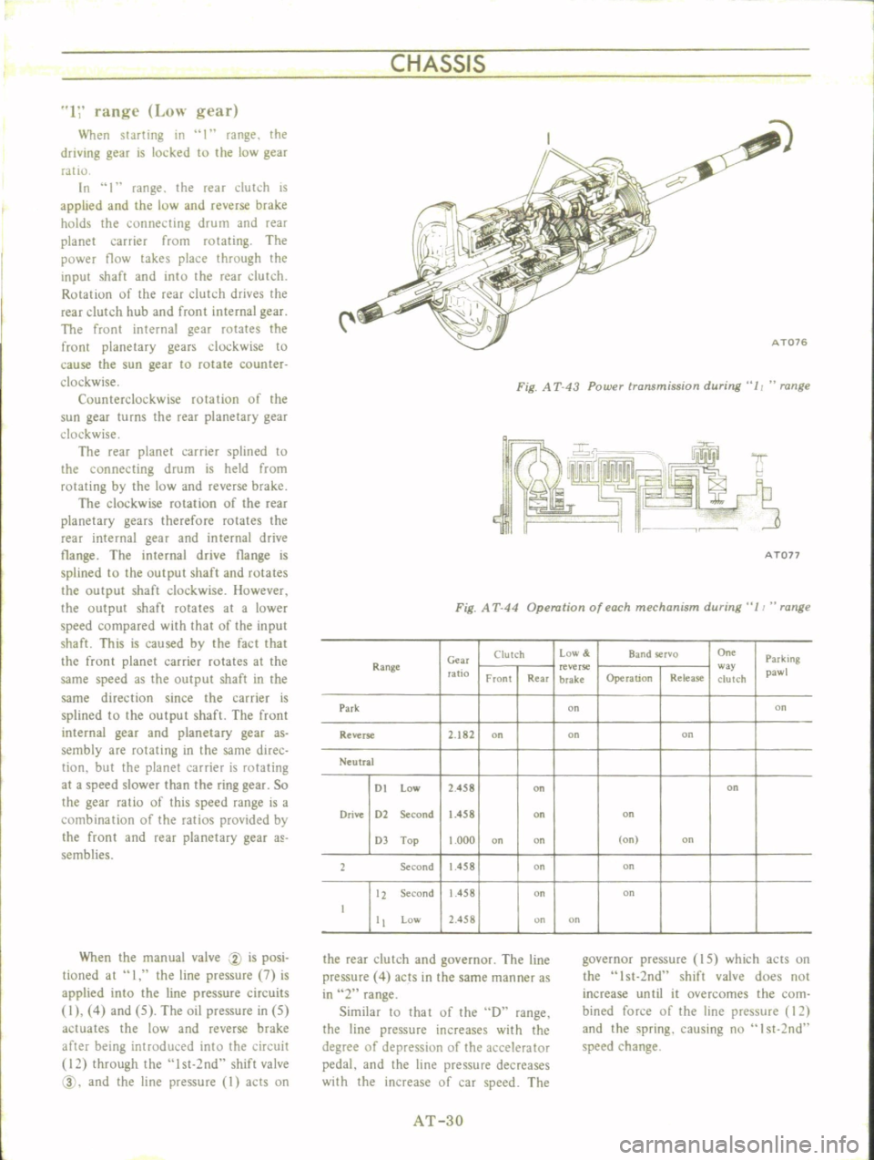
1
range
Low
gear
When
starting
in
I
range
the
driving
gear
is
locked
to
the
low
gear
ratIO
In
1
range
the
reaT
dutch
is
applied
and
the
low
and
reverse
brake
holds
the
connecting
drum
and
rear
planet
carrier
from
rotating
The
power
flow
takes
place
through
the
input
shaft
and
into
the
rear
dutch
Rotation
of
the
rear
clutch
drives
the
rear
clutch
hub
and
front
internal
gear
The
front
internal
gear
rotates
the
front
planetary
gears
clockwise
to
cause
the
sun
gear
to
rotate
counter
clockwise
Counterclockwise
rotation
of
the
sun
gear
turns
the
rear
planetary
gear
clockwise
The
rear
planet
carrier
splined
to
the
connecting
drum
is
held
from
rotating
by
the
low
and
reverse
brake
The
clockwise
rotation
of
the
rear
planetary
gears
therefore
rotates
the
rear
internal
gear
and
internal
drive
tlange
The
internal
drive
tlange
is
splined
to
the
output
shaft
and
rotates
the
output
shaft
clockwise
However
the
output
shaft
rotates
at
a
lower
speed
compared
with
that
of
the
input
shaft
This
is
caused
by
the
fact
that
the
front
planet
carrier
rotates
at
the
same
speed
as
the
output
shaft
in
the
same
direction
since
the
carrier
is
splined
to
the
output
shaft
The
front
internal
gear
and
planetary
gear
as
sembly
are
rotating
in
the
same
direc
tion
but
the
planet
carrier
is
rotating
at
a
speed
slower
than
the
ring
gear
So
the
gear
ratio
of
this
speed
range
is
a
combination
of
the
ratios
provided
by
the
front
and
rear
planetary
gear
a
semblies
When
the
manual
valve
CV
is
posi
tioned
at
I
the
line
pressure
7
is
applied
into
the
line
pressure
circuits
I
4
and
5
The
oil
pressure
in
5
actuates
the
low
and
reverse
brake
after
being
introduced
into
the
circuit
12
through
the
lst
2nd
shift
valve
@
and
the
line
pressure
I
acts
on
i
C
AT076
Fig
A
T
43
Power
transmission
during
11
range
A
Ton
Fig
A
T
44
Operation
of
each
mechanism
during
11
range
Clutch
Low
Band
rvo
On
Parking
Range
Gm
ratio
reverse
w
pawl
Front
Rear
brake
Operation
Release
clutch
Park
on
on
Reverse
2
182
on
on
on
Neutral
DI
low
2
458
on
on
Drive
D2
Second
1
458
on
on
D
Top
1
000
on
on
on
on
2
Second
1
458
on
on
12
Second
1
458
on
on
I
Low
2
458
on
on
the
rear
clutch
and
governor
The
line
pressure
4
acts
in
the
same
manner
as
in
2
range
Similar
10
that
of
the
D
range
the
line
pressure
increases
with
the
degree
of
depressiun
of
the
accelerator
pedal
and
the
line
pressure
decreases
with
the
increase
of
car
speed
The
governor
pressure
IS
which
acts
on
the
Ist
2nd
shift
valve
does
not
increase
until
it
overcomes
the
com
bined
force
of
the
line
pressure
12
and
the
spring
causing
nu
I
st
2nd
speed
change
AT
3D
Page 44 of 513
Low
and
reverse
brake
clearance
0
8
to
1
05
mm
0
031
to
0
041
in
Fig
AT
70
Measuring
ring
to
plate
clearanc
Available
retaining
plate
No
Thickness
mm
in
I
15
8
0
622
2
16
0
0
630
3
16
2
0
638
4
16
4
0
646
5
16
6
0
654
6
16
8
0
661
As
to
inspection
procedure
for
low
and
reverse
brake
see
page
AT
43
3
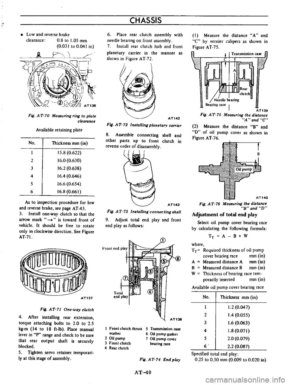
Install
one
way
clutch
so
that
the
arrow
mark
is
toward
front
of
vehicle
It
should
be
free
to
rotate
only
in
clockwise
direction
See
Figure
AT71
AT131
Fig
AT
71
One
way
clutch
4
After
installing
rear
extension
torque
attaching
bolts
to
2
0
to
2
5
kg
m
14
to
18
ft
lb
Place
manual
lever
in
P
range
and
check
to
be
sure
that
rear
output
shaft
is
securely
blocked
5
Tighten
servo
retainer
temporari
Iy
at
this
stage
of
assembly
CHASSIS
6
Place
rear
clutch
assembly
with
needle
bearing
on
front
assembly
7
Install
rear
clutch
hub
and
front
planetary
carrier
in
the
manner
as
shown
in
Figure
AT
72
AT142
Fig
AT
72
Installing
planetary
carrier
8
Assemble
connecting
shell
and
other
parts
up
to
front
clutch
in
reve
e
order
of
disassembly
ATl43
Fig
AT
73
In
talling
connecting
hell
9
Adjust
total
end
play
and
front
end
playas
follows
L
@
8
S
I
fT
15
l
r
1
Front
clutch
thrust
washer
2
Oil
pump
3
Front
clutch
4
Rear
du
tch
S
Transmission
case
6
Oil
pump
gasket
7
Oil
pump
cover
bearing
race
Fig
AT
74
Endplay
AT
40
I
Measure
the
distance
A
and
e
by
vernier
calipers
as
shown
in
Figure
AT
75
fl
l
I
Transmission
case
1l
Lf
ar
n
h
AT139
Fig
AT
75
Measuring
the
diltance
A
and
C
2
Measure
the
distance
B
and
D
of
oil
pump
COVer
as
shown
in
Figure
AT
76
B
AT140
Fig
AT
76
MeaJIuring
the
diltanc
B
and
D
Adjustment
of
total
end
play
Select
oil
pump
cover
bearing
race
by
calculating
the
following
formula
TT
A
B
W
where
TT
Required
thickness
of
oil
pump
cover
bearing
race
mm
in
A
Measured
distance
A
mm
in
B
Measured
distance
B
mm
in
W
Thickness
of
bearing
race
tem
porarily
inserted
mm
in
Available
oil
pump
cover
bearing
race
No
Thickness
mm
in
I
1
2
0
04
7
2
I
4
0
055
3
1
6
0
063
4
1
8
0
071
5
2
0
0
079
6
2
2
0
087
Specified
total
end
play
0
25
to
0
50
mm
0
009
to
0
020
in
Page 96 of 513
CHASSIS
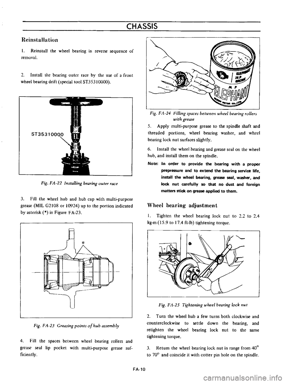
Reinstallation
Reinstall
the
wheel
bearing
in
reverse
sequence
of
removal
2
Install
the
bearing
outer
race
by
the
use
of
a
froot
wheel
bearing
drift
special
tool
ST353
10000
Fig
FA
22
Installing
bearing
outer
race
3
Fill
the
wheel
hub
and
hub
cap
with
multi
purpose
grease
MIL
G2108
or
10924
up
to
the
portion
indicated
by
asterisk
in
Figure
F
A
23
l
I
L
I
I
P
p
r
Fig
FA
23
Greasing
points
of
hub
assembly
4
Fill
the
spaces
between
wheel
bearing
rollers
and
grease
seal
lip
pocket
with
multi
purpose
grease
suf
ficiently
FA
10
Fig
FA
24
Filling
spaces
betweetJ
wheel
bearing
rollers
with
grease
5
Apply
multi
purpose
grease
to
the
spindle
shaft
and
threaded
portions
wheel
bearing
washer
and
wheel
bearing
lock
nut
surfaces
slightly
6
Install
the
wheei
bearing
and
grease
seal
on
the
wheel
hub
and
install
them
on
the
spindle
Note
In
order
to
provide
the
bearing
with
a
proper
prepressure
and
to
extend
the
bearing
service
life
install
the
wheel
bearing
grease
seal
washer
and
lock
nut
carefully
so
that
no
dust
and
foreign
matters
stick
on
grease
applied
to
them
Wheel
bearing
adjustment
I
Tighten
the
wheel
bearing
lock
nut
to
2
2
to
2
4
kg
m
15
9
to
174
ft
lb
tightening
torque
Fig
FA
25
Tightening
wheel
bearing
lock
nut
2
Turn
the
wheel
hub
a
few
turns
both
clockwise
and
counterclockwise
to
settle
down
the
bearing
and
retighten
the
wheel
bearing
lock
nut
to
the
same
tightening
torque
3
Return
the
wheel
bearing
lock
nut
in
range
from
400
to
700
and
coincide
it
with
cotter
pin
hole
on
the
spindle
Page 97 of 513
FRONT
AXLE
FRONT
SUSPENSION
t
t
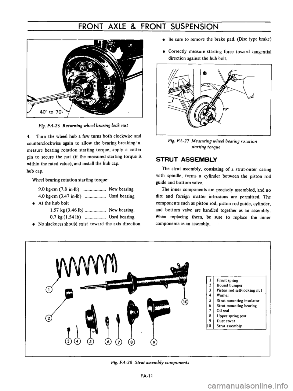
Fig
FA
26
Returning
wheel
bearing
lock
nut
4
Turn
the
wheel
hub
a
few
turns
both
clockwise
and
counterclockwise
again
to
allow
the
bearing
breaking
in
measure
bearing
rotation
starting
torque
apply
a
cotter
pin
to
secure
the
nut
if
the
measured
starting
torque
is
within
the
rated
value
and
install
the
hub
cap
hub
cap
Wheel
bearing
rotation
starting
torque
9
0
kg
cm
7
8
in
1b
4
0
kg
cm
3
4
7
in
1b
At
the
hub
bolt
1
57
kg
3
461b
New
bearing
0
7
kg
1
54lb
Used
bearing
No
slackness
should
exist
toward
the
axis
direction
New
bearing
Used
bearing
J
o
i
@
j
Be
sure
to
remove
the
brake
pad
Disc
type
brake
Correctly
measure
starting
force
toward
tangential
direction
against
the
hub
bolt
Fig
FA
27
Measuring
wheel
bearing
ro
ation
starting
torque
STRUT
ASSEMBLY
The
strut
assembly
consisting
of
a
strut
outer
casing
with
spindle
forms
a
cylinder
between
the
piston
rod
guide
and
bottom
valve
The
inner
components
are
precisely
assembled
and
no
dirt
and
foreign
matter
intrusions
are
permitted
The
components
such
as
piston
rod
piston
rod
guide
cylinder
and
bottom
valve
are
handled
together
as
an
assembly
When
replacing
them
be
sure
to
replace
the
inner
components
as
an
assembly
1
2
3
4
5
6
7
8
9
10
Front
spring
Bound
bumper
Piston
rod
self
locking
nut
Washer
Strut
mounting
insulator
Strut
mounting
bearing
Oil
seal
Upper
spring
seat
Dust
cover
Strut
assembly
Fig
FA
28
Strut
assembly
components
FA
l1