1973 DATSUN B110 mirror
[x] Cancel search: mirrorPage 75 of 513

CHASSIS
Before
inspecting
various
parts
thoroughly
wash
them
so
that
damage
and
wear
can
be
easily
detected
Then
proceed
as
follows
Check
gear
teeth
for
scoring
cracking
and
chipping
and
make
sure
that
tooth
pattern
indicates
correct
meshing
depth
If
any
defect
is
evident
replace
parts
as
required
Note
Drive
pinion
and
drive
gear
are
supplied
for
replacement
as
a
set
therefore
should
either
part
be
damaged
replace
as
a
set
Check
the
pinion
gear
shaft
and
pinion
gear
mating
faces
for
scoring
and
signs
of
wear
and
replace
as
required
Follow
the
same
procedure
for
inner
faces
of
side
gear
and
their
seats
on
differential
case
3
Inspect
all
bearing
races
and
rollers
for
scoring
chipping
or
evidence
of
excessive
wear
They
should
be
in
tiptop
condition
not
worn
with
mirror
like
surfaces
Replace
if
there
is
a
doubt
on
their
efficiency
since
an
incorrect
bearing
operation
may
result
in
noisiness
and
gear
seizure
4
Inspect
thrust
washer
faces
Small
defects
can
be
corrected
with
emery
paper
In
ASSEMBLY
AND
AD
JUSTMENT
Tightening
torque
of
side
bearing
cap
bolts
5
to
6kg
m
36
2
to
43
4
ft
lb
co
g
E
E
on
N
case
the
clearance
between
the
side
gear
and
thrust
washer
exceeds
0
2
mm
0
0079
in
replace
the
thrust
washers
Three
kinds
of
thrust
washers
are
available
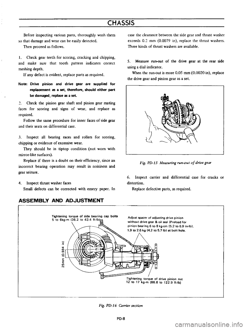
5
Measure
run
out
of
the
drive
gear
at
the
rear
side
using
a
dial
indicator
When
the
run
out
is
more
0
05
mm
0
0020
in
replace
the
drive
gear
and
pinion
gear
as
a
set
Fig
PD
15
Measuring
run
out
of
drive
gear
6
Inspect
carrier
and
differential
case
for
cracks
or
distortion
Replace
defective
parts
as
required
Adjust
spacer
of
adjusting
drive
pinion
without
drive
gear
oil
seal
Preload
for
pinion
bearing
6
to
8
kg
em
5
2
to
6
9
in
Ib
1
9
to
2
6
kg
4
2
to
5
7
Ib
at
bolt
hole
1
Tightening
torque
of
drive
pinion
nut
12
to
17
kg
m
86
8
to
122
9
ft
Ibl
Fig
PD
16
Carrier
section
PO
8
Page 207 of 513

BODY
FRONT
FENDER
AND
FRONT
END
CONTENTS
FRONT
FENDER
Removal
FRONT
BUMPER
BF
17
BF
17
BF
18
FRONT
FENDER
i
RADIATOR
GRILLE
OUTSIDE
MIRROR
BF
18
BF18
1
Front
fender
2
Cowl
top
sealer
3
Front
fender
sealer
4
Cowl
top
5
Side
dash
board
6
Front
pillar
7
Front
bumper
8
Front
bumper
stay
9
Front
bumper
side
bracket
10
Bumper
side
bracket
shim
Removal
Fig
BF
27
Front
fender
and
front
end
components
I
Open
the
hood
disconnect
the
battery
terrninal
for
the
sake
of
safety
and
disconnect
wirings
for
the
head
lamp
and
side
marker
lamp
at
their
connecting
terminals
2
Remove
the
front
bumper
radiator
grille
and
radiator
grille
surround
3
Remove
the
sm
moulding
and
holding
the
fender
remove
it
Fig
BF
28
Removing
front
fender
I
BF
17
Page 208 of 513

BODY
Fig
BF
29
Removing
front
fender
II
FRONT
BUMPER
Remove
six
bolts
retaining
bumper
stay
to
body
and
remove
the
front
bumper
from
the
body
together
with
the
bumper
stay
RADIATOR
GRILLE
Loosen
self
tapping
screws
five
self
tapping
screws
for
sedan
station
wagon
and
van
and
ten
for
coupe
and
remove
the
radiator
grille
frorn
the
body
The
radiator
grille
for
coupe
is
made
of
ABS
resin
Be
careful
not
to
allow
brake
fluid
or
oil
slicking
to
it
7
7f
rl4
o
j
j
iiA
i
DIATIJR
GR
L
SEt
SC
8N
S
i
e
t
II
L
T
RADIATOR
GRill
SET
SCREWS
Fig
BF
30
Removing
radiator
grille
Coupe
OUTSIDE
MIRROR
Indicates
outside
mirror
installing
positions
liMA
t
o
e
O
I
I
Dimen
sIons
Item
A
B
c
D
E
27
to
6
to
Round
shape
817
29
5
25
27
8
dia
6
2
dia
movable
32
2
1
161
0
98431
1
063
to
0
2362
te
mirror
1
094
0
2441
6
to
Round
shape
817
35
40
9
dia
6
2
dia
mirror
32
2
1
378
l
575
0
3543
0
2362
to
0
2441
Unit
mm
in
Fig
BF
31
Fender
mirror
installing
positions
IW
36
l
71
Ta
h
Le
O
II
coo
c
l
2
f
4
5
358
17
77
74
7
Unit
mm
inl
Fig
RF
32
Door
mirror
installing
position
for
right
hand
drive
vehicle
SF
18
Page 209 of 513

BODY
I
1
I
Ik
I
ro
I
W
a
21
zrl
l
11
J
1
3781
I
1
Ii
100
tJ94t
I
100
3
94
0
0551
A
I
10013
94
1
510
0984
100
13
94
I
J
10
1378
2010
787
L
I
l
0
433
O
I
l
JS
348
13
7
5
1
77
Fig
BF
33
Template
for
door
mirror
installation
for
left
hand
drive
vehicle
INSTALLING
OSITION
SECTION
A
A
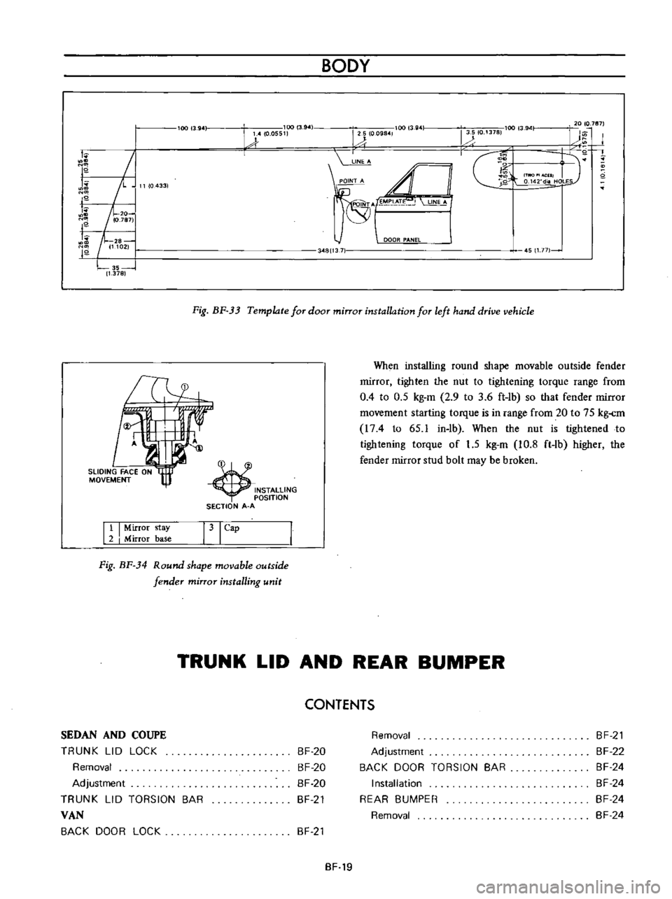
When
installing
round
shape
movable
outside
fender
rnirror
tighten
the
nut
to
tightening
torque
range
from
0
4
to
0
5
kg
m
2
9
to
3
6
ft
lb
so
that
fender
rnirror
rnovernent
starting
torque
is
in
range
from
20
to
75
kg
rn
I74
to
65
1
in
lb
When
the
nut
is
tightened
to
tightening
torque
of
1
5
kg
m
10
8
ft
lb
higher
the
fender
mirror
stud
bolt
may
be
broken
Tl4
11
I
Mirror
stay
2
I
Mirror
base
31
Cap
Fig
BF
34
Round
shape
movable
outside
fender
mirror
installing
unit
TRUNK
LID
AND
REAR
BUMPER
CONTENTS
SEDAN
AND
COUPE
TRUNK
LID
LOCK
Removal
Adjustment
TRUNK
LID
TORSION
BAR
VAN
BACK
DOOR
LOCK
BF
20
BF
20
BF
20
BF
21
Removal
Adjustment
BACK
DOOR
TORSION
BAR
Installation
REAR
BUMPER
Removal
BF
21
BF
22
BF
24
BF
24
BF
24
BF
24
BF
21
BF
19
Page 221 of 513

Installation
Install
the
door
glass
and
regulator
in
reverse
sequence
of
removal
Reinstall
the
seal
screen
after
correctly
adjusting
door
window
closing
SIDE
WINDOW
Removal
I
Remove
the
lock
pillar
moulding
and
remove
the
side
window
handle
set
screws
from
the
body
side
2
Loosen
the
side
window
hinge
installation
screws
and
remove
the
side
window
BODY
7
I
I
I
c
t
2
3
Side
window
glass
Side
window
hinge
Side
hinge
cover
4
Side
window
handle
5
Handle
shim
6
Catch
handle
bracket
Fig
BF
59
Side
window
construction
WINDSHIELD
AND
REAR
WINDOW
CONTENTS
REMOVAL
INSTAllATION
REAR
WINDOW
ELECTRIC
DEFROSTER
Option
SF
31
SF
32
SF
33
REMOVAL
1
Place
a
protective
cover
over
the
hood
front
fenders
instrument
panel
and
front
seat
2
Remove
rear
view
mirror
support
3
Remove
windshield
wiper
arm
assembly
4
On
inside
of
body
loosen
the
lip
of
the
rubber
channel
from
spot
welded
flange
along
the
top
and
sides
of
windshield
opening
With
the
palm
of
the
hand
apply
pressure
to
glass
near
edge
At
the
same
time
use
a
blunt
putty
knife
or
other
suitable
tool
and
carefully
assist
rubber
channel
over
spot
welded
flange
5
After
windshield
rubber
channel
is
free
from
spot
welded
flange
with
aid
of
helper
carefully
lift
windshield
assembly
frorn
body
opening
and
place
it
on
a
protected
bench
Removal
and
installation
Specifications
I
nspection
and
repair
WATERlEAK
CORRECTION
BF
34
SF
34
SF
34
SF
36
Fig
BF
60
Removing
windshield
Note
The
windshield
chrome
moulding
are
installed
in
the
rubber
channel
and
should
be
removed
prior
to
removing
rubber
channel
from
the
gla55
SF
31
Page 326 of 513

EMISSION
CONTROL
AND
TUNE
UP
Appearance
1
First
inspect
whether
vacuum
hoses
are
connected
to
correct
positions
2
Inspect
hoses
for
cracks
distortion
or
plugging
Checking
of
vacuum
motor
I
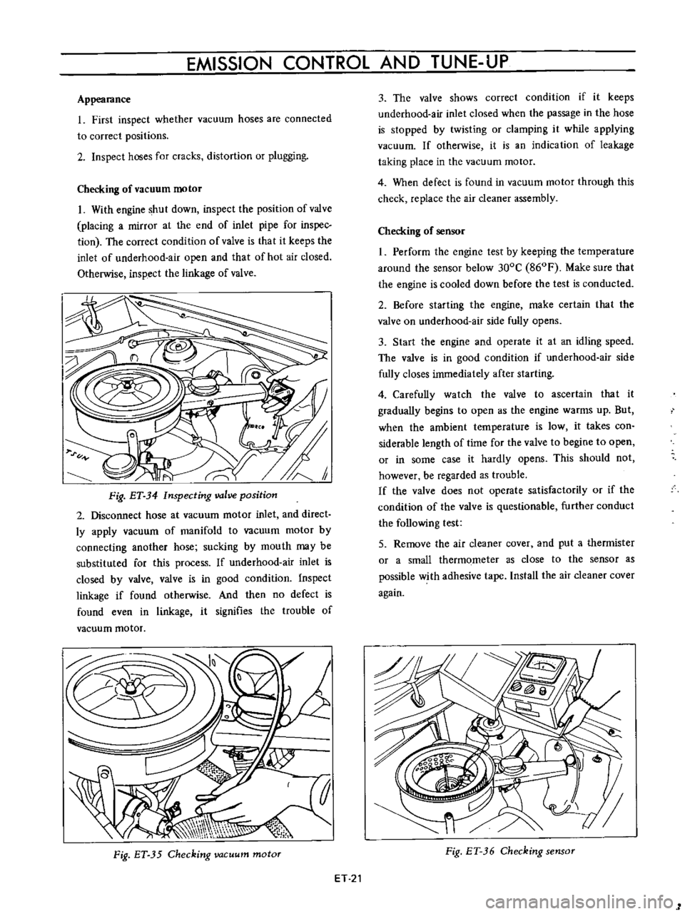
With
engine
shut
down
inspect
the
position
of
valve
placing
a
mirror
at
the
end
of
inlet
pipe
for
inspec
tion
The
correct
condition
of
valve
is
that
it
keeps
the
inlet
of
underhood
air
open
and
that
of
hot
air
closed
Otherwise
inspect
the
linkage
of
valve
Fig
ET
34
Inspecting
valve
position
2
Disconnect
hose
at
vacuum
motor
inlet
and
direct
ly
apply
vacuum
of
manifold
to
vacuum
motor
by
connecting
another
hose
sucking
by
mouth
may
be
substituted
for
this
process
If
underhood
air
inlet
is
closed
by
valve
valve
is
in
good
condition
Inspect
linkage
if
found
otherwise
And
then
no
defect
is
found
even
in
linkage
it
signifies
the
trouble
of
vacuum
motor
Fig
ET
35
Checking
vacuum
motor
ET
21
3
The
valve
shows
correct
condition
if
it
keeps
underhood
air
inlet
closed
when
the
passage
in
the
hose
is
stopped
by
twisting
or
clamping
it
while
applying
vacuum
If
otherwise
it
is
an
indication
of
leakage
taking
place
in
the
vacuum
motor
4
When
defect
is
found
in
vacuum
motor
through
this
check
replace
the
air
cleaner
assembly
Checking
of
sensor
I
Perform
the
engine
test
by
keeping
the
temperature
around
the
sensor
below
300C
860F
Make
sure
that
the
engine
is
cooled
down
before
the
test
is
conducted
2
Before
starting
the
engine
make
certain
that
the
valve
on
underhood
air
side
fully
opens
3
Start
the
engine
and
operate
it
at
an
idling
speed
The
valve
is
in
good
condition
if
underhood
air
side
fully
closes
immediately
after
starting
4
Carefully
watch
the
valve
to
ascertain
that
it
gradually
begins
to
open
as
the
engine
warms
up
But
when
the
ambient
temperature
is
low
it
takes
con
siderable
length
of
time
for
the
valve
to
begine
to
open
or
in
some
case
it
hardly
opens
This
should
not
however
be
regarded
as
trouble
If
the
valve
does
not
operate
satisfactorily
or
if
the
condition
of
the
valve
is
questionable
further
conduct
the
following
test
5
Remove
the
air
cleaner
cover
and
put
a
thermister
or
a
small
thermometer
as
close
to
the
sensor
as
possible
with
adhesive
tape
Install
the
air
cleaner
cover
again
Fig
ET
36
Checking
sensor
1