1973 DATSUN B110 gas type
[x] Cancel search: gas typePage 84 of 513

PROPELLER
SHAFT
DIFFERENTIAL
CARRIER
Incorrect
adjustment
of
bearings
or
gears
Severe
service
due
to
an
excessive
loading
improper
use
of
clutch
Loosened
bolts
and
nuts
such
as
ring
gear
clamp
bolts
Oil
leakage
Worn
out
damaged
or
improperly
driven
front
oil
seal
or
bruised
dented
or
abnormally
worn
slide
face
of
companion
flange
Loosened
bolts
holding
gear
carrier
Defective
gasket
Loosen
filler
or
drain
plug
Clogged
or
damaged
breather
SERVICE
DATA
AND
SPECIFICATIONS
Type
of
differential
gear
carrier
assembly
Final
gear
type
Final
gear
ratio
number
of
teeth
Sedan
Coupe
Van
Drive
pinion
Preload
with
oil
seal
Preload
without
oil
seal
Thickness
of
drive
pinion
adjusting
shims
kg
cm
in
lb
kg
cm
in
lb
mm
in
Pinion
bearing
adjusting
spacer
Ring
gear
Backlash
between
ring
gear
and
pinion
Run
out
of
rear
side
of
ring
gear
mm
in
mm
in
Side
gear
and
pinion
mate
Thickness
of
side
gear
thrust
washers
mm
in
PD
17
Replace
defective
parts
Replace
defective
parts
Replace
defective
parts
Replace
the
defective
oil
seal
Ammend
the
affected
flange
with
sand
paper
or
replace
if
necessary
Tighten
the
bolts
to
specified
torque
Replace
defective
parts
with
new
ones
Tighten
the
plug
Repair
or
replace
H145A
Hypoid
3
900
39
10
7
to
9
6
1
to
7
8
6
to
8
5
2
to
6
9
From
2
74
to
3
25
0
1079
to
0
1280
Spacing
0
Q3
0
0012
Non
adjustable
collapsible
spacer
0
10
to
0
15
0
0039
to
0
0059
Less
than
0
05
0
0020
0
76
to
0
91
0
0299
to
0
0358
Page 302 of 513
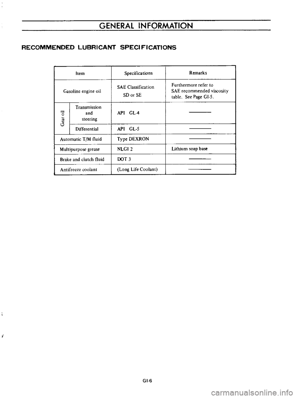
GENERAL
INFORMATION
RECOMMENDED
LUBRICANT
SPECI
FICATIONS
Item
Gasoline
engine
oil
o
Transmission
and
steering
Differential
Automatic
TIM
fluid
Multipurpose
grease
Brake
and
clutch
fluid
Antifreeze
coolant
i
Specifications
SAE
Classification
SO
or
SE
API
G
L
4
API
GL
5
Type
DEXRON
NLGI2
DOT
3
Long
Life
Coolant
GI
6
Remarks
Furthermore
refer
to
SAE
recommended
viscosity
table
See
Page
GI
5
Lithium
soap
base
Page 308 of 513
EMISSION
CONTROL
AND
TUNE
UP
Capacity
Maximum
3
3
L
X
US
gal
y
Imp
gal
2
3
L
US
gal
f
Imp
gal
Minimum
Make
sure
that
engine
oil
is
not
deteriorated
with
cooling
water
or
gasoline
Drain
and
refill
the
oil
if
necessary
Notes
a
A
milky
oil
indicates
the
presence
of
cooling
water
Find
the
cause
for
necessary
corrective
action
b
Oil
with
extremely
low
viscosity
indicates
dilution
with
gasoline
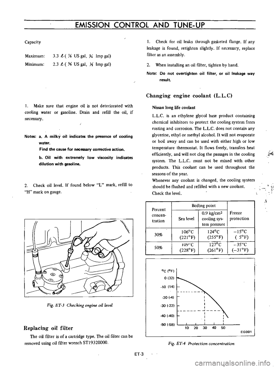
2
Check
oil
level
If
found
below
L
mark
refill
to
H
mark
on
gauge
Fig
ET
3
Checking
engine
oil
level
Replacing
oil
filter
The
oil
ftIter
is
of
a
cartridge
type
The
oil
filter
can
be
removed
using
oil
ftIter
wrench
STl9320000
Check
for
oil
leaks
through
gasketed
flange
If
any
leakage
is
found
retighten
slightly
If
necessary
replace
filter
as
an
assembly
2
When
installing
an
oil
filter
tighten
by
hand
Note
Do
not
overtighten
oil
filter
or
oil
leakage
way
result
Changing
engine
coolant
L
L
C
Nissan
long
life
coolant
LLC
is
an
ethylene
glycol
base
product
containing
chemical
inhibitors
to
protect
the
cooling
system
from
rusting
and
corrosion
The
L
L
C
does
not
contain
any
glycerine
ethyl
or
methyl
alcohol
It
will
not
evaporate
or
boil
away
and
can
be
used
with
either
high
or
low
temperature
thermostat
It
flows
freely
transfers
heat
efficiently
and
will
not
clog
the
passages
in
the
cooling
system
The
LL
C
must
not
be
mixed
with
other
products
This
coolant
can
be
used
throughout
tlie
seasons
of
the
year
Whenever
any
coolant
is
changed
the
cooling
system
should
be
flushed
and
refilled
with
a
new
coolant
Check
the
level
J
Percent
Boiling
point
0
9
kgfcm2
Freeze
concen
tration
Sea
level
cooling
sys
protection
tern
pressure
30
1060
C
I
240C
15OC
221OF
255OF
5OF
50
IUY
C
1270C
35
C
2280
F
2610F
3IOF
DC
OF
0
321
10
14
20141
50
58
I
I
I
I
1
I
I
1
30
1
22
40
401
40
10
30
50
20
EGOOl
Fig
ET
4
Protection
concentration
ET
3
Page 343 of 513
ENGINE
MECHANICAL
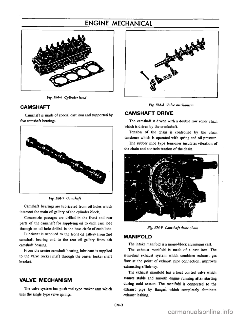
Fig
EM
6
Cylinder
head
CAMSHAFT
Camshaft
is
made
of
special
cast
iron
and
supported
by
five
cannshaft
bearings
1
1
f
r
f
r
I
Fig
EM
Camshaft
Camshaft
bearings
are
lubricated
from
oil
holes
which
intersect
the
main
oil
gallery
of
the
cylinder
block
Concentric
passages
are
drilled
in
the
front
and
rear
parts
of
the
camshaft
for
supplying
oil
to
each
cam
lobe
through
an
oil
hole
drilled
in
the
base
circle
of
each
lobe
Lubricant
is
supplied
to
the
front
oil
gallery
from
2nd
camshaft
bearing
and
to
the
rear
oil
gallery
from
4th
camshaft
bearing
From
the
center
camshaft
bearing
lubricant
is
supplied
to
the
valve
rocker
shaft
through
the
center
locker
shaft
bracket
VALVE
MECHANISM
The
valve
system
has
push
rod
type
rocker
arm
which
uses
the
single
type
valve
springs
a
Fig
EM
8
Vol
mechanism
CAMSHAFT
DRIVE
The
camshaft
is
driven
with
a
double
row
roller
chain
which
is
driven
by
the
crankshaft
Tension
of
the
chain
is
controlled
by
the
chain
tensioner
which
is
operated
with
spring
and
oil
pressure
The
rubber
shoe
type
tensioner
insulates
vibration
of
the
chain
and
controls
tension
of
the
chain
Fig
EM
9
Comshdft
drive
chain
MANIFOLD
The
intake
manifold
is
a
mono
block
aluminum
cast
The
exhaust
manifold
is
made
of
a
cast
iron
The
semi
dual
exhaust
system
which
combines
exhaust
gas
flow
at
the
point
of
exhaust
pipe
connection
improves
exhausting
efficiency
The
exhaust
manifold
has
a
heat
control
valve
which
assures
stable
and
smooth
engine
running
after
starting
during
cold
season
The
manifold
is
connected
to
the
exhaust
pipe
by
flanges
which
completely
eliminate
exhaust
leaking
EM
3
Page 370 of 513
ENGINE
17
Install
the
oil
strainer
and
the
oil
pan
using
the
gasket
Apply
sealing
agent
on
hath
surfaces
of
the
gasket
especially
on
the
front
and
rear
portions
of
the
oil
pan
Oil
pan
tightening
torque
0
4
to
0
6
kg
m
I
9
to
4
3
ft
lbJ
I
R
I
nvcrt
the
engine
and
install
the
cylinder
head
assembly
and
gasket
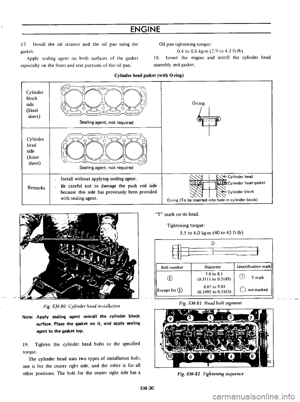
Cylinder
head
gasket
with
O
ring
Cylinder
block
side
Steel
sheet
D
QCO
0
0
i
O
1
nrr
11
I
Li
I
I
Vo
o
f
C
C
r
c
Sealing
agent
not
required
Cylinder
head
side
Joint
sheet
Remarks
Install
without
applying
sealing
agent
Be
careful
not
to
damage
the
push
rod
side
because
this
side
has
previously
been
provided
with
sealing
agent
Fig
EM
80
Cy
linder
head
installatjo
1
Note
Apply
sealing
agent
overall
the
cylinder
block
surface
Place
the
gasket
on
it
and
apply
sealing
agent
to
the
gasket
top
19
Tighten
the
cylinder
head
bolts
to
the
specified
torque
The
cylinder
head
uses
two
types
of
installation
bolt
one
is
for
the
center
right
side
and
the
other
is
for
all
other
positions
The
bolt
for
the
center
right
side
has
a
O
ring
j
I
Y
J
CYlinder
head
I
I
Cvlinderheadgasket
I
Cylinder
block
O
ring
To
be
inserted
into
hole
in
cylinder
block
T
mark
on
its
head
Tightening
torque
5
5
to
6
0
kg
m
40
to
43
ft
lb
fI
J
D
Bolt
number
Diameter
Identification
mark
CD
7
9
to
8
1
1
0
3111
to
0
3189
T
mark
Except
for
CD
8
87
to
9
03
o
not
marked
0
3492
to
0
3555
Fig
EM
8t
Head
bolt
segment
l
Fig
EM
82
Tightening
sequenc
EM
3D
Page 384 of 513
ENGINE
LUBRICATION
SYSTEM
Inspection
and
repair
Clean
the
disassembled
parts
with
cleaning
solvent
and
inspect
for
defects
Inspect
the
drive
rotor
shaft
for
excessive
wear
and
scores
and
check
the
following
clearances
Side
clearance
between
Quter
and
inner
rotors
0
12
mm
0
0047
in
or
below
Tip
clearance
0
04
to
0
I2mm
0
0016
to
0
0047
in
Clearance
between
outer
rotor
and
body
0
15
to
0
21
rom
0
0059
to
0
0083
in
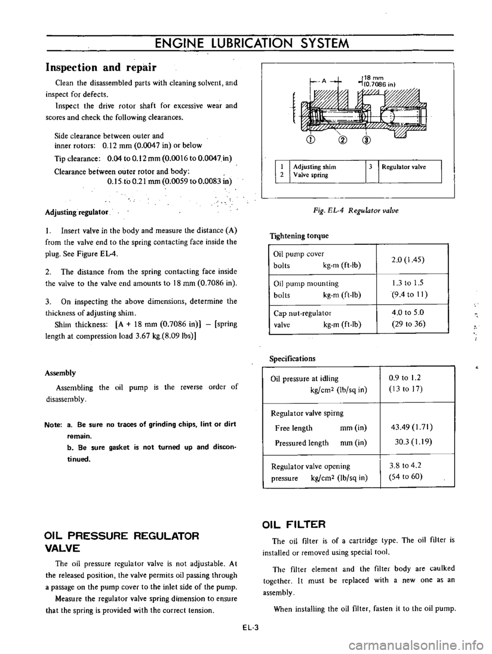
Adjusting
regulator
Insert
valve
in
the
body
and
measure
the
distance
A
from
the
valve
end
to
the
spring
contacting
face
inside
the
plug
See
Figure
EL
4
2
The
distance
from
the
spring
contacting
face
inside
the
valve
to
the
valve
end
amounts
to
18
mm
0
7086
in
3
On
inspecting
the
above
dimensions
determine
the
thickness
of
adjusting
shim
Shim
thickness
A
18
mm
0
7086
in
spring
length
at
compression
load
3
67
kg
8
091bs
Assembly
Assembling
the
oil
pump
is
the
reverse
order
of
disassembly
Note
3
Be
sure
no
traces
of
grinding
chips
lint
or
dirt
remain
b
Be
sure
gasket
is
not
turned
up
and
discon
tinued
OIL
PRESSURE
REGULATOR
VALVE
The
oil
pressure
regulator
valve
is
not
adjustable
At
the
released
position
the
valve
permits
oil
passing
through
a
passage
on
the
pump
cover
to
the
inlet
side
of
the
pump
Measure
the
regulator
valve
spring
dimension
to
ensure
that
the
spring
is
provided
with
the
correct
tension
e
Q
@
I
I
Adjusting
shim
2
Valve
spring
13
I
RegulatoT
valve
Fig
EL
4
RegulatoT
valve
Tightening
torque
Oil
pump
cover
bolts
kg
m
ft
lb
2
0
1
45
Oil
pump
mounting
bolts
kg
m
ft
lb
13
to
1
5
9
4to
II
Cap
nut
regulator
valve
kg
m
ft
lb
4
0
to
5
0
29
to
36
Specifications
Oil
pressure
at
idling
kgfcm2
Ibfsq
in
0
9
to
1
2
13
to
17
Regulator
valve
spirng
Free
length
mm
in
Pressured
length
mm
in
4349
l71
30
3
I
19
Regulator
valve
opening
pressure
kgfcm2
lbfsq
in
3
8
to
4
2
54
to
60
OIL
FILTER
The
oil
filter
is
of
a
cartridge
type
The
oil
filter
is
installed
or
removed
using
special
tool
The
filter
element
and
the
filter
body
are
caulked
together
I
t
must
be
replaced
with
a
new
one
as
an
assembly
When
installing
the
oil
filter
fasten
it
to
the
oil
pump
EL
3
Page 385 of 513
ENGINE
Note
Do
not
oyerlasten
the
filter
or
oil
leakage
may
occur
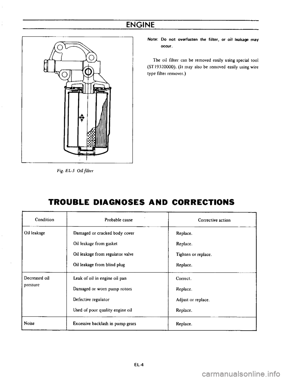
The
oil
filter
can
be
removed
easily
using
special
tool
STl9320000
It
may
also
be
removed
easily
using
wire
type
filter
remover
l
t
1
h
T
Fig
EL
5
Oil
filteT
TROUBLE
DIAGNOSES
AND
CORRECTIONS
Condition
Probable
cause
Corrective
action
Oil
leakage
Damaged
or
cracked
body
cover
Replace
Oil
leakage
from
gasket
Replace
Oil
leakage
from
regulator
valve
Tighten
or
replace
Oil
leakage
from
blind
plug
Replace
Decreased
oil
Leak
of
oil
in
engine
oil
pan
Correct
pressure
Damaged
or
worn
pump
rotors
Replace
Defective
regulator
Adjust
or
replace
Used
of
poor
quality
engine
oil
Replace
Noise
Excessive
backlash
in
pump
gears
Replace
EL
4
Page 396 of 513

FUEl
SYSTEM
FUEL
STRAINER
DESCRIPTION
The
fuel
strainer
is
of
a
cartridge
type
It
uses
paper
element
as
strainer
element
which
can
be
checked
for
condition
from
outside
This
strainer
cannot
be
cleaned
Replace
the
strainer
at
the
specified
service
interval
or
if
it
becomes
clogged
or
restricted
REMOVAL
Disconnect
inlet
and
outlet
fuel
lines
from
fuel
strainer
and
remove
fuel
strainer
Note
Before
disconnecting
fuel
lines
use
a
container
to
receive
the
remaining
fuel
in
lines
r
@
I
I
Il
QY
I
I
I
elementl
3
Cover
@
EF005
Fig
EF
10
Sectional
view
of
caTtridge
type
fuel
stTaineT
FUEL
PUMP
CONTENTS
DESCRIPTION
FUEL
PUMP
TESTING
Static
pressure
test
Capacity
test
EF
5
EF
6
EF
6
EF
6
DESCRIPTION
The
fuel
pump
transfers
gasoline
from
the
tank
to
the
carburetor
in
sufficient
quantity
to
meet
engine
require
ments
at
any
speed
or
load
The
fuel
pump
is
of
the
diaphragm
type
REMOVAL
AND
DISASSEMBLY
INSPECTION
ASSEMBLY
EF
7
EF
B
EF
B
The
fuel
pump
consists
of
a
body
rocker
arm
and
link
assembly
fuel
diaphragm
fuel
diaphragm
spring
seal
inlet
and
outlet
valves
The
fuel
diaphragm
consists
of
specially
treated
rubber
which
is
not
affected
by
gasoline
held
together
with
two
metal
discs
and
a
pull
rod
EF
5