1973 DATSUN B110 Charging system
[x] Cancel search: Charging systemPage 241 of 513
INSPECTION
Referring
to
the
wiring
diagram
check
the
wiring
harness
for
connection
with
electrical
equipment
and
connector
for
conned
ion
and
installation
When
checking
the
wiring
harness
note
the
following
matters
Connected
unit
should
not
be
loose
rusted
or
contaminated
2
Cable
insulator
cover
should
not
be
damaged
crack
ed
or
insulating
material
should
not
be
deteriorated
3
For
those
parts
which
are
grounded
through
the
installation
bolts
the
bolts
should
be
in
contact
with
the
body
completely
so
that
continuity
is
provided
in
between
the
body
and
bolts
4
Terminals
of
unit
through
which
current
flows
should
not
come
into
contact
with
other
metal
parts
5
No
erroneous
connection
should
be
present
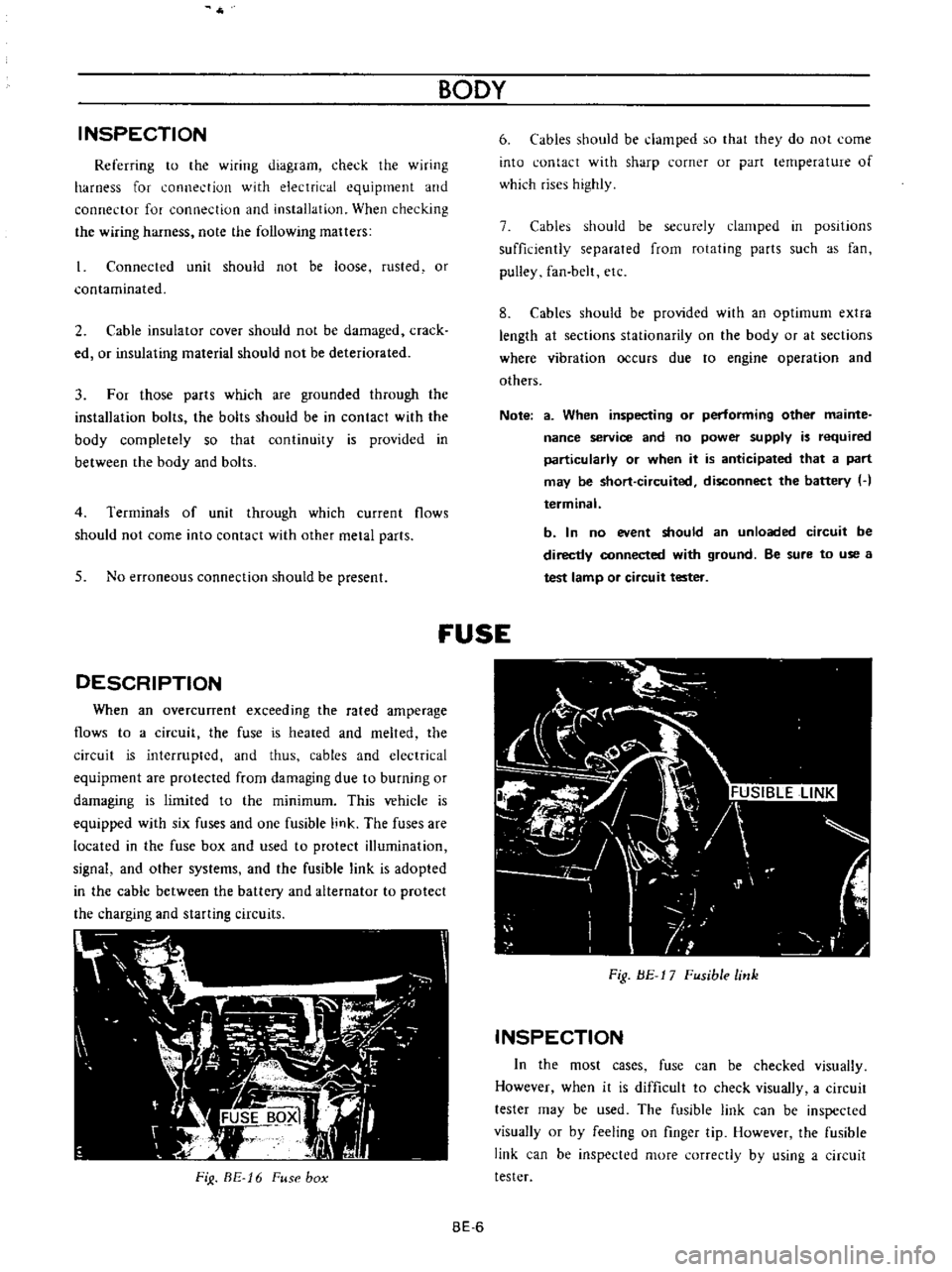
DESCRIPTION
When
an
overcunent
exceeding
the
rated
amperage
flows
to
a
circuit
the
fuse
is
heated
and
melted
the
circuit
is
interrupted
and
thus
cables
and
electrical
equipment
are
protected
from
damaging
due
to
burning
or
damaging
is
limited
to
the
minimum
This
vehicle
is
equipped
with
six
fuses
and
one
fusible
link
The
fuses
are
located
in
the
fuse
box
and
used
to
protect
illumination
signal
and
other
systems
and
the
fusible
link
is
adopted
in
the
cable
between
the
battery
and
alternator
to
protect
the
charging
and
starting
circuits
FiJ
BE
16
Fuse
box
BODY
6
Cables
should
be
damped
so
that
they
do
not
come
into
contact
with
sharp
corner
or
part
lernperature
of
which
rises
highly
7
Cables
should
be
securely
clamped
in
posItions
sufficiently
separated
from
rotating
parts
such
as
fan
pulley
fan
belt
etc
8
Cables
should
be
provided
with
an
optimum
extra
length
at
sections
stationarity
on
the
body
or
at
sections
where
vibration
occurs
due
to
engine
operation
and
others
Note
a
When
inspecting
or
performing
other
mainte
nance
service
and
no
power
supply
is
required
particularly
or
when
it
is
anticipated
that
a
part
may
be
short
circuited
disconnect
the
battery
H
terminal
b
In
no
event
should
an
unloaded
circuit
be
directly
connected
with
ground
Be
sure
to
use
a
test
lamp
or
circuit
tester
fUSE
Fig
BE
17
Fusible
link
INSPECTION
In
the
most
cases
fuse
can
be
checked
visually
However
when
it
is
difficult
to
check
visually
a
circuit
tester
may
be
used
The
fusible
link
can
be
inspected
visually
or
by
feeling
on
finger
tip
However
the
fusible
link
can
be
inspected
more
correctly
by
using
a
circuit
tester
BE
6
Page 248 of 513
BODY
ELECTRICAL
Main
high
beam
Defective
dimmer
switch
cannot
be
switch
ed
to
dimmer
low
beam
or
vice
versa
Head
lamps
dim
Defective
light
circuit
Head
lamps
dim
Partly
discharged
battery
when
the
engine
is
stopped
or
op
era
ted
under
idling
speed
Defective
battery
Head
lamps
still
Faulty
sealed
beam
unit
dim
with
engine
run
above
idling
speed
Faulty
charging
system
Head
light
in
only
one
side
lights
Faulty
head
lamp
terrnianl
con
tact
Defective
lamp
Turn
signal
lamps
Probable
Condition
cause
All
turn
signal
Blown
fuse
or
faulty
contact
lamps
do
not
light
When
red
yellow
cable
is
con
nected
to
red
white
cable
or
red
black
cable
and
the
main
beam
or
dimmer
beam
lights
the
circuit
is
nonnal
The
dimmer
switch
is
defective
Check
the
head
light
circuit
for
cable
being
about
to
break
and
faulty
contact
or
check
fuse
for
faulty
contact
Measure
specific
gravity
of
elec
trolyte
Voltage
between
head
lamp
red
white
cable
and
red
cable
ter
minals
is
12
8V
or
higher
Voltage
is
less
than
12
8V
through
above
test
Method
of
inspection
Check
the
fuse
for
fusing
and
faulty
contact
BE
13
Conduct
continuity
test
and
if
the
dirn
mer
switch
is
defec
tive
replace
Repair
or
replace
if
required
Charge
battery
if
required
Replace
battery
Replace
sealed
beam
units
Check
the
generator
regulator
and
light
circuit
Repair
as
required
Replace
lamp
Corrective
action
When
the
fuse
is
fused
detect
and
repair
the
cause
and
replace
the
fuse
Page 261 of 513

The
lamp
does
not
go
out
when
the
engine
is
started
Faulty
charging
system
BODY
Inspect
the
charging
system
WINDSHIELD
WIPER
AND
WASHER
Description
Wiper
motor
replacement
Wiper
blade
operating
range
CONTENTS
BE
26
BE
27
BE
27
Description
The
windshield
wipers
consist
of
wiper
motor
link
mechanism
wiper
arms
and
blades
The
wiper
motor
unit
consists
of
a
motor
and
auto
stop
mechanism
The
wiper
rnotor
is
of
a
2
speed
type
When
the
wiper
switch
knob
is
pulled
to
the
I
st
step
the
windshield
wipers
operate
at
low
speed
and
when
pulled
to
the
2nd
step
operate
at
high
speed
The
wiper
motor
unit
is
located
on
the
cowl
dash
in
BATTERY
Cl
WIPER
MOTOR
rrQ
J
WASHER
MOTOR
IB
ILRI
L
CJ
LA
t
Y
I
Ll
j
IBI
1
f
I
LW
I
Wiper
washer
switch
replacement
Washer
nozzle
adjustment
TROUBLE
OIAGNOSES
ANO
CORRECTIONS
BE
27
BE
27
BE
28
the
engine
compartment
and
the
link
mechanism
is
located
behind
the
instrument
panel
The
electrically
operated
windshield
washer
consists
of
washing
fluid
lank
with
rnotor
and
pump
washer
nozzles
and
vinyl
tube
used
to
connect
those
compo
nents
The
windshield
washer
switch
is
combined
with
the
windshield
wiper
switch
to
a
single
unit
When
operating
the
washer
twist
the
switch
knob
IG
FUSE
W
v
l
i
f
WIPER
SWITCH
10FFI
I
2
I
TWIST
I
y
ILl
I
b
I
J
6
I
BLII
Fig
BE
43
Circuit
diagram
for
windshield
wiper
washer
system
BE
26
Page 268 of 513
BODY
ELECTRICAL
Distributor
Secure
ground
of
ignition
coil
Secure
contact
of
carbon
electric
pole
and
rotor
Eliminate
excessive
tip
on
the
rotor
pole
or
cap
pole
by
scrubbing
with
a
screwdriver
Check
stagger
between
rotor
and
stator
Charging
system
Sound
of
alternating
current
pre
sents
Alternator
Install
a
0
5
l
F
capacitor
on
charging
terminal
A
Note
Do
not
use
capacitor
ex
cessively
If
capacity
is
used
ex
cessively
the
alternator
coil
will
be
broken
When
the
accelerator
pedal
is
de
pressed
or
released
noise
presents
Regulator
Install
a
0
5
l
F
capacitor
on
A
terrninal
of
the
voltage
regulator
Supplement
equipment
When
engine
starts
noise
presents
Noise
still
presents
even
after
stopping
the
engine
Operative
noise
of
ther
rnometer
and
fuel
gauge
Install
0
1
l
F
capacitor
between
terminal
and
ground
wire
Note
If
a
capacitor
having
ex
cessive
capacity
is
used
indi
cation
of
meter
will
be
devi
ated
Noise
presents
when
horn
is
blown
Horn
Install
a
0
5
IF
capacitor
on
the
horn
relay
terminal
or
horn
switch
Noise
presents
when
turn
signal
lamps
are
operated
Flasher
unit
Install
a
0
5
l
F
capacitor
Note
a
Be
sure
to
locate
capacitor
most
near
position
of
noise
source
and
connect
in
parallel
completely
d
Make
installation
and
conneCtion
securely
b
Cut
lead
wire
as
short
as
possible
c
Ground
wire
should
be
placed
on
the
body
e
Carefully
identify
marks
IN
or
OUT
BE
33
Page 420 of 513
DATSUN
1200
MODEL
B
11
0
SERIES
L
NISSAN
I
NISSAN
MOTOR
CO
LTD
TOKYO
JAPAN
SECTION
EE
ENGINE
ELECTRICAL
SYSTEM
BATTERY
STARTING
MOTOR
CHARGING
CIRCUIT
ALTERNATOR
REGULATOR
IGNITIO
N
CIRCUIT
DISTRIBUTOR
IGNITION
COIL
SPARK
PLUG
EEl
EE
3
EE
15
EE
16
EE
23
EE
29
EE
29
EE
36
EE
37
Page 421 of 513
ENGINE
ElECTRICAL
SYSTEM
BATTERY
CONTENTS
REMOVAL
CHECKING
ELECTROLYTE
LEVEL
CHECKING
SPECIFIC
GRAVITY
EE
1
EE
l
EE
1
REMOVAL
Disconnect
the
negative
terminal
first
and
then
the
positive
terminal
2
Remove
the
retainer
nuts
and
take
off
retainer
3
Release
retainer
bolts
and
remove
battery
CHECKING
ELECTROLYTE
LEVEL
Adjust
the
electrolyte
level
in
the
battery
when
the
battery
is
in
a
fully
charged
condition
The
electrolyte
hould
maintain
its
indicated
correct
level
in
the
battery
N
water
other
than
distilled
water
should
be
added
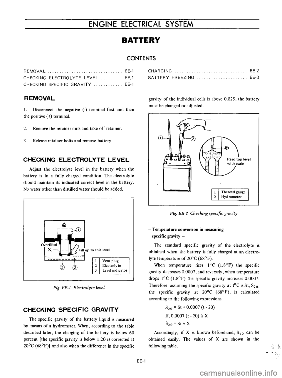
Q
cD
I
1
Vent
plug
2
Electrolvte
3
Level
indicator
Fig
EE
1
ElectTolyte
level
CHECKING
SPECIFIC
GRAVITY
The
specific
gravity
of
the
battery
liquid
is
measured
by
means
of
a
hydrometer
When
according
to
the
table
described
later
the
charging
of
the
battery
is
below
60
percent
the
specific
gravity
is
below
1
20
as
corrected
at
200e
680F
and
also
when
the
difference
in
the
specific
CHARGING
BATTERY
FREEZING
EE
2
EE
3
gravity
of
the
individual
cells
is
above
0
025
the
battery
must
be
changed
or
adjusted
tl
f
ead
p
level
jSCale
2
II
It
I
TheTmat
gauge
I
2
Hydrometer
Fig
EE
2
Checking
specific
gTavity
Temperature
conversion
in
measuring
specific
gravity
The
standard
specific
gravity
of
the
electrolyte
is
obtained
when
the
battery
is
fully
charged
at
an
electro
lyte
temperature
of
200
e
680
F
When
temperature
rises
loe
1
80F
the
specific
gravity
decreases
0
0007
and
reversely
when
temperature
drops
loe
I
ROF
the
specific
gravity
increases
0
0007
Therefore
assuming
the
specific
gravity
at
tOe
is
St
S20
the
specific
gravity
at
200e
680F
is
calculated
according
to
the
following
expressions
S
o
St
0
0007
t
20
If
0
0007
t
20
is
X
S
o
St
X
Accordingly
if
X
is
known
beforehand
S
o
can
be
obtained
easily
The
values
of
X
are
shown
in
the
following
table
EE
1
Page 423 of 513
ENGINE
ElECTRICAL
SYSTEM
5
If
the
specific
gravity
is
above
1
260
200C
or
680F
after
charging
adjust
it
by
adding
distilled
water
6
Keep
any
open
flame
away
from
the
place
where
the
battery
is
being
charged
7
Replace
vent
plugs
and
clean
the
upper
face
of
the
battery
after
charging
BATTERY
FREEZING
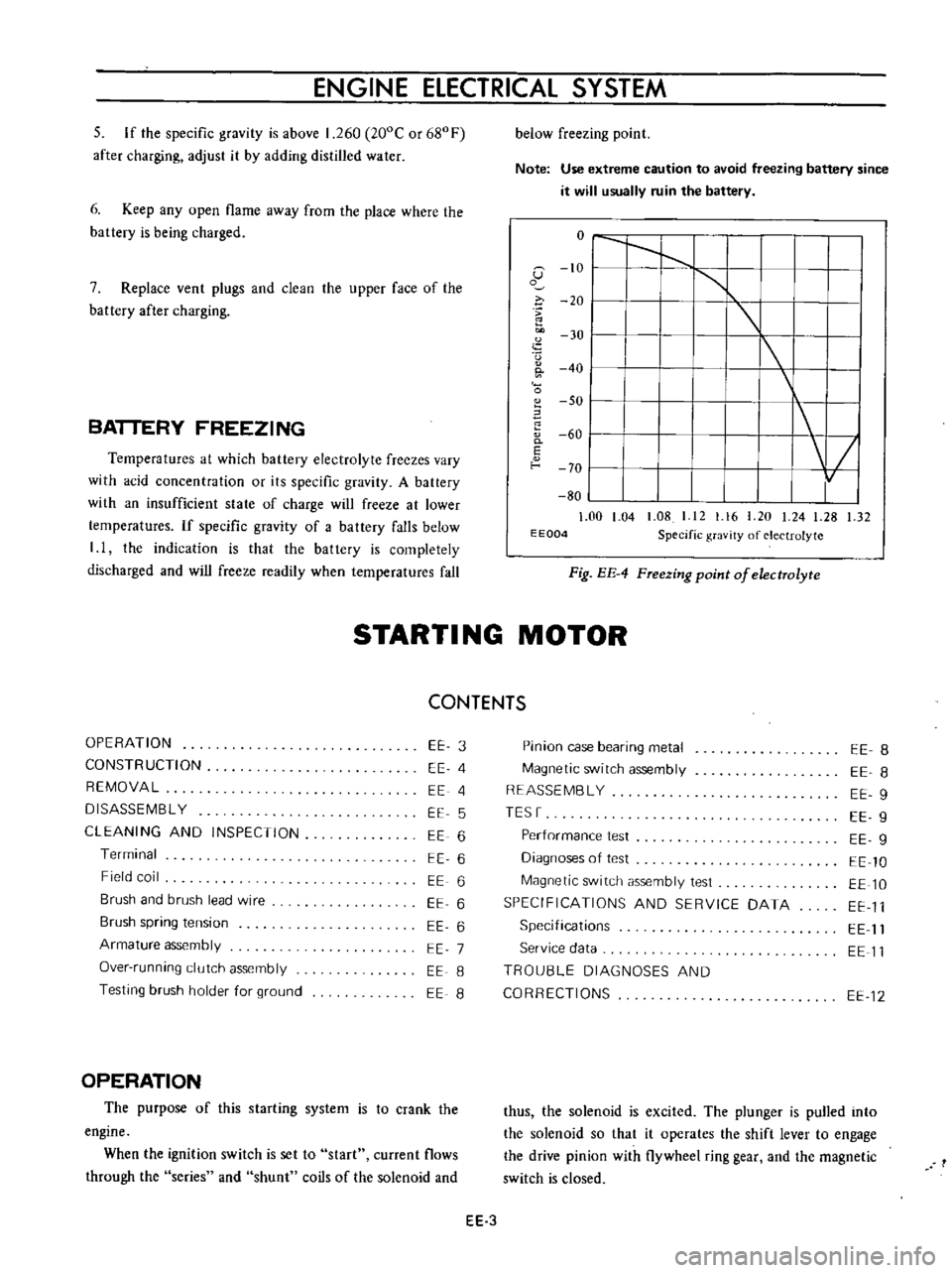
Temperatures
at
which
battery
electrolyte
freezes
vary
with
acid
concentration
or
its
specific
gravity
A
battery
with
an
insufficient
state
of
charge
will
freeze
at
lower
temperatures
If
specific
gravity
of
a
battery
falls
below
I
I
the
indication
is
that
the
battery
is
completely
discharged
and
will
freeze
readily
when
temperatures
fall
below
freezing
point
Note
Use
extreme
caution
to
avoid
freezing
battery
since
it
will
usually
ruin
the
battery
o
I
I
1
G
10
I
1
o
i
20
I
u
30
I
I
0
40
I
0
SO
I
60
0
I
E
f
o
70
I
80
1
00
1
04
1
08
I
12
1
16
20
24
1
28
1
32
E
E004
Specific
gravity
of
electrolyte
Fig
EE
4
FTeezing
point
of
electrolyte
STARTI
NG
MOTOR
CONTENTS
OPERATION
CONSTRUCTION
REMOVAL
DISASSEMBL
Y
CLEANING
AND
INSPECTION
Terminal
Field
coil
Brush
and
brush
lead
wire
Brush
spring
tension
Armature
assembly
Over
running
clutch
assembly
Testing
brush
holder
for
ground
EE
3
EE
4
EE
4
EE
5
EE
6
EE
6
EE
6
EE
6
EE
6
EE
7
EE
8
EE
8
OPERATION
The
purpose
of
this
starting
system
is
to
crank
the
engine
When
the
ignition
switch
is
set
to
start
current
flows
through
the
series
and
shunt
coils
of
the
solenoid
and
Pinion
case
bearing
metal
Magnetic
switch
assembly
REASSEMBL
Y
TESr
Performance
test
Diagnoses
of
test
Magnetic
switch
assembly
test
SPECIFICATIONS
AND
SERVICE
DATA
Specifications
Service
data
TROU8LE
DIAGNOSES
AND
CORRECTIONS
EE
8
EE
8
EE
9
EE
9
EE
g
EE
10
EE
10
EE
11
EE
11
EE
11
EE
12
thus
the
solenoid
is
excited
The
plunger
is
pulled
into
the
solenoid
so
that
it
operates
the
shift
lever
to
engage
the
drive
pinion
with
flywheel
ring
gear
and
the
magnetic
switch
is
closed
EE
3
Page 433 of 513
Magnetic
switch
operating
sound
is
heard
The
starting
motor
rotates
Pinion
gear
does
not
intermesh
with
ring
gear
ENGINE
ELECTRICAL
SYSTEM
Starter
Magnetic
switch
Battery
Wiring
Starting
motor
Magnetic
switch
Ring
gear
Starting
motor
Broken
armature
or
field
coil
cable
Broken
brush
pig
tail
Defective
mica
Broken
or
shorted
series
coil
Faulty
plunger
sliding
Over
discharging
Faulty
terminal
contact
or
loose
connection
Faulty
B
or
M
terminal
connections
Shorted
armature
or
field
coil
Worn
brush
or
improper
spring
pressure
Contaminated
commutator
or
de
fective
mica
Faulty
brush
connection
Seized
metal
Armature
contacted
with
pole
core
Insufficient
plunger
L
dimension
Faulty
contact
Broken
or
shorted
shunt
coil
wire
Worn
teeth
Weakened
pinion
sleeve
spring
Worn
pinion
teeth
EE
13
Replace
Replace
Correct
or
replace
Replace
Repair
or
replace
Measure
specific
gravity
of
electrolyte
arid
charge
if
necessary
Clean
and
retighten
Retighten
Repair
or
replace
Repair
or
replace
Clean
or
repair
Repair
Replace
Repair
or
replace
Adjust
Replace
Replace
Replace
Replace
Replace