1973 DATSUN B110 length
[x] Cancel search: lengthPage 45 of 513
Adjustment
of
front
end
play
Select
front
clutch
thrust
washer
by
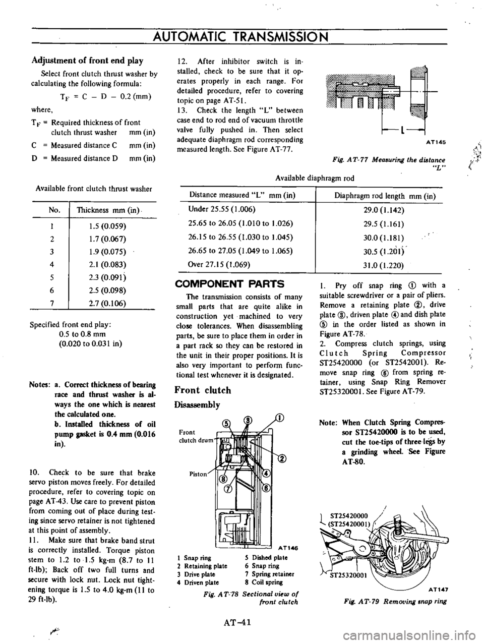
calculating
the
following
formula
TF
C
D
0
2
mm
where
T
F
Required
thickness
of
front
clutch
thrust
washer
mm
in
C
Measured
distance
C
mm
in
D
Measured
distance
D
mm
in
Available
front
clutch
thrust
washer
No
Thickness
mm
in
I
J
5
0
059
2
1
7
0
067
3
1
9
0
075
4
2
1
0
083
5
2
3
0
091
6
2
5
0
098
7
2
7
0
106
Specified
front
end
play
0
5
to
0
8
mm
0
020
to
0
031
in
Notes
a
Correct
thickness
of
bearing
race
and
thrust
washer
is
al
ways
the
one
which
is
nearest
the
calculated
one
b
Installed
thickness
of
oil
pump
gasket
is
0
4
mm
0
016
in
10
Check
to
be
sure
that
brake
servo
piston
moves
freely
For
detailed
procedure
refer
to
covering
topic
on
page
AT
43
Use
care
to
prevent
piston
from
coming
out
of
place
during
test
ing
since
servo
retainer
is
not
tightened
at
this
point
of
assembly
II
Make
sure
that
brake
band
strut
is
correctly
installed
Torque
piston
stem
to
1
2
to
1
5
kg
m
8
7
to
II
ft
lb
Back
off
two
full
turns
and
secure
with
lock
nut
Lock
nut
tight
ening
torque
is
1
5
to
4
0
kg
m
I
I
to
29
ft
Ib
AUTOMATIC
TRANSMISSION
I
2
After
inhibitor
switch
is
in
stalled
check
to
be
sure
that
it
op
erates
properly
in
each
range
For
detailed
procedure
refer
to
covering
topic
on
page
AT
51
13
Check
the
length
L
between
case
end
to
rod
end
of
vacuum
throttle
valve
fully
pushed
in
Then
select
adequate
diaphragm
rod
corresponding
measured
length
See
Figure
AT
77
m
rj
I
L
1
AT145
i
Fig
AT
77
Measuring
the
distance
L
Available
diaphragm
rod
Distance
measured
L
mm
in
Under
25
55
1
006
25
65
to
26
05
1
010
to
1
026
26
15
to
26
55
1
030
to
1
045
26
65
to
27
05
1
049
to
1
065
Over
27
15
1
069
COMPONENT
PARTS
The
transmission
consists
of
many
small
parts
that
are
quite
alike
in
construction
yet
machined
to
very
close
tolerances
When
disassembling
parts
be
sure
to
place
them
in
order
in
a
part
rack
so
they
can
be
restored
in
the
unit
in
their
proper
positions
It
is
also
very
important
to
perform
func
tional
test
whenever
it
is
designated
Front
clutch
Disassembly
Front
clutch
drum
Piston
1
AT146
1
Snap
ring
S
Dished
plate
2
Retaining
plate
6
Snap
ring
3
Drive
plate
7
Spring
retainer
4
Driven
plate
8
Coil
spring
Fig
AT
78
S
ctional
v
w
of
front
clutch
AT
41
Diaphragm
rod
length
mm
in
29
0
1
142
29
5
1
161
30
0
1
181
30
5
1
2
1I
31
0
1
220
I
Pry
off
snap
ring
D
with
a
suitable
screwdriver
or
a
pair
of
pliers
Remove
a
retaining
plate
@
drive
plate
@
driven
plate
@and
dish
plate
@
in
the
order
listed
as
shown
in
Figure
AT
78
2
Compress
clutch
springs
using
Clutch
Spring
Compressor
ST25420000
or
ST2542001
Re
move
snap
ring
@
from
spring
re
tainer
using
Snap
Ring
Remover
ST25320001
See
Figure
AT
79
Note
When
Clutch
Spring
Compres
sor
STIS420000
is
to
be
used
cut
the
toe
tips
of
threeloigs
by
a
grinding
wheel
See
Figure
AT
80
AT
1
Fig
AT
79
RemoL
ing
snap
ring
Page 51 of 513
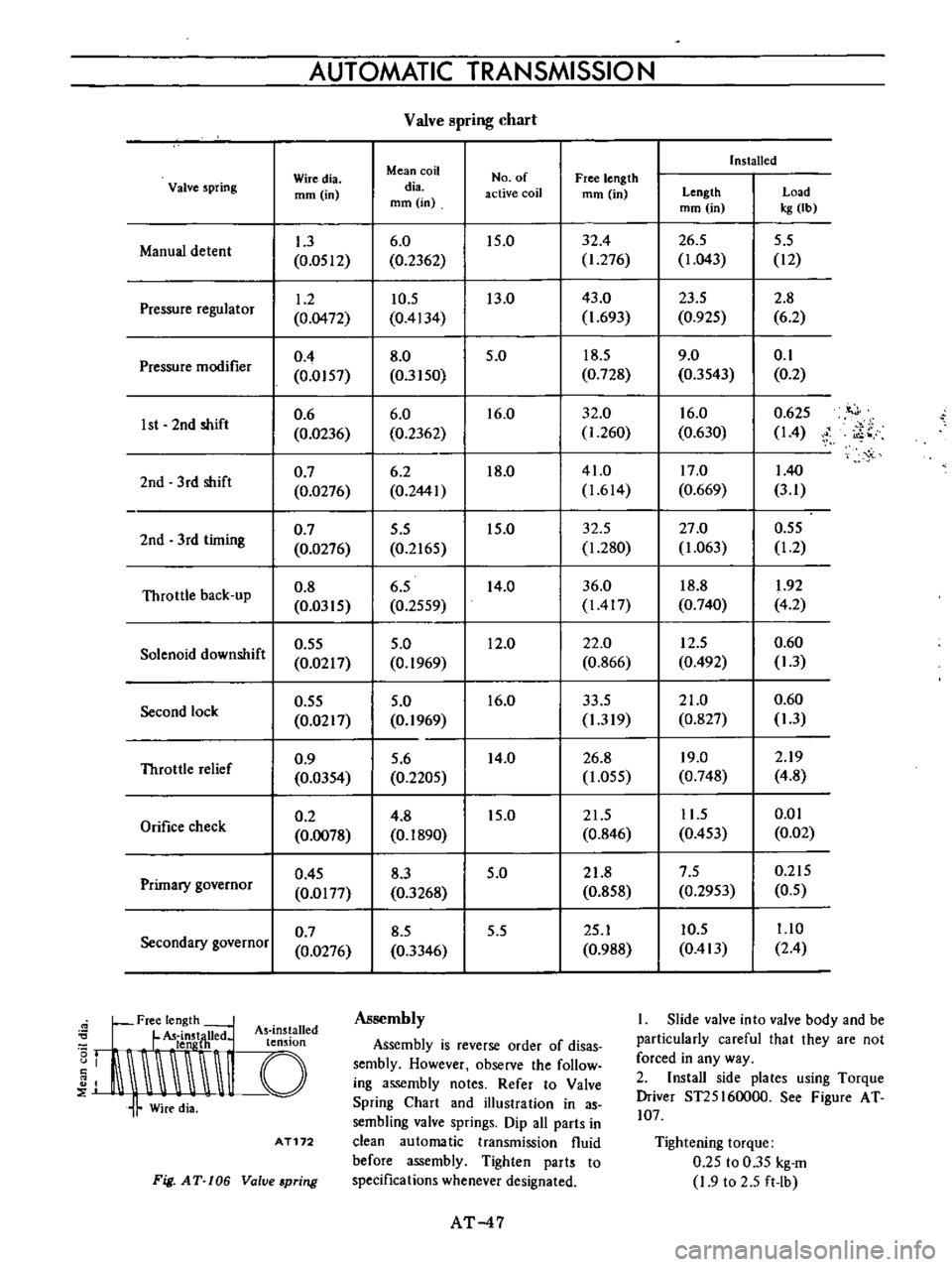
AUTOMATIC
TRANSMISSIO
N
Valve
pring
chart
Installed
Wiredia
Mean
coil
No
of
Free
length
Valve
spring
mm
in
dia
active
coil
mm
in
Length
Load
mm
in
mm
in
kg
Ib
1
3
6
0
15
0
32
4
26
5
5
5
Manual
detent
0
0512
0
2362
1
276
1
043
12
1
2
10
5
13
0
43
0
23
5
2
8
Pressure
regulator
0
0472
0
4134
1
693
0
925
6
2
0
4
8
0
5
0
18
5
9
0
0
1
Pressure
modifier
0
0157
0
3150
0
728
0
3543
0
2
0
6
6
0
16
0
32
0
16
0
0
625
it
J
1st
2nd
shift
0
0236
0
2362
1
260
0
630
14
i
o
0
7
6
2
18
0
41
0
17
0
140
2nd
3
rd
shift
0
0276
0
2441
1
614
0
669
3
1
0
7
5
5
15
0
32
5
27
0
0
55
2nd
3rd
timing
0
0276
0
2165
1
280
1
063
1
2
Throttle
back
up
0
8
6
5
14
0
36
0
18
8
1
92
0
0315
0
2559
1417
0
740
4
2
0
55
5
0
12
0
22
0
12
5
0
60
Solenoid
downshift
0
0217
0
1969
0
866
0
492
1
3
0
55
5
0
16
0
33
5
21
0
0
60
Second
lock
0
0217
0
1969
1
319
0
827
1
3
0
9
5
6
14
0
26
8
19
0
2
19
Throttle
relief
0
0354
0
2205
1
055
0
748
4
8
0
2
4
8
15
0
21
5
11
5
0
01
Orifice
check
0
0078
0
1890
0
846
0
453
0
02
0
45
8
3
5
0
21
8
7
5
0
215
Primary
governor
0
0177
0
3268
0
858
0
2953
0
5
0
7
8
5
5
5
25
1
10
5
1
10
Secondary
governor
0
0276
0
3346
0
988
0
413
2
4
Free
length
L
U
d
As
ins
alled
I
t
LldnstjH
e
t
n
Ion
J
I
I
Assembly
Assembly
is
reverse
order
of
disas
sembly
However
observe
the
follow
ing
assembly
notes
Refer
to
Valve
Spring
Chart
and
illustration
in
as
sembling
valve
springs
Dip
all
parts
in
clean
automatic
transmission
fluid
before
assembly
Tighten
parts
to
specifications
whenever
designated
AT172
Fig
AT
106
Value
pring
AT
47
I
Slide
valve
into
valve
body
and
be
particularly
careful
that
they
are
not
forced
in
any
way
2
Install
side
plates
using
Torque
Driver
ST25I60000
See
Figure
AT
107
Tightening
torque
0
25
to
0
35
kg
m
1
9
to
2
5
ft
Ib
Page 91 of 513
FRONT
AXLE
FRONT
SUSPENSION
Reinstalla
tion
First
check
rubber
parts
such
as
tension
rod
mount
ing
bushing
stabilizer
bar
bushing
etc
for
deterioration
crack
and
other
defective
conditions
and
replace
as
required
2
Reinstall
the
front
axle
and
suspension
assembly
in
reverse
sequence
of
removal
noting
the
following
matters
1
Tighten
the
transverse
link
mounting
bolts
and
stabilizer
bar
body
side
installation
bolt
to
the
raled
tightening
torque
under
the
unladen
vehicle
2
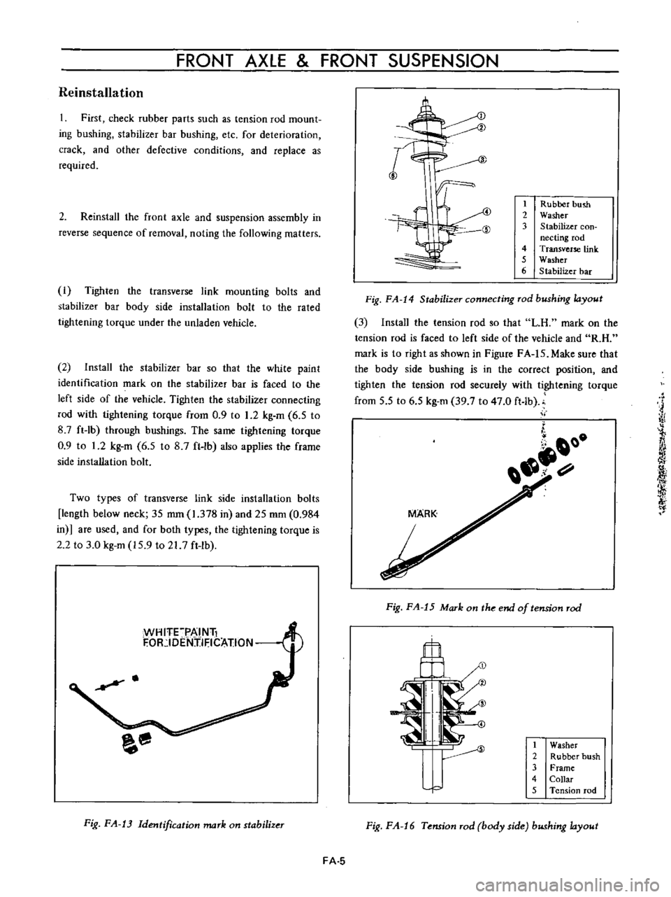
Install
the
stabilizer
bar
so
that
the
white
paint
identification
mark
on
the
stabilizer
bar
is
faced
to
the
left
side
of
the
vehicle
Tighten
the
stabilizer
connecting
rod
with
tightening
torque
from
0
9
to
1
2
kg
m
6
5
to
8
7
ft
lb
through
bushings
The
same
tightening
torque
0
9
to
1
2
kg
m
6
5
to
8
7
ft
Ib
also
applies
the
frame
side
installation
bolt
Two
types
of
transverse
link
side
installation
bolts
length
below
neck
35
mm
1
378
in
and
25
mm
0
984
in
are
used
and
for
both
types
the
tightening
torque
is
2
2
to
3
0
kg
m
15
9
to
217
ft
lb
WH
ITFPAI
Nli
F
OR
IDENjIFICATION
H
Fig
FA
13
Identification
mark
on
stabilizer
I
J
1
Rubber
hush
2
Washer
3
Stabilizer
con
necting
rod
4
Transverse
link
5
Washer
6
Stabilizer
bar
Fig
FA
14
Stabilizer
connecting
rod
bushing
layout
3
Install
the
tension
rod
so
that
LH
mark
on
the
tension
rod
is
faced
to
left
side
of
the
vehicle
and
R
H
mark
is
to
right
as
shown
in
Figure
FA
IS
Make
sure
that
the
body
side
bushing
is
in
the
correct
position
and
tighten
the
tension
rod
securely
with
tightening
torque
from
5
5
to
6
5
kg
m
39
7
to
47
0
ft
lb
ii
j
iY
l
fj
i
f
i
Of
1
0
Fig
FA
15
Mark
on
the
end
of
tension
rod
il
1
Washer
2
Rubber
bush
3
Frame
4
Collar
5
Tension
rod
Fig
FA
16
Tension
rod
body
side
bushing
layout
FA
5
Page 100 of 513
CHASSIS
Fig
FA
35
Removing
O
ring
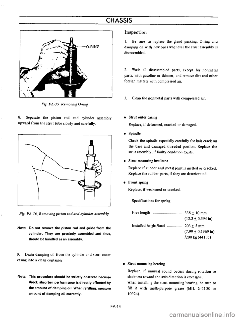
8
Separate
the
piston
rod
and
cyiinder
assembly
upward
from
the
strut
tube
slowly
and
carefully
M
Fig
FA
36
Removing
piston
rod
and
cylinder
assembly
Note
Do
not
remove
the
piston
rod
and
guide
from
the
cylinder
They
are
precisely
assembled
and
thus
should
be
handled
as
an
assembly
9
Drain
damping
oil
from
the
cylinder
and
strut
outer
casing
into
a
clean
container
Note
This
procedure
should
be
strictly
observed
because
shock
absorber
perlormance
is
directly
affected
by
the
amount
of
damping
oil
When
refilling
measure
amount
of
damping
oil
correctly
FA
14
Inspection
Be
sure
to
replace
the
gland
packing
O
ring
and
damping
oil
with
new
ones
whenever
the
strut
assetnb1y
is
disassembled
2
Wash
all
disassembled
parts
except
for
nonmetal
parts
with
gasoline
or
thinner
and
remove
dirt
and
other
foreign
matters
with
compressed
air
3
Clean
the
nonmetal
parts
with
compressed
air
Strut
outer
casing
Replace
if
deformed
cracked
or
damaged
Spindle
Check
the
spindle
especially
carefully
for
hair
crack
on
the
base
and
damaged
threaded
portion
Replace
the
strut
assembly
if
faulty
condition
exists
Strut
mounting
insulator
Replace
if
rubber
and
metal
joint
is
melted
or
cracked
Replace
the
rubber
parts
if
they
are
deteriorated
Front
spring
Replace
if
weakened
or
cracked
Specifications
for
spring
Free
length
338
t
10
mm
13
3
t
0
394
in
203
t
5
mm
7
99
t
0
1969
in
200
kg
441Ib
Installed
height
load
Strut
mounting
bearing
Replace
if
unusual
sound
occurs
during
rotation
or
slackness
toward
the
axis
direction
is
excessive
When
installing
the
strut
mounting
bearing
be
sure
to
fill
it
with
mul1i
purpose
grease
MIL
G
2108
or
10924
Page 102 of 513
CHASSIS
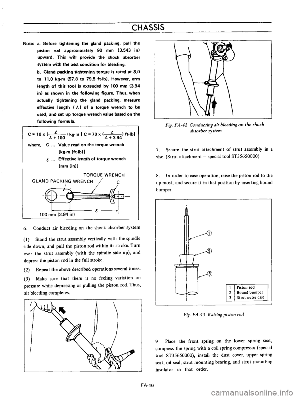
Note
a
Before
tightening
the
gland
packing
pull
the
piston
rod
approximately
90
mm
3
543
in
upward
This
will
provide
the
shock
absorber
system
with
the
best
condition
for
bleeding
b
Gland
packing
tightening
torque
is
rated
at
8
0
to
11
0
kg
m
57
8
to
79
5
ft
Ib
However
arm
length
of
this
tool
is
extended
by
100
mm
3
94
in
as
shown
in
the
following
figure
Thus
when
actually
tightening
the
gland
packing
measure
effective
length
L
of
a
torque
wrench
to
be
used
and
set
up
torque
wrench
value
based
on
the
following
formula
C
10
x
l
I
kg
m
C
70
x
l
I
ft
lbJ
100
l
3
94
where
C
Value
read
on
the
torque
wrench
kg
m
ft
lbIJ
Effective
length
of
torque
wrench
mm
in
l
TOROUE
WRENCH
GLAND
PACKING
WRENCH
I
C
4
F
r
I
L
I
100
mm
3
94
in
6
Conduct
air
bleeding
on
the
shock
absorber
system
1
Stand
the
strut
assembly
vertically
with
the
spindle
side
down
and
pull
the
piston
rod
within
its
stroke
Turn
over
the
strut
assembly
with
the
spindle
side
up
and
depress
the
piston
rod
in
the
full
stroke
2
Repeat
the
above
described
operations
several
times
3
Make
sure
that
there
is
no
feeling
variation
on
pressure
while
depressing
or
pulling
the
piston
rod
Thus
air
bleeding
completes
J
FA
16
Fig
FA
42
ConductingaiT
bleeding
on
the
shock
absorber
system
7
Secure
the
strut
attachment
of
strut
assembly
in
a
vise
Strut
attachment
special
tool
Sn5650000
8
In
order
to
ease
operation
raise
the
piston
rod
to
the
up
most
and
secure
it
in
that
position
by
inserting
bound
bum
per
t
D
I
T
I
c
I
Piston
rod
2
Bound
bumper
3
Strut
outer
case
Fig
FA
43
Raising
piston
rod
9
Place
the
front
spring
on
the
lower
spring
seat
compress
the
spring
with
a
coil
spring
compressor
special
tool
Sn5650000
install
the
dust
cover
upper
spring
seat
oil
seal
strut
mounting
bearing
and
strut
mounting
insulator
in
that
order
Page 106 of 513
CHASSIS
ST36721000
ST36722000
I
ST36723000
r
Fig
FA
53
Installing
transverse
link
bushing
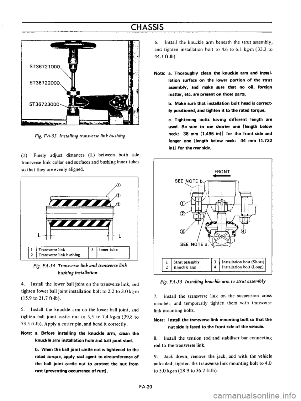
2
Finely
adjust
distances
L
between
both
side
transverse
link
collar
end
surfaces
and
bushing
inner
tubes
so
that
they
are
evenly
aligned
D
r
Ii
l
Ii
3
F
f
IIII
I
I
L
T
L
It
I
Transverse
link
2
Transverse
link
bushing
I
3
I
Inner
tube
Fig
FA
54
Transverse
link
and
transverse
link
bushing
nstal1o
tion
4
Install
the
lower
ball
joint
on
the
transverse
link
and
tighten
lower
ball
joint
installation
bolt
to
2
2
to
3
0
kg
m
159
to
21
7
ft
Ib
5
Install
the
knuckle
arm
on
the
lower
ball
joint
and
tighten
ball
joint
castle
nut
to
5
5
to
74
kg
m
39
8
to
53
5
ft
Ib
Apply
a
cotter
pin
and
bend
it
correctly
Note
3
Before
installing
the
knuckle
arm
clean
the
knuckle
arm
installation
hole
and
ball
joint
stud
b
When
the
ball
joint
castle
nut
is
tightened
to
the
rated
torque
apply
seal
agent
to
circumference
of
the
ball
joint
castle
nut
to
protect
the
nut
from
rust
preventing
occurrence
of
rust
FA
20
6
InstaIJ
the
knuckle
arm
beneath
the
strut
assembly
and
tighten
instaIJation
bolt
to
4
6
to
6
J
kg
m
33
3
to
44
I
ft
lb
Note
a
Thoroughly
clean
the
knuckle
arm
and
instal
lation
surface
on
the
lower
portion
of
the
strut
assembly
and
make
sure
that
no
oil
foreign
maner
etc
are
present
on
those
parts
b
Make
sure
that
installation
bolt
head
is
correct
ly
positioned
and
tighten
it
to
the
rated
torque
c
Tightening
bolu
having
different
length
are
used
Be
sure
to
use
shorter
one
length
below
neck
38
mm
11496
in
for
the
front
side
and
longer
one
length
below
neck
44
mm
1
132
in
for
the
rear
side
FRONT
II
I
Strut
assembly
2
Knuckle
arm
143
I
Installation
bolt
Short
I
Installation
bolt
Long
Fig
FA
55
Installing
knuckle
ann
to
strut
assembly
7
I
nstall
the
transverse
link
on
the
suspension
cross
member
and
temporarily
tighten
them
with
transverse
link
mounting
bolts
Note
Install
the
transverse
link
mounting
bolt
so
that
the
nut
side
is
faced
to
the
front
side
of
the
vehicle
8
Install
the
tension
rod
and
stabilizer
bar
connecting
rod
to
the
transverse
link
9
Jack
down
remove
the
jack
and
with
the
vehicle
unloaded
tighten
the
transverse
link
mounting
bolt
to
4
0
to
5
0
kg
m
28
9
to
36
2
ft
lb
Page 109 of 513
FRONT
AXLE
FRONT
SUSPENSION
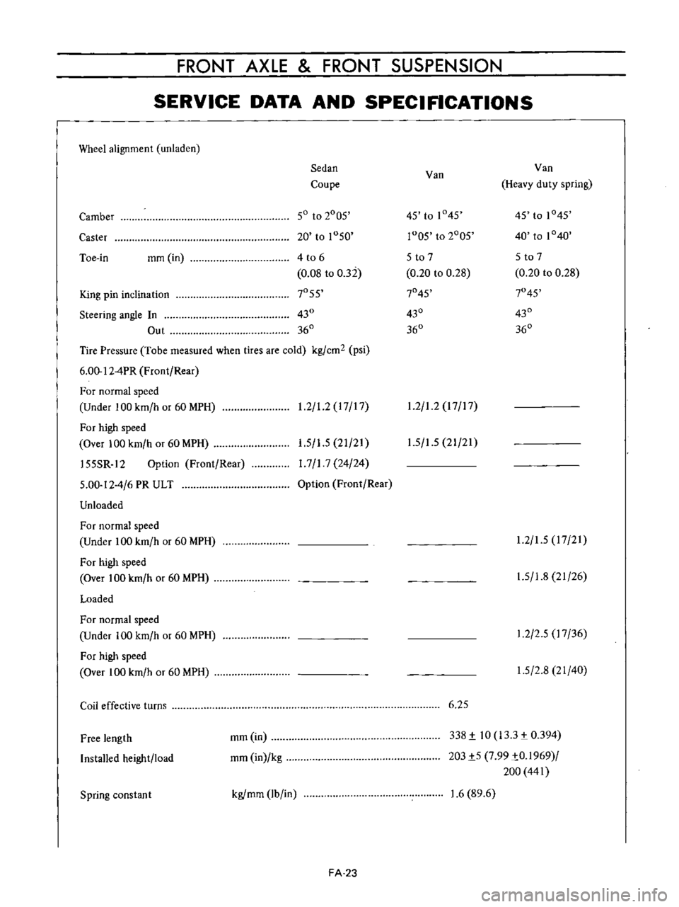
SERVICE
DATA
AND
SPECIFICATIONS
Wheel
alignment
unladen
Sedan
Van
Van
Coupe
Heavy
duty
spring
Camber
50
to
2005
45
to
1
45
45
to
1045
Caster
20
to
1050
r005
to
2005
40
to
1040
Toe
in
mm
in
4
t06
5
to
7
5
to
7
0
08
to
032
0
20
to
0
28
0
20
to
0
28
King
pin
inclination
7055
7045
7045
Steering
angle
In
430
430
430
Out
360
360
360
Tire
Pressure
Tobe
measured
when
tires
are
cold
kg
cm2
psi
6
00
12
4PR
Front
Rear
For
normal
speed
Under
100
km
h
or
60
MPH
1
2
1
2
17
17
1
2
1
2
17
17
For
high
speed
Over
100
km
h
or
60
MPH
155SR
12
Option
Front
Rear
5
00
12
4
6
PR
ULT
Unloaded
1
5
1
5
21
21
1
7
1
7
24
24
Option
Front
Rear
1
5
1
5
21
21
For
normal
speed
Under
100
km
h
or
60
MPH
For
high
speed
Over
100
km
h
or
60
MPH
Loaded
1
2
1
5
17
21
1
5
1
8
21
26
For
normal
speed
Under
100
km
h
or
60
MPH
For
high
speed
Over
100
km
h
or
60
MPH
1
2
2
5
17
36
1
5
2
8
21
40
Coil
effective
turns
6
25
Free
length
Installed
height
load
mm
in
mm
in
kg
338
i
10
133
0394
203i5
7
99
iO
1969
200
441
Spring
constan
t
kgfmm
lb
in
1
6
89
6
FA
23
Page 122 of 513
REAR
AXLE
REAR
SUSPENSION
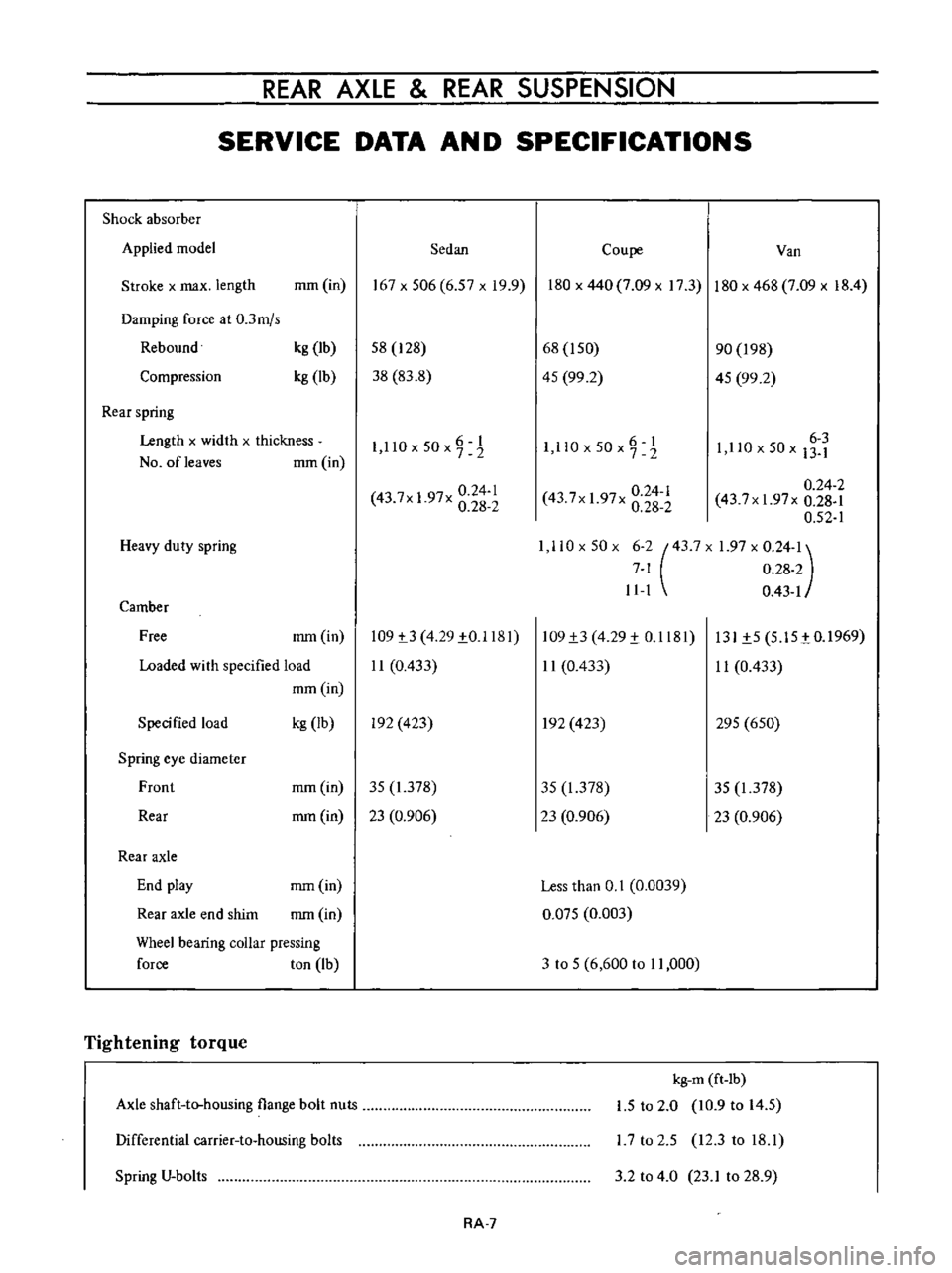
SERVICE
DATA
AN
D
SPECIFICATIONS
Shock
absorber
Applied
model
Sedan
Coupe
Van
Stroke
x
max
length
mm
in
167x506
6
57xI9
9
180
x
440
7
09
x
17
3
180
x
468
7
09
x
18
4
Damping
force
at
0
3mjs
Rebound
Compression
kg
Ib
kg
lb
58
128
38
83
8
68
I
50
45
99
2
90
198
45
99
2
Rear
spring
Length
x
widlh
x
thickness
NO
ofleaves
mm
in
6
I
1
llOx50x72
O
6
1
I
ll
x50x7
2
6
3
1
110
x
50
x
13
1
0
24
1
43
7x
1
97x
0
28
2
0
24
2
43
7xI
97x
0
28
1
0
52
1
1
110x50x
6
2
43
7X
1
97
x
0
24
1
7
1
0
28
2
11
1
0
43
1
0
24
1
43
7x
1
97x
0
28
2
Heavy
duty
spring
Camber
Free
mm
in
109
t3
4
29
1
0
1181
11
0
433
109
1
3
4
29
1
0
1181
11
0
433
131
1
5
5
15
tO
1969
11
0
433
Loaded
wi
th
specified
load
mm
in
Specified
load
kg
Ib
In
423
In
423
295
650
Spring
eye
diameter
Front
mm
in
35
1
378
35
1
378
35
1
378
Rear
mm
in
23
0
906
23
0
906
23
0
906
Rear
axle
End
play
mm
in
Less
than
0
1
0
0039
Rear
axle
end
shim
mm
in
0
Q75
0
003
Wheel
bearing
coUar
pressing
force
ton
Ib
3
to
5
6
600
to
11
000
Tightening
torque
Axle
shaft
to
housing
flange
bolt
nuts
kg
m
ft
lb
1
5
to
2
0
10
9
to
14
5
L7
to
2
5
12
3
to
18
1
Differential
carrier
to
housing
bolts
Spring
V
bolts
3
2
to
4
0
23
1
to
28
9
RA
7