1973 DATSUN B110 length
[x] Cancel search: lengthPage 133 of 513
7
Remove
the
brake
disc
installation
bolt
and
remove
the
brake
disc
from
the
spindle
8
Disassemble
the
wheel
cylinders
Inspection
l
Drums
If
they
show
score
excessive
out
of
round
and
so
forth
reconditioning
by
machining
is
required
Brake
drum
inner
diameter
203
2
mm
8
00
in
Drum
inside
out
of
roundness
Below
0
02
mm
0
0008
in
Max
allowable
drum
inner
diameter
204
5
mm
8
051
in
2
Linings
If
brake
shoe
linings
are
incomp1etedly
seated
soiled
or
greasy
or
deteriorated
due
to
excessive
heating
repair
or
replace
them
If
the
thickness
of
the
lining
is
less
than
1
5
mm
0
0591
in
replace
it
Note
a
If
oil
or
grease
is
found
on
linings
clean
thoroughly
with
carbon
tetrachloride
or
gasoline
b
After
installing
and
bonding
lining
grind
the
lining
face
to
a
diameter
equal
to
the
brake
drum
3
Check
the
adjusting
cams
for
their
smooth
operation
4
Return
springs
If
they
are
considerably
weak
replace
them
Return
spring
dimension
Wire
diameter
x
free
length
turns
3
2
x
118
mm
20
5
0
1260
x
4
65
in
20
5
Load
x
length
55
kg
I21
lb
x
127
1
mm
5
00
in
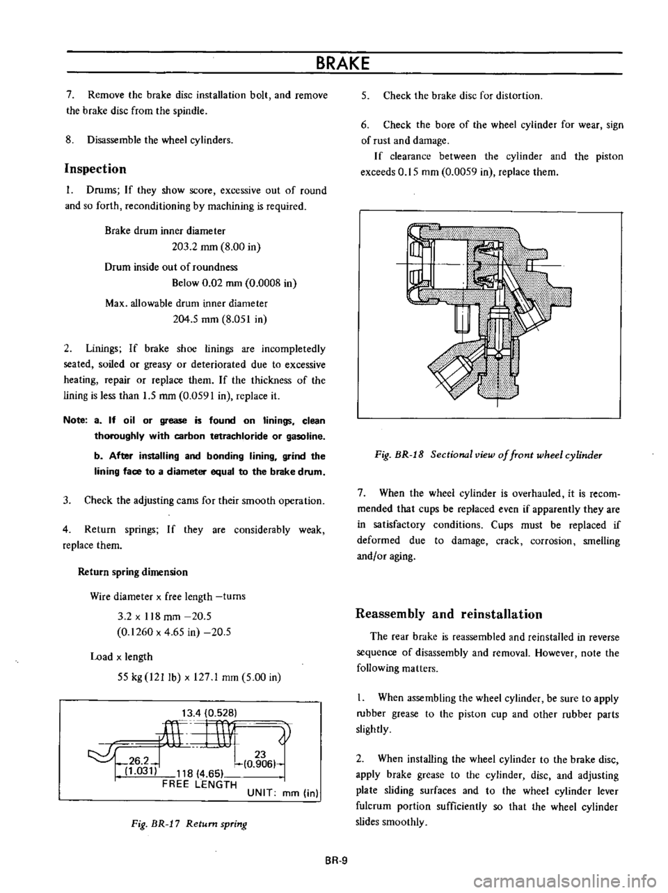
13
4
0
528
ilL
rnv
0
t
6
hl
03
118
4
65
FREE
LENGTH
UNIT
mm
in
Fig
BR
J
7
Return
spring
BRAKE
5
Check
the
brake
disc
for
distortion
6
Check
the
bore
of
the
wheel
cylinder
for
wear
sign
of
rust
and
damage
If
clearance
between
the
cylinder
and
the
piston
exceeds
0
15
mm
0
0059
in
replace
them
Fig
BR
J
8
Sectional
view
of
front
wheel
cylinder
7
When
the
wheel
cylinder
is
overhauled
it
is
recom
mended
that
cups
be
replaced
even
if
apparently
they
are
in
satisfactory
conditions
Cups
must
be
replaced
if
deformed
due
to
damage
crack
corrosion
smelling
andf
or
aging
Reassembly
and
reinstallation
The
rear
brake
is
reassembled
and
reinstalled
in
reverse
sequence
of
disassembly
and
removal
However
note
the
following
matters
When
assembling
the
wheel
cylinder
be
sure
to
apply
rubber
grease
to
the
piston
cup
and
other
rubber
parts
slightly
2
When
installing
the
wheel
cylinder
to
the
brake
disc
apply
brake
grease
to
the
cylinder
disc
and
adjusting
plate
sliding
surfaces
and
to
the
wheel
cylinder
lever
fulcrum
portion
sufficiently
so
that
the
wheel
cylinder
slides
smoothly
BR
9
Page 141 of 513
BRAKE
Removal
and
disassembly
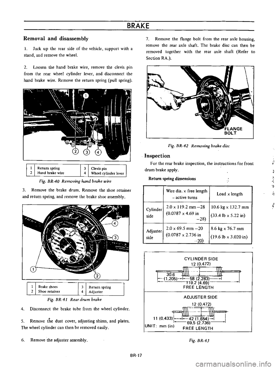
1
Jack
up
the
rear
side
of
the
vehicle
support
with
a
stand
and
remove
the
wheeL
2
Loosen
the
hand
brake
wire
remove
the
clevis
pin
from
the
rear
wheel
cylinder
lever
and
disconnect
the
hand
brake
wire
Remove
the
return
spring
pull
spring
I
I
k
re
I
I
l
nlinder
lever
I
Fig
BR
40
Removing
hand
brake
wire
3
Remove
the
brake
drum
Remove
the
shoe
retainer
and
return
spring
and
remove
the
brake
shoe
assembly
I
I
I
I
Brake
shoes
Shoe
retainer
Return
spring
Adjuster
Fig
BR
41
Rear
drum
brake
4
Disconnect
the
brake
tube
from
the
wheel
cylinder
5
Remove
the
dust
cover
adjusting
shims
and
plates
The
wheel
cylinder
can
then
be
removed
easily
6
Remove
the
adjuster
assembly
7
Remove
the
flange
bolt
from
the
rear
axle
housing
remove
the
rear
axle
shaft
The
brake
disc
can
then
be
removed
together
with
the
rear
axie
shaft
Refer
to
Section
RA
Fig
BR
42
Removing
brake
disc
Inspection
For
the
rear
brake
inspection
the
instructions
for
front
drum
brake
apply
Return
spring
dimensions
Wire
dia
x
free
length
active
turns
Load
x
length
Cylinder
side
2
0
x
119
2
mm
28
0
0787
x
4
69
in
28
10
6
kg
x
132
7
mm
33
4lb
x
5
22
in
Adjuster
side
2
0
x
69
5
mm
20
0
0787
x
2
736
in
20
8
6
kg
x
76
7
mm
I9
6lb
d
020
in
CYLINDER
SIDE
t
2
0
472
r
lif
r
1
5
58
2
283F
119
2
4
69
FREE
LENGTH
ADJUSTER
SIDE
1210
472
11
0
433
J54J
69
5
2
736
FREE
LENGTH
UNIT
mm
in
Fig
BR
43
BR
17
Page 147 of 513
BRAKE
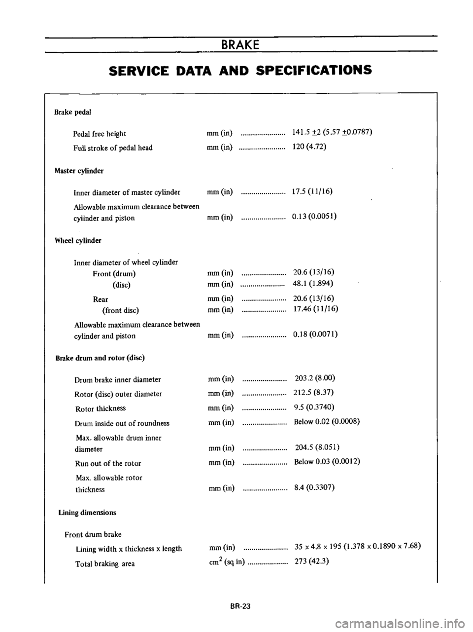
SERVICE
DATA
AND
SPECIFICATIONS
Brake
pedal
Pedal
free
height
Full
stroke
of
pedal
head
Master
cylinder
mm
in
mm
in
141
5
t2
5
57
to
0787
120
4
72
17
5
11
16
Inner
diameter
of
master
cylinder
mm
in
Allowable
maximum
clearance
between
cylinder
and
piston
mm
in
Wheel
cylinder
Inner
diameter
of
wheel
cylinder
Front
drum
disc
Rear
front
disc
Allowable
maximum
clearance
between
cylinder
and
piston
Brake
drum
and
rotor
disc
Drum
brake
inner
diameter
Rotor
disc
outer
diameter
Rotor
thickness
Drum
inside
out
of
roundness
Max
allowable
drum
inner
diameter
Run
out
of
the
rotor
Max
allowable
rotor
thickness
Lining
dimensions
Front
drum
brake
Lining
width
x
thickness
x
length
Total
braking
area
0
13
0
0051
mm
in
mm
in
mm
in
mm
in
20
6
13
16
48
1
1
894
20
6
13
16
1746
11
16
mm
in
0
18
0
0071
mm
in
mm
in
mm
in
mm
in
203
2
8
00
212
5
837
9
5
03740
Below
0
Q2
0
0008
mm
in
mm
in
204
5
8
051
Below
0
03
0
0012
mm
in
8
4
03307
mm
in
cm2
sq
in
35
x
4
8
x
195
1
378
x
0
1890
x
7
68
273
423
BR
2J
Page 148 of 513
Lining
material
Front
disc
brake
Pad
width
x
thickness
x
length
Total
braking
area
Rear
brake
Lining
width
x
thickness
x
length
Total
braking
area
Tightening
torque
Brake
pedal
fulcrum
pin
Master
cylinder
installation
bolt
Brake
tube
installation
flare
nut
Rear
brake
hose
and
connector
installation
nut
Front
wheel
cylinder
installation
bolt
Brake
warning
switch
installation
bolt
Front
brake
disc
installation
bolt
Caliper
assembly
installation
bolt
Rear
brake
adjuster
installation
bolt
Hand
brake
cable
hanger
strap
installation
bolt
Hand
brake
lever
installation
bolt
Rotor
and
hub
installation
bolt
CHASSIS
mm
in
cm2
sq
in
mm
in
cm2
sq
in
kg
m
ft
1b
kg
m
ft
lb
kg
m
ft
lb
kg
m
ft
lb
kg
m
ft
lb
kg
m
ft
lb
kg
m
ft
lb
kg
m
ft
lb
kg
m
ft
lb
kg
m
ft
lb
kg
m
ft
lb
kg
m
ft
Ib
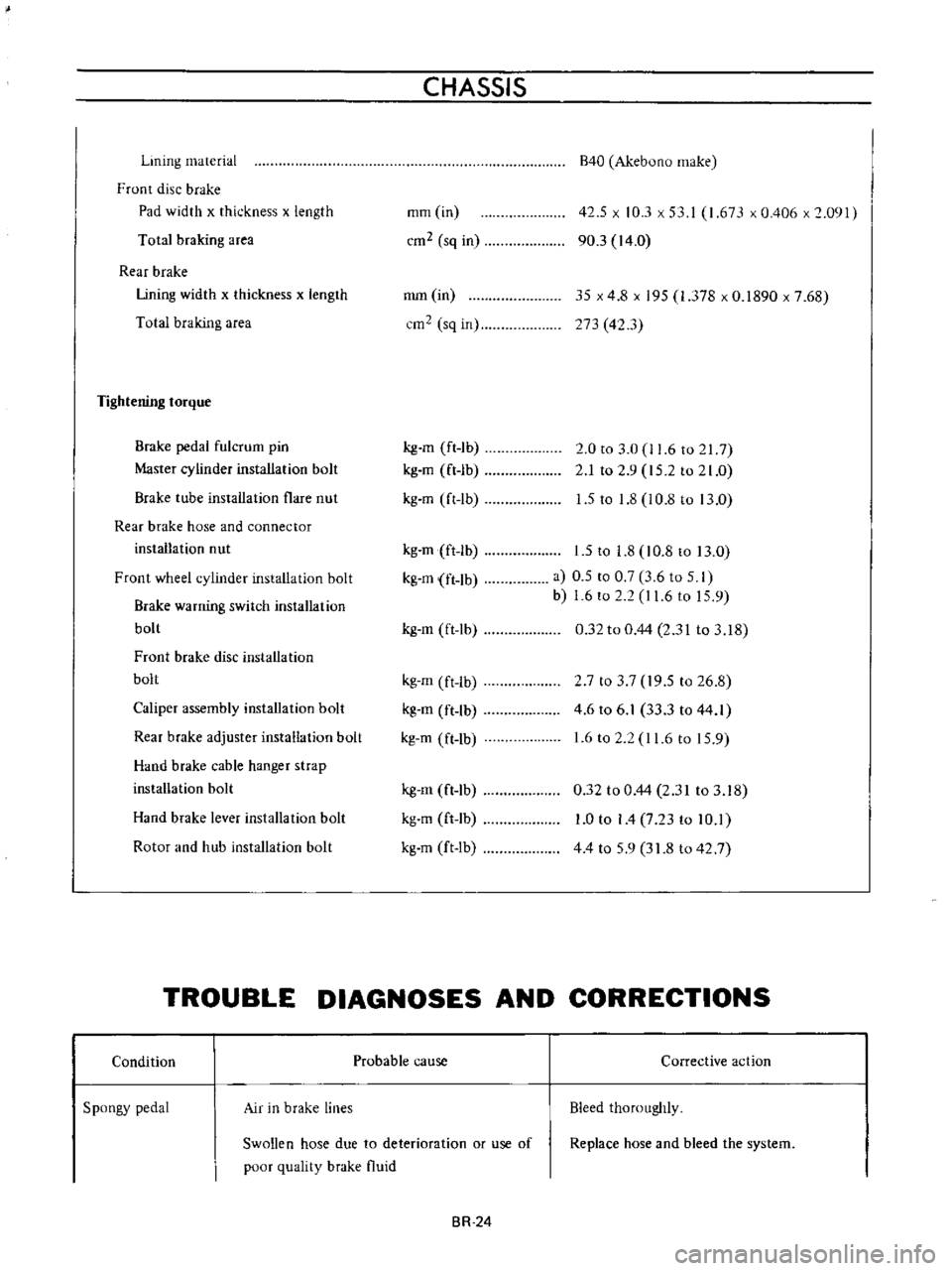
B40
Akebuno
make
42
5
x
10
3
x
53
I
1
673
x
0
406
x
2
091
90
3
14
0
35
x
4
8
x
195
1
378
x
0
1890
x
7
68
273
42
3
2
0
to
3
0
11
6
to
217
2
1
to
2
9
15
2
to
21
0
1
5
to
1
8
l
0
8
to
13
0
1
5
to
1
8
10
8
to
13
0
a
0
5
to
0
7
3
6
to
5
I
b
1
6
to
2
2
I
1
6
to
15
9
0
32
to
0
44
2
31
to
3
18
2
7
to
3
7
19
5
to
26
8
4
6
to
6
1
33
3
to
44
1
1
6
to
2
2
11
6
to
15
9
0
32
to
0
44
2
31
to
3
18
1
0
to
I
4
7
23
to
10
1
44
to
59
31
8
to
42
7
TROUBLE
DIAGNOSES
AND
CORRECTIONS
Condition
Spongy
pedal
Air
in
brake
lines
Probable
cause
Swollen
hose
due
to
deterioration
or
use
of
poor
quality
brake
fluid
BR
24
Corrective
action
Bleed
thoroughly
Replace
hose
and
bleed
the
system
Page 171 of 513
STEERING
The
jacket
tube
is
of
a
mesh
and
a
part
of
which
is
punched
in
rhombus
forming
an
energy
absorbing
part
of
the
collapsible
steering
Upper
and
lower
guide
tubes
two
guide
tubes
joined
with
polyacetal
resin
are
inserted
into
the
mesh
tube
so
STEERING
POST
CLAMP
that
an
energy
generated
by
collision
can
be
absorbed
as
smoothly
as
possible
with
a
low
load
The
guide
tubes
function
as
a
guide
for
mesh
tube
while
the
mesh
tube
is
collapsed
and
improve
bending
rigidity
of
the
entire
jacket
tube
1
1
Plastic
pin
I
2
I
Clamp
1
3
I
Sliding
block
Fig
ST
19
Steering
post
clamp
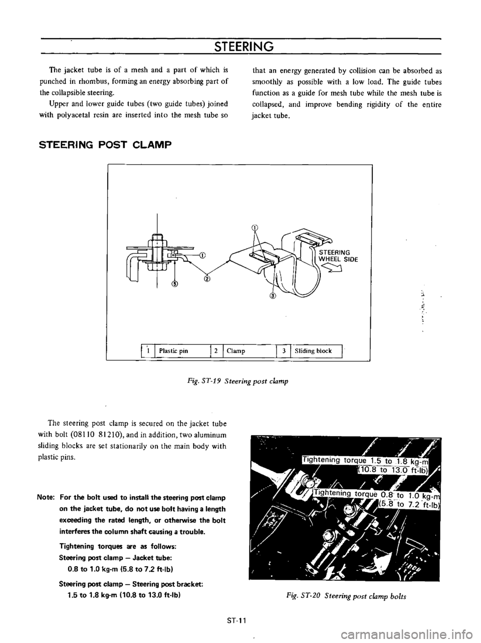
The
steering
post
clamp
is
secured
on
the
jacket
tube
with
bolt
08110
81210
and
in
addition
two
aluminum
sliding
blocks
are
set
stationarity
on
the
main
body
with
plastic
pins
Note
For
the
bolt
used
to
install
the
steering
post
clamp
on
the
jacket
tube
do
not
use
bolt
having
a
length
exceeding
the
rated
length
or
otherwise
the
bolt
interferes
the
column
shaft
causing
a
trouble
Tightening
torques
are
as
follows
Steering
post
clamp
Jacket
tube
0
8
to
1
0
kg
m
5
8
to
7
2
ft
lb
Steering
post
clamp
Steering
post
bracket
1
5
to
1
8
kg
m
10
8
to
13
0
ft
Ib
Fig
ST
20
Steering
post
clamp
bolts
ST
11
Page 172 of 513
CHASSIS
The
sliding
block
is
secured
on
the
steering
post
bracket
with
bolts
upper
half
of
the
steering
column
is
supported
on
the
bracket
and
thus
the
steering
post
clamp
is
installed
on
the
body
When
a
large
impact
is
applied
from
the
driver
side
the
plastic
pins
are
cut
off
and
leaving
the
sliding
block
in
the
steering
post
bracket
side
the
clamp
proper
is
disengaged
downward
together
with
the
jacket
tube
For
any
force
applied
from
front
direction
of
the
vehicle
the
steering
post
clamp
sliding
block
does
not
move
rearward
This
construction
is
called
One
way
slide
system
and
with
this
construction
projection
of
the
column
shaft
toward
the
driver
is
prevented
completely
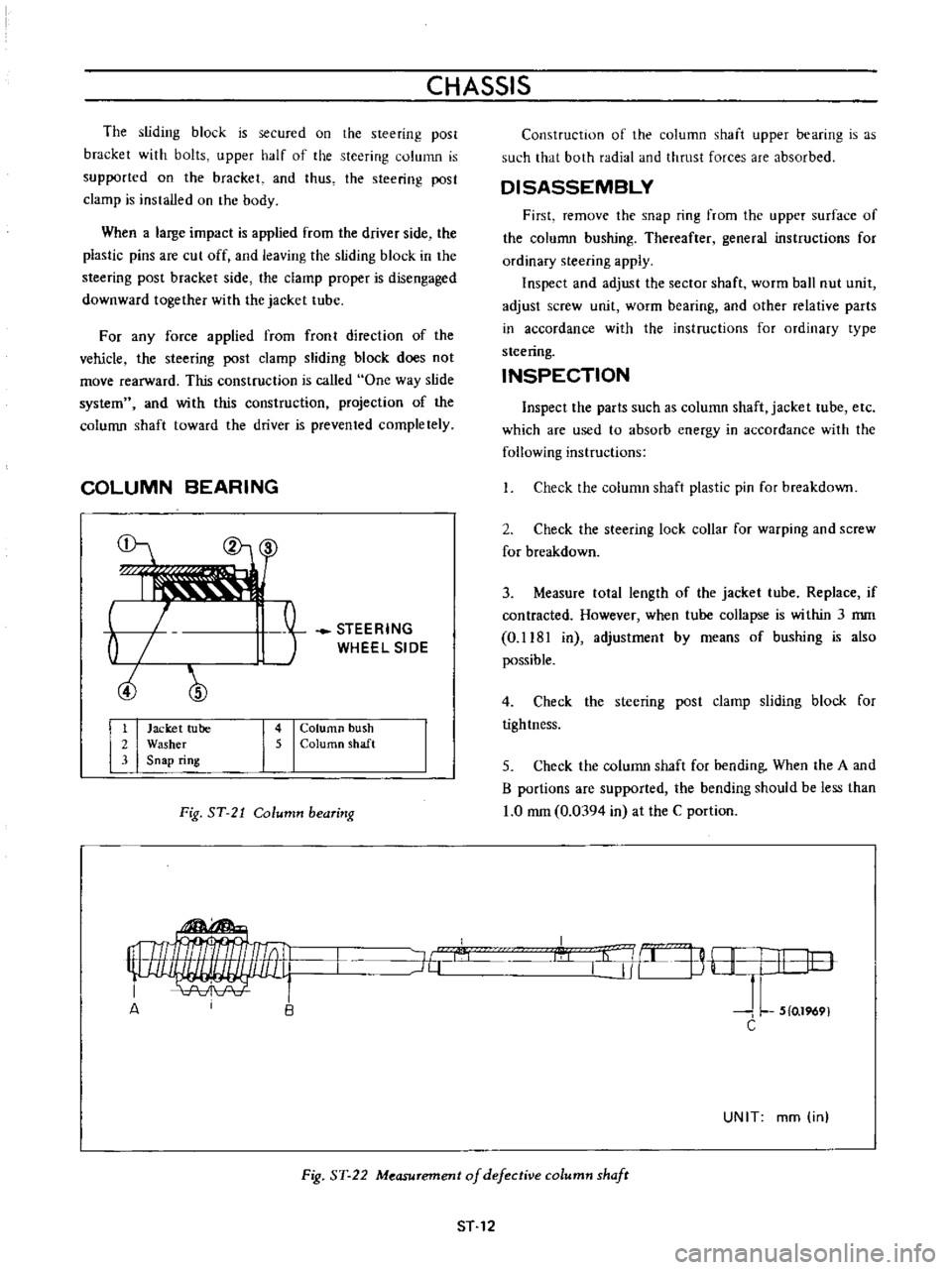
COLUMN
BEARING
b
ciJ
STEERING
WHEEL
SIDE
1
Jacket
tube
2
Washer
3
Snap
ring
4
Column
bush
5
ColurtlO
shaft
Fig
ST
21
Column
bearing
Construction
of
the
column
shaft
upper
bearing
is
as
such
that
both
radial
and
thrust
forces
are
absorbed
DISASSEMBLY
First
remove
the
snap
ring
from
the
upper
surface
of
the
column
bushing
Thereafter
general
instructions
for
ordinary
steering
apply
Inspect
and
adjust
the
sector
shaft
worm
ball
nut
unit
adjust
screw
unit
worm
bearing
and
other
relative
parts
in
accordance
with
the
instructions
for
ordinary
type
steering
INSPECTION
Inspect
the
parts
such
as
column
shaft
jacket
tube
etc
which
are
used
to
absorb
energy
in
accordance
with
the
following
instructions
Check
the
column
shaft
plastic
pin
for
breakdown
2
Check
the
steering
lock
collar
for
warping
and
screw
for
breakdown
3
Measure
tolal
length
of
the
jacket
tube
Replace
if
contracted
However
when
tube
collapse
is
within
3
mm
0
1181
in
adjustmenl
by
means
of
bushing
is
also
possible
4
Check
the
steering
post
clamp
sliding
block
for
tightness
5
Check
the
column
shaft
for
bending
When
the
A
and
B
portions
are
supported
the
bending
should
be
less
than
1
0
mm
0
0394
in
at
the
C
portion
I
l
j
B
H
I
I
lO
J
L
5
0
1969
C
J6
A
UNIT
mm
in
Fig
ST
22
Measurement
of
defective
column
shafr
ST
12
Page 173 of 513
STEERING
REASSEMBLY
Adjust
alignment
and
install
the
worm
shaft
and
jacket
tube
on
the
housing
2
Apply
bearing
grease
to
the
interior
sufficiently
and
screw
the
column
bushing
above
the
rated
position
3
Apply
washer
and
apply
the
snap
ring
to
the
groove
correctly
and
securely
4
Return
the
column
bushing
allowing
the
top
surface
of
the
bushing
coming
into
contact
wi
th
the
lower
surface
of
the
washer
adjust
the
clearance
to
less
than
1
0
mm
0
0394
in
and
adjust
the
bushing
position
correctly
so
that
column
shaft
turning
torque
is
the
rated
value
Note
If
the
clearance
is
too
small
the
steering
becomes
heavy
5
Line
up
the
jacket
tube
upper
end
to
the
groove
on
the
outer
circumference
of
the
column
bushing
and
securely
caulk
two
symmetrical
positions
on
the
circum
ference
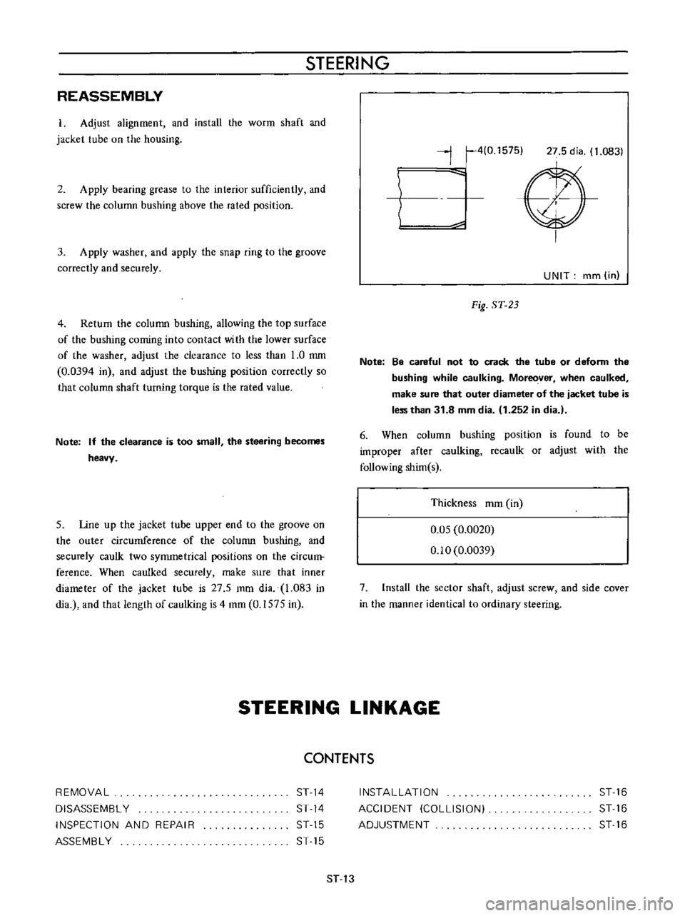
When
caulked
securely
make
sure
that
inner
diameter
of
the
jacket
tube
is
27
5
mm
dia
1
083
in
dia
and
that
length
of
caulking
is
4
mm
0
1575
in
j
410
1575
27
5
dia
1
0831
V
UNIT
mm
in
Fig
ST
23
Note
Be
careful
not
to
crack
the
tube
or
deform
the
bushing
while
caulking
Moreover
when
caulked
make
sure
that
outer
diameter
of
the
jacket
tube
is
less
than
31
8
mm
dia
1
252
in
dia
6
When
column
bushing
position
is
found
to
be
improper
after
caulking
recaulk
or
adjust
with
the
following
shim
s
Thickness
mm
in
0
05
0
0020
0
10
0
0039
7
Install
the
sector
shaft
adjust
screw
and
side
cover
in
the
manner
identical
to
ordinary
steering
STEERING
LINKAGE
CONTENTS
REMOVAL
DISASSEMBl
Y
INSPECTION
AND
REPAIR
ASSEMBl
Y
ST
14
ST
14
ST
15
ST
15
INSTAllATION
ACCIDENT
COLLISION
ADJUSTMENT
ST
16
ST
16
ST
16
ST
13
Page 176 of 513
CHASSIS
The
following
tightening
torque
of
nuts
shall
be
adopted
Ball
stud
nut
3
0
to
5
0
kg
m
21
7
to
36
2
ft
lb
Gear
arm
nut
14
kg
m
101
ft
lb
Idler
arm
nut
57
to
6
3
kg
m
41
2
to
45
6
ft
lb
2
Assembly
of
the
idler
assembly
is
accomplished
as
follows
I
Apply
soap
water
on
the
outer
circumference
of
bushing
Press
the
bushing
into
the
idler
arm
carefully
until
the
bushing
protrudes
equally
at
the
both
sides
2
Fit
idler
arm
body
in
the
rubber
bushing
Keep
the
idler
arm
center
line
in
parallel
with
the
chassis
center
line
INSTALLATION
Installation
can
be
accomplished
in
the
reverse
order
of
removal
Pay
attention
to
the
following
points
Set
the
length
of
both
side
rods
to
296
8
mm
11
69
in
It
should
be
done
between
the
ball
stud
centers
2
Check
wheel
alignment
and
if
necessary
adjust
it
ACCIDENT
COLLISION
When
accident
collision
occurs
unfortunately
and
the
vehicle
especially
its
front
unit
is
damaged
conduct
inspection
in
accordance
with
the
following
instruction
Inspect
the
steering
system
particularly
carefully
because
it
is
a
very
important
unit
for
driving
I
Check
both
side
steering
angles
for
correct
balance
2
With
the
tires
positioned
at
neutral
steering
wheel
bar
for
correct
position
check
the
l
3
Operate
the
steering
system
and
check
it
for
sliding
noise
4
Check
the
operation
for
smoothness
l
5
Check
the
side
rod
and
cross
rod
for
bending
6
Check
the
gear
arm
for
crack
7
Check
the
gear
housing
tiglltening
bolt
for
slackness
and
installation
boss
for
crack
8
Check
the
sector
shaft
serration
for
twisting
9
Check
the
sector
gear
for
crack
10
Check
the
ball
screw
for
pitting
II
Check
the
column
shaft
for
bending
crack
and
sliding
scar
12
Check
the
jacket
tube
for
bending
13
Check
the
steering
post
clamp
for
existance
of
column
offset
14
Check
the
side
member
gear
housing
installation
unit
for
deformation
IS
Check
the
portion
of
the
steering
post
bracket
installed
on
the
steering
post
clamp
for
correct
installation
AD
JUSTMENT
I
Toe
in
The
procedure
of
toe
in
adjustment
is
outlined
in
section
FRONT
AXLE
AND
FRONT
SUSPENSION
2
Steering
angle
Under
the
specified
load
4
passengers
adjust
the
stopper
bolt
of
the
knuckle
arm
so
that
the
inner
wheel
has
an
angle
of
430
Note
Specified
steering
angle
of
wheel
is
430
for
inner
wheel
and
36005
for
outer
wheel
ST
16