1973 DATSUN B110 alternator
[x] Cancel search: alternatorPage 241 of 513
INSPECTION
Referring
to
the
wiring
diagram
check
the
wiring
harness
for
connection
with
electrical
equipment
and
connector
for
conned
ion
and
installation
When
checking
the
wiring
harness
note
the
following
matters
Connected
unit
should
not
be
loose
rusted
or
contaminated
2
Cable
insulator
cover
should
not
be
damaged
crack
ed
or
insulating
material
should
not
be
deteriorated
3
For
those
parts
which
are
grounded
through
the
installation
bolts
the
bolts
should
be
in
contact
with
the
body
completely
so
that
continuity
is
provided
in
between
the
body
and
bolts
4
Terminals
of
unit
through
which
current
flows
should
not
come
into
contact
with
other
metal
parts
5
No
erroneous
connection
should
be
present
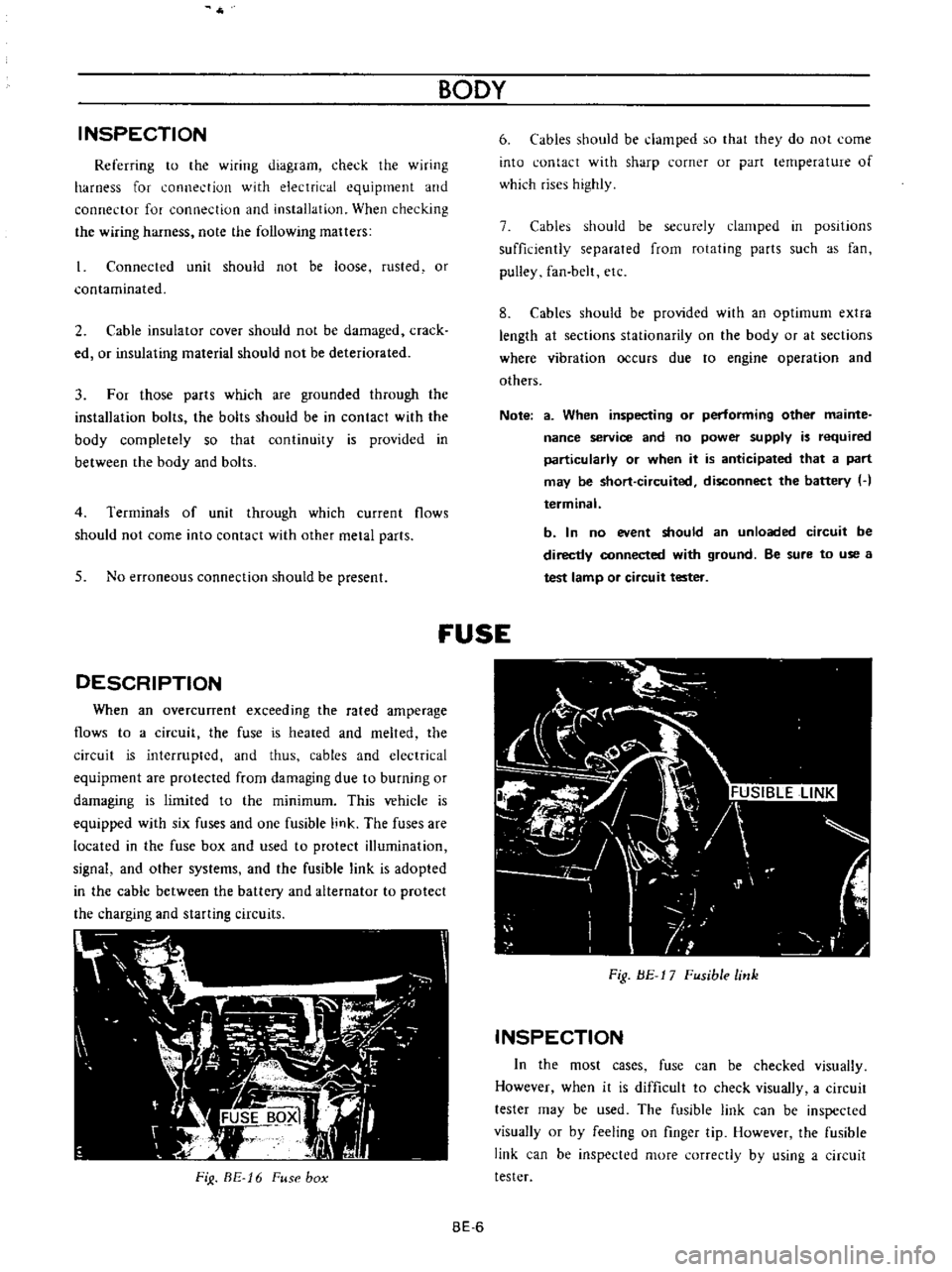
DESCRIPTION
When
an
overcunent
exceeding
the
rated
amperage
flows
to
a
circuit
the
fuse
is
heated
and
melted
the
circuit
is
interrupted
and
thus
cables
and
electrical
equipment
are
protected
from
damaging
due
to
burning
or
damaging
is
limited
to
the
minimum
This
vehicle
is
equipped
with
six
fuses
and
one
fusible
link
The
fuses
are
located
in
the
fuse
box
and
used
to
protect
illumination
signal
and
other
systems
and
the
fusible
link
is
adopted
in
the
cable
between
the
battery
and
alternator
to
protect
the
charging
and
starting
circuits
FiJ
BE
16
Fuse
box
BODY
6
Cables
should
be
damped
so
that
they
do
not
come
into
contact
with
sharp
corner
or
part
lernperature
of
which
rises
highly
7
Cables
should
be
securely
clamped
in
posItions
sufficiently
separated
from
rotating
parts
such
as
fan
pulley
fan
belt
etc
8
Cables
should
be
provided
with
an
optimum
extra
length
at
sections
stationarity
on
the
body
or
at
sections
where
vibration
occurs
due
to
engine
operation
and
others
Note
a
When
inspecting
or
performing
other
mainte
nance
service
and
no
power
supply
is
required
particularly
or
when
it
is
anticipated
that
a
part
may
be
short
circuited
disconnect
the
battery
H
terminal
b
In
no
event
should
an
unloaded
circuit
be
directly
connected
with
ground
Be
sure
to
use
a
test
lamp
or
circuit
tester
fUSE
Fig
BE
17
Fusible
link
INSPECTION
In
the
most
cases
fuse
can
be
checked
visually
However
when
it
is
difficult
to
check
visually
a
circuit
tester
may
be
used
The
fusible
link
can
be
inspected
visually
or
by
feeling
on
finger
tip
However
the
fusible
link
can
be
inspected
more
correctly
by
using
a
circuit
tester
BE
6
Page 251 of 513
9HORN
r
I
01
8ATTERY
HI
IGI
s
ILl
C
iORN
BODY
FUSE
H
S
HORN
BUTTON
BGI
J
H
B
S
Il
I
n6lm
I
L
J
L
HORN
RELAY
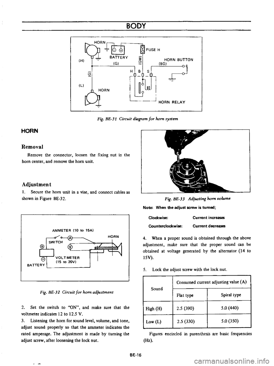
Fig
BE
3l
Circuit
diagram
for
hom
syrtem
HORN
Removal
Remove
the
connector
loosen
the
fixing
nut
in
the
horn
center
and
remove
the
horn
unit
Adjustment
1
Secure
the
horn
unit
in
a
vise
and
connect
cables
as
shown
in
Pigure
BE
32
AMMETER
110
to
15AI
Isw
f
@
113
I
VOLTMETER
I
15
to
20VI
BATTERY
HORN
Fig
BE
32
Circuit
for
ham
adjustment
2
Set
the
switch
to
ON
and
rnake
sure
that
the
voltmeter
indicates
12
to
12
5
V
3
Listening
the
horn
for
sound
level
volurne
and
tone
adjust
sound
properly
so
that
the
amrneter
indicates
the
rated
amperage
The
adjustment
is
made
by
turning
the
adjust
screw
after
loosening
the
lock
nut
Fig
BE
33
Adjusting
hom
IIOlume
Note
When
the
adjust
screw
is
turned
Clockwise
Counterclockwise
Current
increases
Current
decreases
4
When
a
proper
sound
is
obtained
through
the
above
adjustment
rnake
sure
that
the
proper
sound
can
be
obtained
at
voltage
generated
by
the
alternator
14
to
l5V
5
Lock
the
adjust
screw
with
the
lock
nut
Consumed
current
adjusting
value
A
Sound
Plat
type
Spiral
type
High
H
2
5
390
5
0
440
Low
L
2
5
330
5
0
350
Figures
encircled
in
parenthesis
are
basic
frequencies
Hz
BE
16
Page 256 of 513

BODY
ElECTRICAL
When
the
ignition
switch
is
set
to
ON
the
ignition
wa
rning
circuit
is
closed
and
current
flows
flows
from
the
ignition
switch
to
the
warning
lamp
bulb
and
ground
through
the
regulator
When
the
engine
is
started
and
the
generator
comes
into
operation
the
generator
output
current
opposes
the
current
flowing
from
the
warning
lamp
in
effect
it
breaks
the
warning
circuit
ground
connection
and
the
lamp
goes
out
l
r
hffi
u
z
Ignition
switch
I
Q
6
I
0
c
M
1
E
8
ca
i
L
g
PI
lot
c
P
I
j
co
rt
0
relay
E
0
5
y
y
1
N
N
3
Alternator
Regulator
Fig
BE
41
Circuit
of
ignition
warning
system
HAND
BRAKE
WARNING
LAMP
This
lamp
functions
both
hand
brake
warning
larnp
and
BULB
SPECIFICATIONS
service
brake
line
pressure
differential
warning
lamp
When
a
difference
between
front
and
rear
brake
line
pressures
reaches
the
rated
range
13
to
17
kgfcm2
185
to
242
lb
sq
in
the
ground
circuit
for
the
warning
lamp
is
closed
and
the
warning
lamp
lights
IGNITION
SWITCH
WARNING
LAMP
L
E
WARNING
SWITCH
1
SERVICE
BRAKE
LINE
PRESSU
R
E
DIFFERENTIAL
WARNING
J
SWITCH
Fig
BE
42
Circuit
diagram
for
brake
warning
system
tern
Specifications
Square
type
meter
Round
type
meter
Meter
illumination
larnp
VoW
12
3
4
2
12
1
7
3
Turn
signal
pilot
lamp
VoW
12
3
4
2
12
1
7
2
Head
lamp
main
high
beam
VoW
12
3
4
I
12
17
1
pilot
lamp
Ignition
warning
lamp
VoW
123
4
I
12
17
1
Oil
pressure
warning
lamp
VoW
12
3
4
1
12
1
7
1
Hand
brake
warning
lamp
VoW
12
1
7
1
for
U
S
A
CANADA
Clock
illumination
lamp
VoW
123
4
I
12
17
2
Figure
encircled
in
parentheses
indicates
number
of
bulbs
used
BE
21
Page 268 of 513
BODY
ELECTRICAL
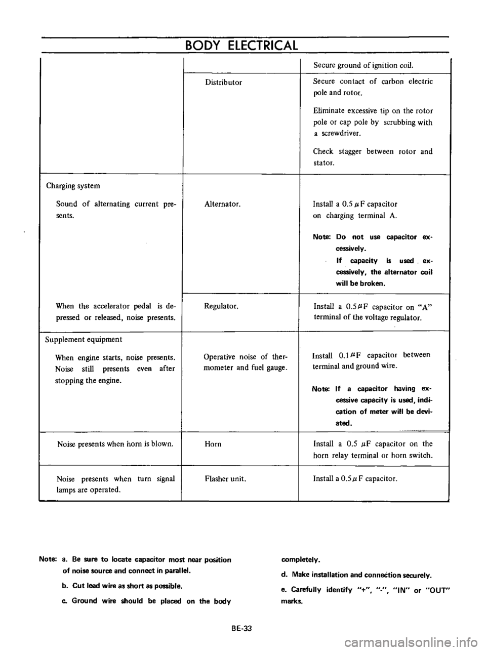
Distributor
Secure
ground
of
ignition
coil
Secure
contact
of
carbon
electric
pole
and
rotor
Eliminate
excessive
tip
on
the
rotor
pole
or
cap
pole
by
scrubbing
with
a
screwdriver
Check
stagger
between
rotor
and
stator
Charging
system
Sound
of
alternating
current
pre
sents
Alternator
Install
a
0
5
l
F
capacitor
on
charging
terminal
A
Note
Do
not
use
capacitor
ex
cessively
If
capacity
is
used
ex
cessively
the
alternator
coil
will
be
broken
When
the
accelerator
pedal
is
de
pressed
or
released
noise
presents
Regulator
Install
a
0
5
l
F
capacitor
on
A
terrninal
of
the
voltage
regulator
Supplement
equipment
When
engine
starts
noise
presents
Noise
still
presents
even
after
stopping
the
engine
Operative
noise
of
ther
rnometer
and
fuel
gauge
Install
0
1
l
F
capacitor
between
terminal
and
ground
wire
Note
If
a
capacitor
having
ex
cessive
capacity
is
used
indi
cation
of
meter
will
be
devi
ated
Noise
presents
when
horn
is
blown
Horn
Install
a
0
5
IF
capacitor
on
the
horn
relay
terminal
or
horn
switch
Noise
presents
when
turn
signal
lamps
are
operated
Flasher
unit
Install
a
0
5
l
F
capacitor
Note
a
Be
sure
to
locate
capacitor
most
near
position
of
noise
source
and
connect
in
parallel
completely
d
Make
installation
and
conneCtion
securely
b
Cut
lead
wire
as
short
as
possible
c
Ground
wire
should
be
placed
on
the
body
e
Carefully
identify
marks
IN
or
OUT
BE
33
Page 345 of 513
ENGINE
MECHANICAL
I
I
J
I
v
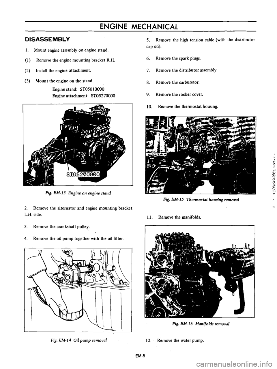
Fig
EM
13
Engine
on
engine
stand
DISASSEMBLY
1
Mount
engine
assembly
on
engine
stand
I
Remove
the
engine
mounting
bracket
R
H
2
Install
the
engine
attachment
3
Mount
the
engine
on
the
stand
Engine
stand
ST050
10000
Engine
attachment
ST05270000
2
Remove
the
alternator
and
engine
mounting
bracket
L
H
side
3
Remove
the
crankshaft
pulley
4
Remove
the
oil
pump
together
with
the
oil
ftIter
Fig
EM
14
Oil
pump
removal
5
Remove
the
high
tension
cable
with
the
distributor
cap
on
6
Remove
the
spark
plugs
7
Remove
the
distributor
assembly
8
Remove
the
carburetor
9
Remove
the
rocker
cover
10
Remove
the
thermostat
housing
Fig
EM
15
Thermostat
housing
removal
I
L
Remove
the
manifolds
Fig
EM
16
Manifolds
removal
12
Remove
the
water
pump
EM
5
Page 372 of 513
ENGINE
27
Install
the
oil
pump
with
oil
filter
28
Install
the
alternator
fan
and
fan
belt
29
Install
the
fuel
pump
30
Install
the
distributor
assembly
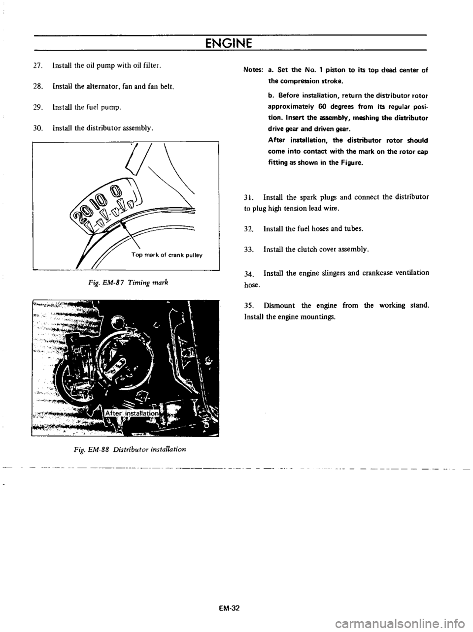
Fig
EM
B7
Timing
maTk
Fig
EM
SS
Distributor
installation
EM
32
Notes
3
Set
the
No
1
piston
to
its
top
dead
center
of
the
compression
stroke
b
Before
installation
return
the
distributor
rotor
approximately
60
degrees
from
its
regular
posi
tion
Insert
the
assembly
meshing
the
distributor
drive
gear
and
driven
gear
After
installation
the
distributor
rotor
should
come
into
contact
with
the
mark
on
the
rotor
cap
fitting
as
shown
in
the
Figure
31
Install
the
spark
plugs
and
connect
the
distributor
to
plug
high
tension
lead
wire
32
Install
the
fuel
hoses
and
tubes
33
Install
the
clutch
cover
assembly
34
Install
the
engine
stingers
and
crankcase
ventilation
hose
35
Dismount
the
engine
from
the
working
stand
Install
the
engine
mountings
Page 404 of 513
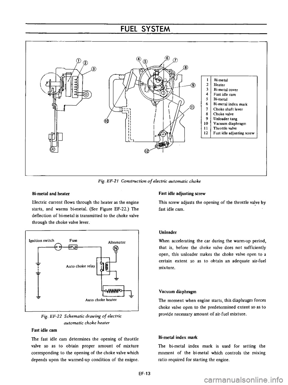
FUEl
SYSTEM
l
I
@
1J
w
I
I
I
I
1
1
1
t
2
3
4
5
6
7
8
9
10
tt
12
Hi
metal
Heater
Bi
metal
cover
Fast
idle
earn
Bi
metal
Bi
metal
index
mark
Choke
shaft
lever
Choke
valve
Unloader
tang
Vacuum
diaphragm
Throttle
valve
Fast
idle
adjusting
screw
j
@
Fig
EP
21
Construction
of
electric
automatic
choke
Bi
metal
and
heater
Electric
current
flows
through
the
heater
as
the
engine
starts
and
warms
bi
metal
See
Figure
EF
22
The
deflection
of
bi
metal
is
transmitted
to
the
choke
valve
through
the
choke
valve
lever
Ignition
switch
Fuse
Alternator
T
o
o
Auto
choke
relay
Auto
choke
heater
Fig
EF
22
Schematic
drawing
of
electric
automatic
choke
heater
Fast
idle
C3m
The
fast
idle
cam
determines
the
opening
of
throttle
valve
so
as
to
obtain
proper
amount
of
mixture
corresponding
to
the
opening
of
the
choke
valve
which
depends
upon
the
warmed
up
condition
of
the
enigne
Fast
idle
adjusting
screw
This
screw
adjusts
the
opening
of
the
throttle
valve
by
fast
idle
cam
Unloader
When
accelerating
the
car
during
the
warm
up
period
that
is
before
the
choke
valve
does
not
sufficiently
open
this
unloader
makes
the
choke
valve
open
to
a
certain
extent
so
as
to
obtain
an
adequate
air
fuel
mixture
Vacuum
diaphragm
The
moment
when
engine
starts
this
diaphragm
forces
choke
valve
open
to
the
predetermined
extent
so
as
to
provide
necessary
amount
of
air
fuel
mixture
Bi
metaI
index
mark
The
bi
metal
index
mark
is
used
for
setting
the
moment
of
the
bi
metal
which
controls
the
mixing
ratio
required
for
starting
the
engine
EF
13
Page 420 of 513
DATSUN
1200
MODEL
B
11
0
SERIES
L
NISSAN
I
NISSAN
MOTOR
CO
LTD
TOKYO
JAPAN
SECTION
EE
ENGINE
ELECTRICAL
SYSTEM
BATTERY
STARTING
MOTOR
CHARGING
CIRCUIT
ALTERNATOR
REGULATOR
IGNITIO
N
CIRCUIT
DISTRIBUTOR
IGNITION
COIL
SPARK
PLUG
EEl
EE
3
EE
15
EE
16
EE
23
EE
29
EE
29
EE
36
EE
37