1973 DATSUN B110 air bleeding
[x] Cancel search: air bleedingPage 102 of 513
CHASSIS
Note
a
Before
tightening
the
gland
packing
pull
the
piston
rod
approximately
90
mm
3
543
in
upward
This
will
provide
the
shock
absorber
system
with
the
best
condition
for
bleeding
b
Gland
packing
tightening
torque
is
rated
at
8
0
to
11
0
kg
m
57
8
to
79
5
ft
Ib
However
arm
length
of
this
tool
is
extended
by
100
mm
3
94
in
as
shown
in
the
following
figure
Thus
when
actually
tightening
the
gland
packing
measure
effective
length
L
of
a
torque
wrench
to
be
used
and
set
up
torque
wrench
value
based
on
the
following
formula
C
10
x
l
I
kg
m
C
70
x
l
I
ft
lbJ
100
l
3
94
where
C
Value
read
on
the
torque
wrench
kg
m
ft
lbIJ
Effective
length
of
torque
wrench
mm
in
l
TOROUE
WRENCH
GLAND
PACKING
WRENCH
I
C
4
F
r
I
L
I
100
mm
3
94
in
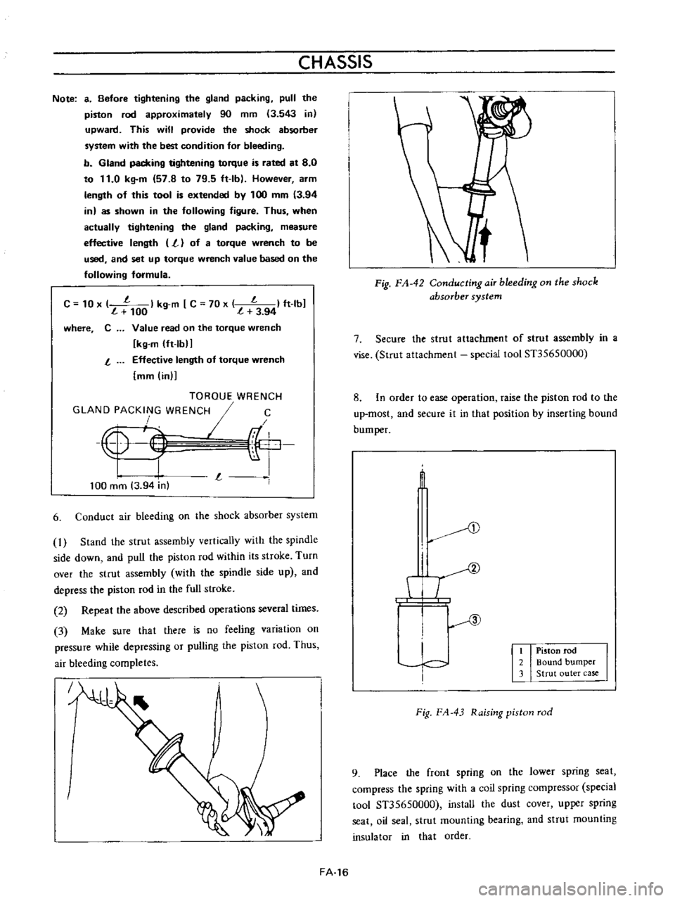
6
Conduct
air
bleeding
on
the
shock
absorber
system
1
Stand
the
strut
assembly
vertically
with
the
spindle
side
down
and
pull
the
piston
rod
within
its
stroke
Turn
over
the
strut
assembly
with
the
spindle
side
up
and
depress
the
piston
rod
in
the
full
stroke
2
Repeat
the
above
described
operations
several
times
3
Make
sure
that
there
is
no
feeling
variation
on
pressure
while
depressing
or
pulling
the
piston
rod
Thus
air
bleeding
completes
J
FA
16
Fig
FA
42
ConductingaiT
bleeding
on
the
shock
absorber
system
7
Secure
the
strut
attachment
of
strut
assembly
in
a
vise
Strut
attachment
special
tool
Sn5650000
8
In
order
to
ease
operation
raise
the
piston
rod
to
the
up
most
and
secure
it
in
that
position
by
inserting
bound
bum
per
t
D
I
T
I
c
I
Piston
rod
2
Bound
bumper
3
Strut
outer
case
Fig
FA
43
Raising
piston
rod
9
Place
the
front
spring
on
the
lower
spring
seat
compress
the
spring
with
a
coil
spring
compressor
special
tool
Sn5650000
install
the
dust
cover
upper
spring
seat
oil
seal
strut
mounting
bearing
and
strut
mounting
insulator
in
that
order
Page 128 of 513
CHASSIS
Ii
t
L
1
J
rJ
I
e
i
L
rubber
parts
und
alcohol
long
than
30
seconds
After
the
parts
are
cleaned
dry
them
with
com
pressed
air
Check
the
cylinder
and
piston
for
damage
and
uneven
wear
on
the
sliding
surface
and
for
other
defective
conditions
Replace
as
required
2
Replace
if
the
cylinder
and
piston
clearance
is
more
than
0
15
mm
0
006
in
3
In
principle
replace
the
piston
cup
packing
and
valves
with
new
ones
whenever
the
master
cylinder
is
disassembled
Be
sure
to
replace
if
damaged
worn
weakened
or
expanded
4
Check
the
return
springs
for
wear
damage
and
other
defective
conditions
and
replace
as
required
5
Replace
others
if
deformed
damaged
or
defective
Reassembly
Assemble
the
master
cylinder
in
reverse
sequence
of
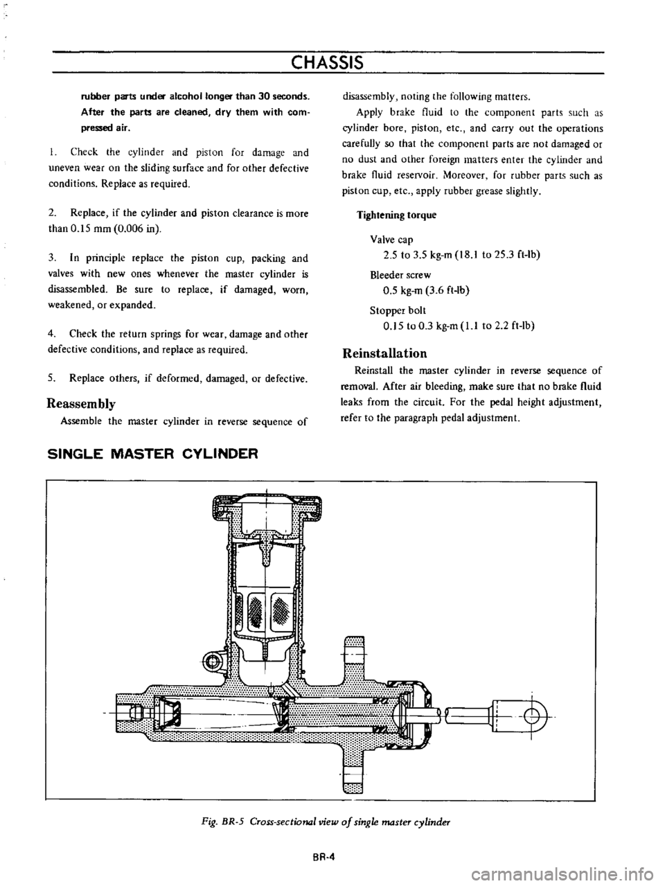
SINGLE
MASTER
CYLINDER
s
m
e
disassembly
noting
the
following
matters
Apply
brake
fluid
to
the
component
parts
such
as
cylinder
bore
piston
etc
and
carry
out
the
operations
carefully
so
that
the
component
parts
are
not
damaged
or
no
dust
and
other
foreign
matters
enter
the
cylinder
and
brake
fluid
reselVoir
Moreover
for
rubber
parts
such
as
piston
cup
etc
apply
rubber
grease
slightly
Tightening
torque
Valve
cap
2
5
to
3
5
kg
m
I8
to
25
3
ft
Ib
Bleeder
screw
0
5
kg
m
3
6
ft
lb
Stopper
bolt
0
5
to
0
3
kg
m
l
I
to
2
2ft
lb
Reinstallation
Reinstall
the
master
cylinder
in
reverse
sequence
of
removal
After
air
bleeding
make
sure
that
no
brake
fluid
leaks
from
the
circuit
For
the
pedal
height
adjustment
refer
to
lhe
paragraph
pedal
adjustment
r
11L
y
Fig
BR
5
Cross
sectional
view
of
single
master
cylinder
BR
4
Page 131 of 513

Tightening
torque
3
way
connector
1
5
to
1
8
kg
m
10
8
to
13
0
ft
lh
1
5
to
1
8
kg
m
10
8
to
13
0
ft
lh
1
5
to
1
8
kg
m
10
8
to
13
0
ft
lb
0
7
to
0
9
kg
m
5
1
to
6
5
ft
1b
Master
cylinder
Brake
hose
Air
bleeder
5
Fill
the
master
cylinder
brake
fluid
reservoir
with
brake
fluid
and
perform
air
bleeding
complele1y
Note
a
Do
not
use
brake
fluid
other
than
specified
b
The
specified
brake
fluid
is
used
for
both
single
and
tandem
type
master
cylinders
6
Upon
completion
of
air
bleeding
make
sure
that
the
brake
operates
correctly
and
check
the
brake
tube
and
hose
connectors
for
fluid
leaking
Fully
depress
the
brake
pedal
continue
to
depress
the
brake
pedal
for
several
seconds
and
make
sure
that
no
brake
fluid
leaks
from
any
part
of
the
brake
line
Replace
defective
part
if
required
Brake
line
pressure
differential
warning
light
switch
A
warning
light
is
located
on
the
instrument
panel
to
warn
the
driver
when
a
pressure
difference
of
13
to
17
kg
cm2
185
to
2421bJsq
in
exists
between
the
front
and
rear
b
rake
systems
A
hydraulically
actuated
warning
light
switch
is
located
in
the
engine
compartment
Both
front
and
rear
brake
systems
are
connected
to
this
switch
assembly
When
a
pressure
difference
of
13
to
17
kgJcm2
185
to
242
lbJsq
in
occurs
between
the
front
and
rear
brake
systems
the
valves
will
shuttle
toward
the
side
with
the
low
pressure
The
valve
contacts
with
the
switch
terminal
BRAKE
the
ground
circuit
for
the
warning
light
is
completed
and
thus
the
warning
light
lights
In
this
case
correct
the
hydraulic
brake
problem
and
bleed
the
brakes
Check
the
warning
light
switch
assembly
for
a
proper
operation
Check
the
switch
assembly
for
fluid
leakage
Note
Do
not
attempt
to
repair
switch
for
any
reason
replace
switch
assembly
completely
1
To
front
brake
L
H
2
From
master
cylinder
F
3
From
master
cylinder
R
4
To
rear
brake
L
B
R
M
5
To
front
brake
R
H
Fig
BR
12
Warning
light
switch
r
I
@
I
I
3
I
Valve
assembly
4
Piston
load
spring
Wire
terminal
Brake
tube
Fig
BR
13
Sectional
view
of
warning
light
switch
BR
7
Page 134 of 513
CHASSIS
Fig
BR
19
Greasing
points
on
brake
disc
3
Tighten
the
brake
disc
installation
bolt
to
2
7
to
3
7
kg
m
19
5
to
26
7
ft
lb
4
Adjust
brake
shoe
clearance
and
perform
air
bleeding
on
the
hydraulic
system
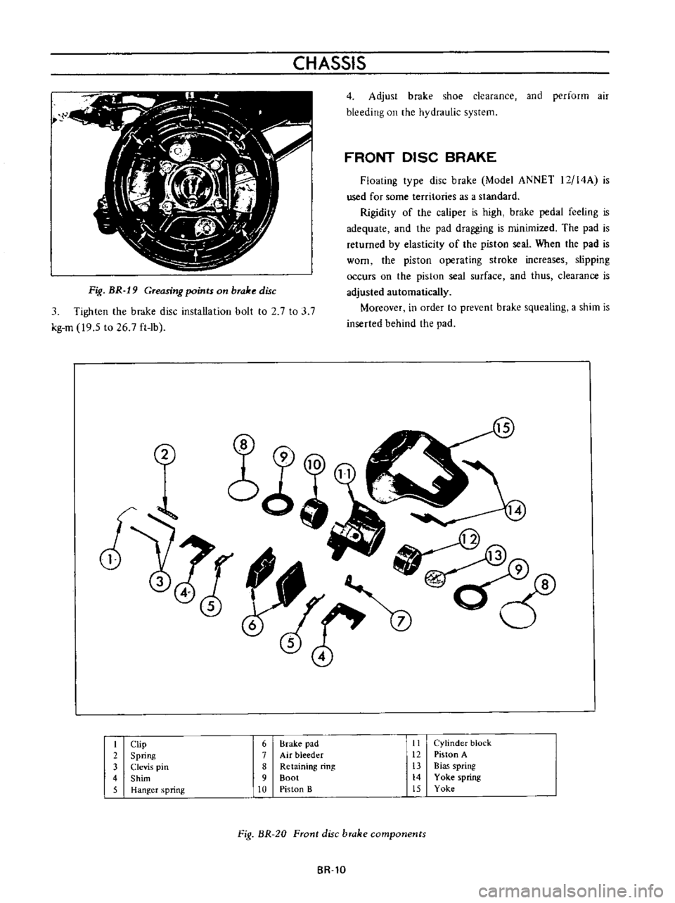
FRONT
DISC
BRAKE
Floating
type
disc
brake
Model
ANNET
12
14A
is
used
for
some
territories
as
a
standard
Rigidity
of
the
caliper
is
high
brake
pedal
feeling
is
adequate
and
the
pad
dragging
is
minimized
The
pad
is
returned
by
elasticity
of
the
piston
seal
When
the
pad
is
worn
the
piston
operating
stroke
increases
slipping
occurs
on
the
piston
seal
surface
and
thus
clearance
is
adjusted
automatically
Moreover
in
order
to
prevent
brake
squealing
a
shim
is
inserted
behind
the
pad
2
I
Clip
6
Brake
pad
II
Cylinder
block
2
Spring
7
Air
bleeder
12
Piston
A
3
Clevis
pin
8
Retaining
ring
13
Bias
spring
4
Shim
9
Boot
14
Yoke
spring
5
Hanger
spring
10
Piston
B
15
Yoke
Fig
BR
20
Front
disc
brake
components
BR
lO
Page 146 of 513
CHASSIS
2
Upon
completion
of
the
adjustment
release
the
hand
brake
lever
and
make
sure
that
the
rear
wheels
are
not
braked
Normal
stroke
78
5
mm
3
091
in
6
notches
Limited
stroke
136
0
mm
5
35
in
10
notches
The
term
Stroke
means
height
from
the
standard
position
220
mm
8
7
in
above
the
hand
brake
lever
fulcrum
Note
Readjust
hand
brake
stroke
when
it
reaches
the
limited
stroke
136
mm
5
35
inl
10
notches
Bleeding
hydraulic
system
Bleeding
the
hydraulic
brake
system
deserves
much
attention
as
it
is
an
essential
factor
for
regular
service
brake
operation
As
a
matter
of
fact
during
the
brake
service
air
is
likely
to
creep
into
the
circuit
with
the
result
that
the
fluid
action
is
altered
and
the
brake
pedal
becomes
spongy
at
the
travel
end
Bleeding
should
be
carried
out
at
first
with
the
masler
cylinder
then
from
the
longest
line
from
the
master
cylinder
and
then
finish
up
with
the
shortest
Note
Always
clear
away
any
dirt
around
master
cylinder
reservoir
cover
before
removing
cover
for
any
reason
Never
depress
pedal
while
brake
drums
are
removed
unless
bleeder
valve
is
open
Top
up
the
reservoir
master
cylinder
with
fluid
of
the
recommended
type
2
Thoroughly
wipe
the
bleeder
screw
and
from
any
mud
or
dust
present
so
that
the
outlet
hole
is
free
from
foreign
matter
3
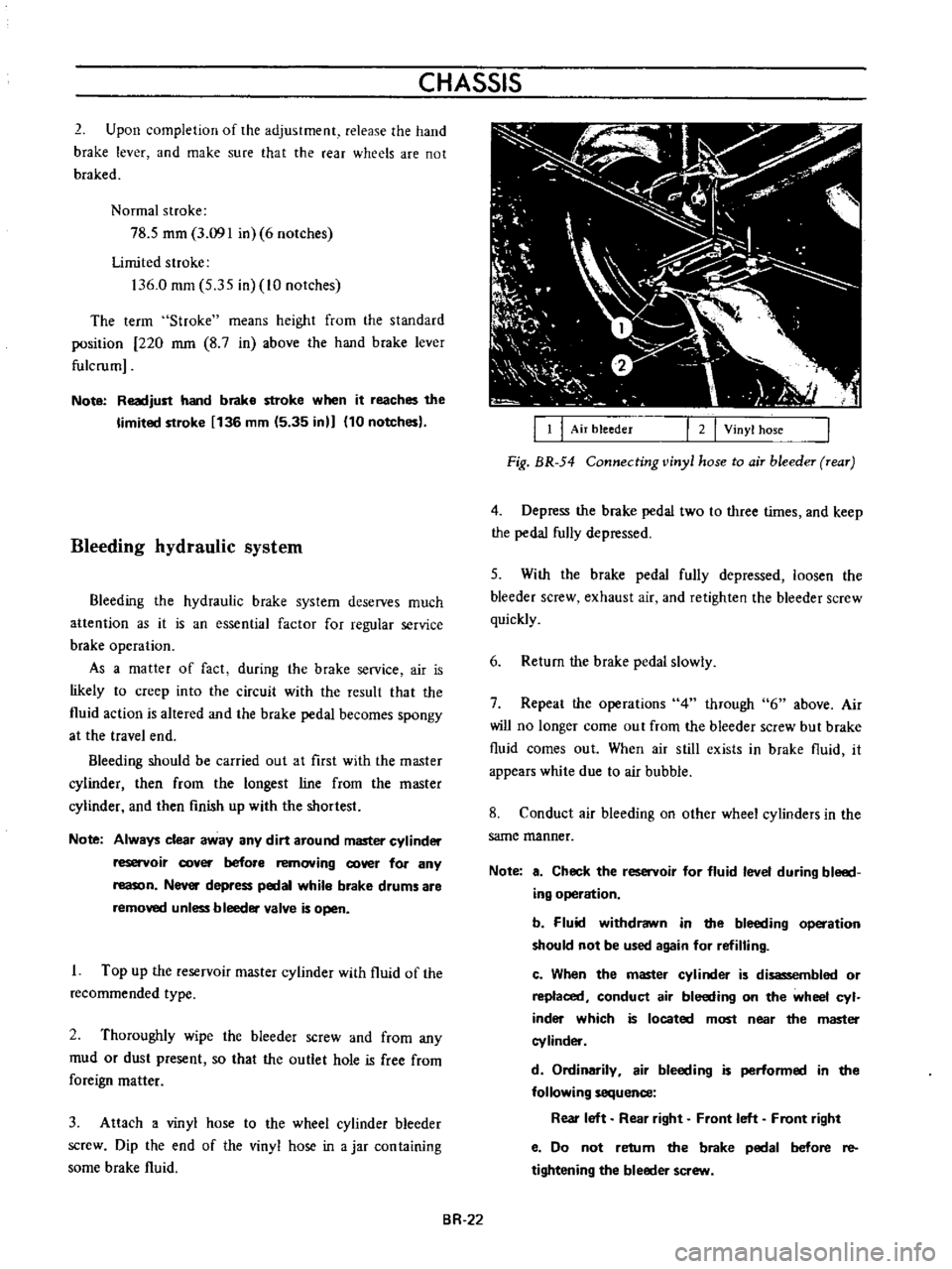
Attach
a
vinyl
hose
to
the
wheel
cylinder
bleeder
screw
Dip
the
end
of
the
vinyl
hose
in
a
jar
con
taining
some
brake
fluid
BR
22
I
I
I
Air
bleeder
I
2
I
Vinyl
hose
Fig
BR
54
Connecting
vinyl
hose
to
air
bleeder
rear
4
Depress
the
brake
pedal
two
to
three
times
and
keep
the
pedal
fully
depressed
5
With
the
brake
pedal
fully
depressed
loosen
the
bleeder
screw
exhaust
air
and
retighten
the
bleeder
screw
quickly
6
Return
the
brake
pedal
slowly
7
Repeat
the
operations
4
through
6
above
Air
will
no
longer
come
out
from
the
bleeder
screw
but
brake
fluid
comes
out
When
air
still
exists
in
brake
fluid
it
appears
white
due
to
air
bubble
8
Conduct
air
bleeding
on
other
wheel
cylinders
in
the
same
manner
Note
a
Check
the
reservoir
for
fluid
level
during
bleed
ing
operation
b
Fluid
withdrawn
in
the
bleeding
operation
should
not
be
used
again
for
refilling
c
When
the
master
cylinder
is
disassembled
or
replaced
conduct
air
bleeding
on
the
wheel
cyl
inder
which
is
located
most
near
the
master
cylinder
d
Ordinarily
air
bleeding
is
performed
in
the
following
sequence
Rear
left
Rear
right
Front
left
Front
right
e
Do
not
retum
the
brake
pedal
before
re
tightening
the
bleeder
screw
Page 481 of 513
CLUTCH
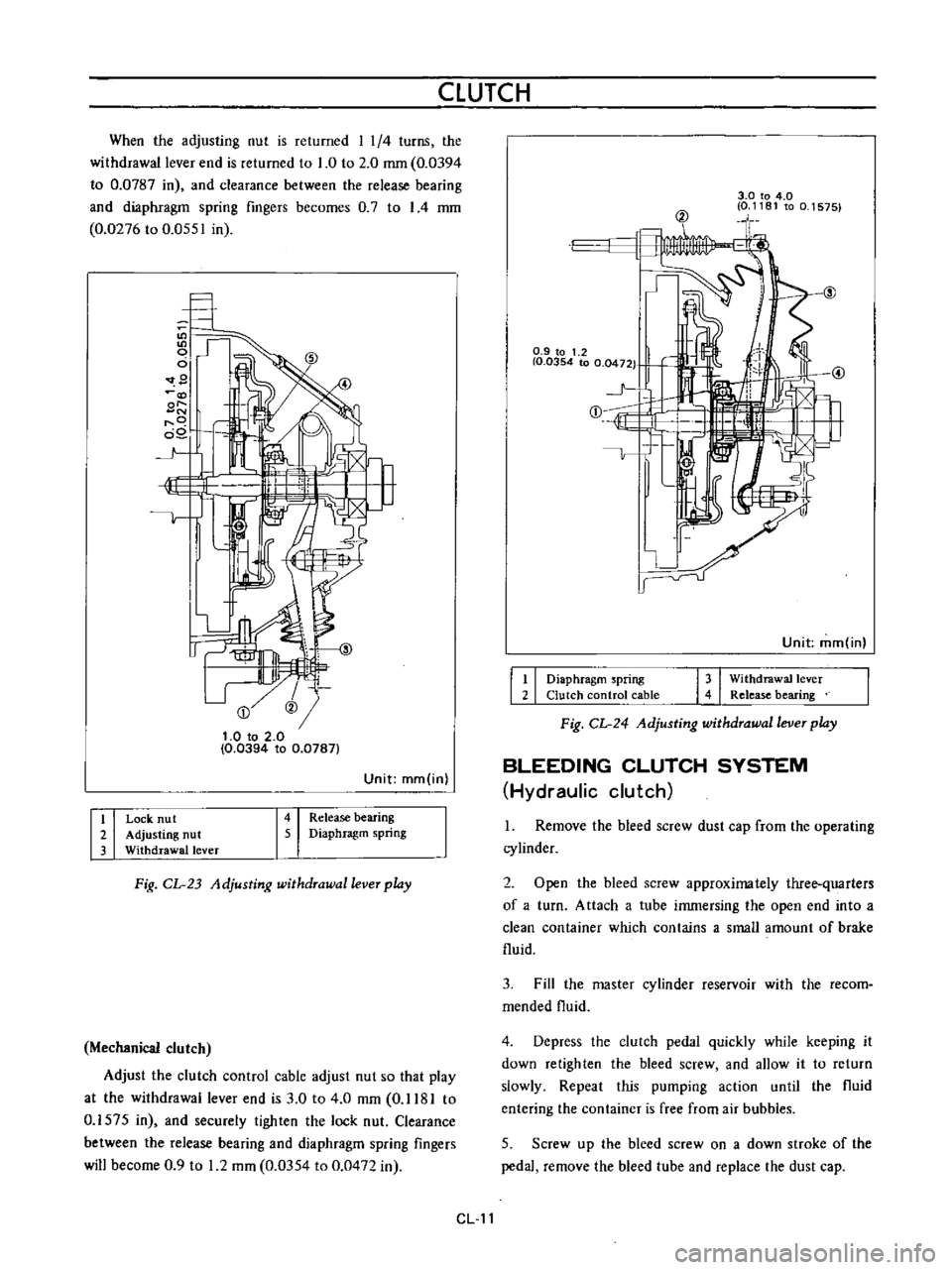
When
the
adjusting
nut
is
returned
I
1
4
turns
the
withdrawal
lever
end
is
returned
to
1
0
to
2
0
mm
0
0394
to
0
0787
in
and
clearance
between
the
release
bearing
and
diaphragm
spring
fingers
becomes
0
7
to
I
4
mm
0
0276
to
0
0551
in
9
@
t
O
to
2
0
0
0394
to
0
0787
Unit
mm
in
I
i
I
I
I
Release
bearing
Diaphragm
spring
Lock
nu
t
Adjusting
nut
Withdrawal
lever
Fig
CL
23
Adjusting
withdrawal
lever
play
Mechanical
clutch
Adjust
the
clutch
control
cable
adjust
nut
so
that
play
at
the
withdrawal
lever
end
is
3
0
to
4
0
mm
0
1181
to
0
1575
in
and
securely
tighten
the
lock
nut
Clearance
between
the
release
bearing
and
diaphragm
spring
fingers
will
become
0
9
to
1
2
mm
0
0354
to
0
0472
in
3
0
to
4
0
0
1181
to
0
1575
@
0
9
to
1
2
I
0
0354
to
0
0472
1
j
E
1
Unit
mm
in
I
I
I
I
Diaphragm
spring
Clutch
control
cable
Withdrawal
lever
Release
bearing
Fig
CL
24
Adjusting
withdrawal
lever
play
BLEEDING
CLUTCH
SYSTEM
Hydraulic
clutch
1
Remove
the
bleed
screw
dust
cap
from
the
operating
cylinder
2
Open
the
bleed
screw
approximately
three
quarters
of
a
turn
Attach
a
tube
immersing
the
open
end
into
a
clean
container
which
contains
a
small
amount
of
brake
fluid
3
Fill
the
master
cylinder
reservoir
with
the
recom
mended
fluid
4
Depress
the
clutch
pedal
quickly
while
keeping
it
down
retighten
the
bleed
screw
and
allow
it
to
return
slowly
Repeat
this
pumping
action
until
the
fluid
entering
the
container
is
free
from
air
bubbles
5
Screw
up
the
bleed
screw
on
a
down
stroke
of
the
pedal
remove
the
bleed
tube
and
replace
the
dust
cap
CL
11