1973 DATSUN B110 heater
[x] Cancel search: heaterPage 228 of 513
@
c
@
CD
w
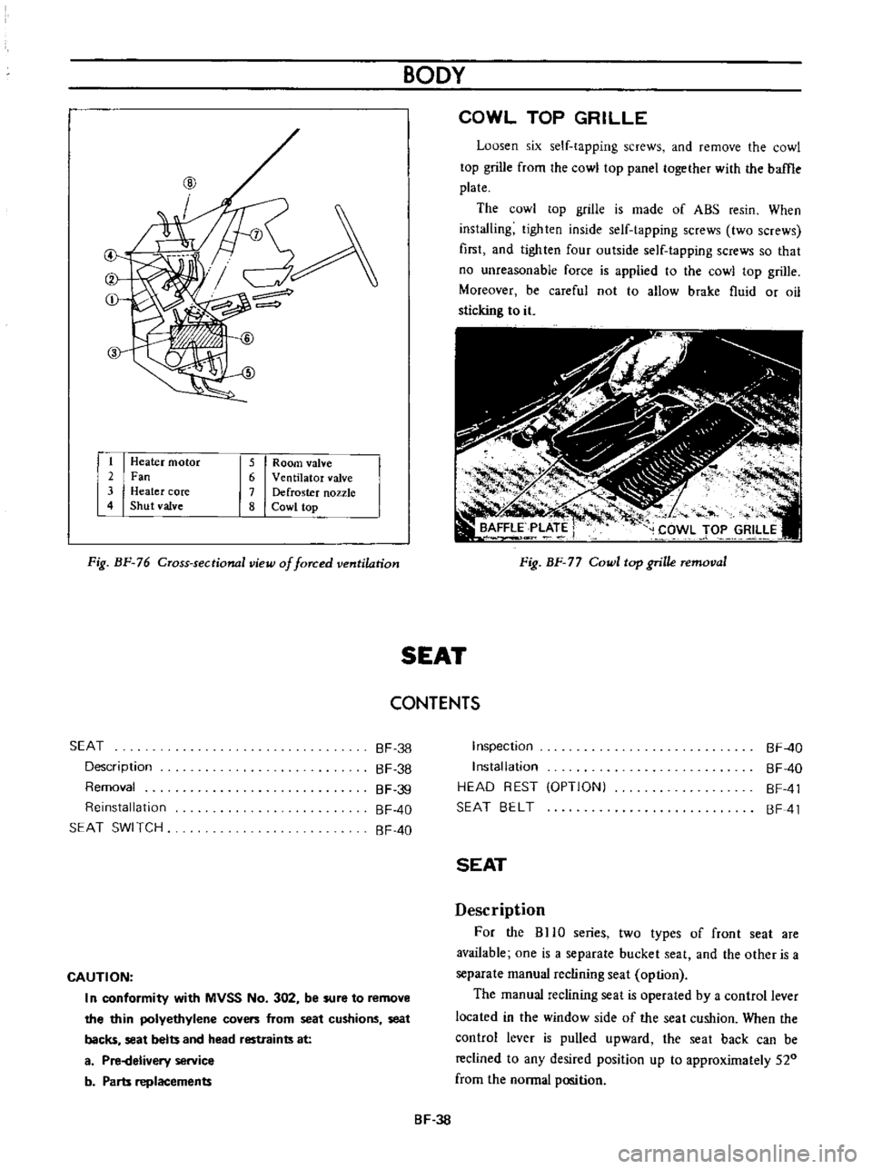
1
Heater
motor
2
Fan
3
Heater
core
4
Shut
valve
5
Room
valve
6
Ventilator
valve
7
Defroster
nozzle
8
Cowl
top
Fig
BF
76
Cross
sectional
view
of
forced
ventilation
BODY
COWL
TOP
GRILLE
Loosen
six
self
tapping
screws
and
remove
the
cowl
top
grille
from
the
cowl
top
panel
together
with
the
baffle
plate
The
cowl
top
grille
is
made
of
ABS
resin
When
installing
tighten
inside
self
tapping
screws
two
screws
first
and
lighten
four
outside
self
tapping
screws
so
that
no
unreasonable
force
is
applied
to
the
cowl
top
grille
Moreover
be
careful
not
to
allow
brake
fluid
or
oil
sticking
to
it
Fig
BF
77
Cowl
top
grille
removal
SEAT
CONTENTS
SEAT
Description
Removal
Reinstallation
SEAT
SWI
TCH
BF
38
BF
38
BF
39
BF
40
BF
40
CAUTION
I
n
conformity
with
MVSS
No
302
be
sure
to
remove
the
thin
polyethylene
covers
from
seat
cushions
seat
backs
seat
belts
and
head
restraints
at
a
Pi
Helivery
service
b
Parts
replacements
Inspection
Installation
HEAD
REST
OPTIONI
SEAT
BELT
BF
40
BF
40
BF
41
BF
41
SEAT
Description
For
the
BHO
series
two
types
of
front
seat
are
available
one
is
a
separate
bucket
seat
and
the
other
is
a
separate
manual
reclining
seat
option
The
manual
reclining
seat
is
operated
by
a
control
lever
located
in
the
window
side
of
the
seat
cushion
When
the
control
lever
is
pulled
upward
the
seat
back
can
be
reclined
to
any
desired
position
up
to
approximately
520
from
the
normal
position
BF
38
Page 232 of 513

BODY
INSTRUMENT
PANEL
CONTENTS
REMOVAL
BF
42
REMOVAL
Fig
BF
88
Removing
instrument
panel
Note
There
are
two
types
of
instrument
panel
square
type
and
round
type
However
both
of
them
are
removed
and
reinstalled
in
the
same
manner
Disconnect
the
battery
cable
at
the
battery
terminal
2
Disconnect
the
wiring
harness
connector
units
Disconnect
the
instrument
harness
from
the
engine
compartment
harness
Disconnect
the
instrument
harness
from
the
turn
signal
switch
Disconnect
the
instrument
harness
frorn
the
body
harness
Disconnect
the
instrumen
t
harness
connected
to
the
door
switch
stop
lamp
switch
flasher
unit
and
passing
light
relay
option
REINSTALLATION
BF
43
Note
When
disconnecting
the
wiring
harness
recom
mend
to
use
tags
for
identifying
their
relationship
3
Disconnect
cables
for
radio
antenna
and
speaker
4
Remove
the
package
tray
the
shell
cover
and
turn
signal
switch
Note
Work
may
be
carried
out
without
removing
die
steering
wheel
However
it
is
recommended
to
remove
the
steering
wheel
50
that
work
can
be
carried
out
more
easily
5
Disconnect
the
speedometer
cable
from
the
speedometer
unit
6
Disconnect
the
heater
control
cable
at
the
heater
side
Fig
BF
89
Removing
imtrument
panel
Ii
BF
42
Page 235 of 513
DATSUN
1200
MODEL
B
11
0
SERIES
I
NISSAN
I
NISSAN
MOTOR
CO
LTD
TOKYO
JAPAN
SECTION
BE
BODY
ELECTRICAL
WIRING
FUSE
LIGHTING
SYSTEM
HORN
METERS
AND
GAUGES
WINDSHIELD
WIPER
AND
WASHER
IGNITION
SWITCH
AND
STEERING
LOCK
CLOCK
RADIO
HEATER
BE
1
BE
6
BE
7
BE
15
BE
18
BE
26
BE
29
BE
31
BE
32
BE
34
Page 245 of 513
BULB
SPECIFICATIONS
Headlight
unit
Directional
and
parking
light
Side
marker
light
License
plate
light
Rear
combination
light
Taillight
Stop
brake
light
Turn
signal
light
Back
up
light
Meter
illuminating
lamp
Wiper
Washer
illumination
lamp
Heater
control
illumination
lamp
Ignition
warning
light
Turn
signal
indicator
light
Headlight
beam
indicator
light
Oil
pressure
warning
light
Brake
warning
ligh
t
Room
light
TURN
SIGNAL
AND
DIMMER
COMBINATION
SWITCH
Removal
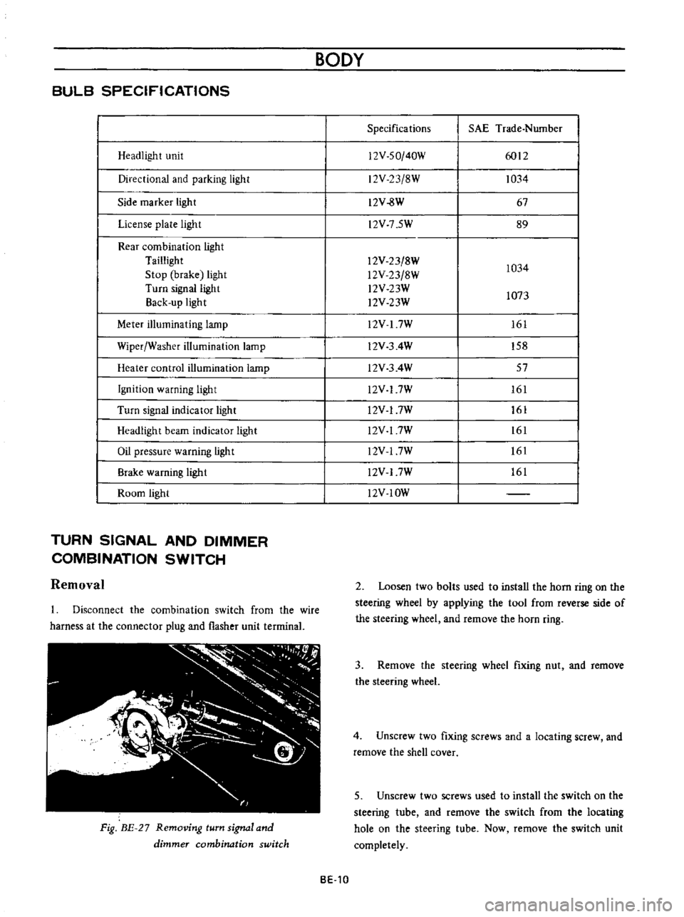
Disconnect
the
combination
switch
from
the
wire
harness
at
the
connector
plug
and
flasher
unit
terrninal
Fig
BE
27
Removing
turn
signal
and
dimmer
combination
switch
BODY
Specifications
SAE
Trade
Number
12V
SO
40W
6012
12V
23
8W
1034
12V
8W
67
l2V
7
5W
89
12V
23
8W
1034
l2V
23
8W
l2V
23W
1073
l2V
23W
12V
I
7W
161
l2V
3
4W
158
l2V
3
4W
57
l2V
17W
161
l2V
17W
161
l2V
17W
161
l2V
17W
161
l2V
17W
161
l2V
IOW
2
Loosen
two
bolts
used
to
install
the
horn
ring
on
the
steering
wheel
by
applying
the
tool
from
reverse
side
of
the
steering
wheel
and
remove
the
horn
ring
3
Remove
the
steering
wheel
fixing
nut
and
remove
the
steering
wheel
4
Unscrew
two
fixing
screws
and
a
locating
screw
and
remove
the
shell
cover
5
Unscrew
two
screws
used
to
install
the
switch
on
the
steering
tube
and
remove
the
switch
from
the
locating
hole
on
the
steering
tube
Now
remove
the
switch
unit
completely
BE
10
Page 253 of 513

BODY
METERS
AND
GAUGES
CONTENTS
CLUSTER
LID
Oescri
ption
Removal
SPEEDOMETER
Replacement
FUEL
GAUGE
AND
TEMPERATURE
GAUGE
Description
Replacement
BE
1B
BE
18
BE
18
BE
19
BE
19
BE
19
BE
19
BE
20
CLUSTER
LID
Description
The
cluster
lid
holds
various
rneters
indicators
and
clock
located
around
the
speedorneter
Printed
circuit
board
is
used
at
the
back
of
the
meter
as
shown
in
Figure
BE
38
and
the
printed
circuit
board
is
connected
with
multiple
connectors
Thus
the
meters
Can
be
inspected
and
serviced
extremely
easily
Except
for
the
speed
ometer
all
rneters
are
operated
electrically
The
fuel
gauge
and
therrnometer
are
very
reliable
and
they
are
equipped
with
bimetal
devices
F
a
o
ill
I
1
a
a
Fig
BE
34
Combination
meters
Removal
Disconnect
the
battery
terminal
depressing
the
OIL
PRESSURE
AND
IGNITION
WARNING
LAMPS
HAND
BRAKE
WARNING
LAMP
BULB
SPECIFICATIONS
TROUBLE
DIAGNOSES
AND
CORRECTIONS
Speedometer
Thermometer
and
fuel
meter
Oil
pressure
and
ignition
warning
lamps
BE
20
BE
21
BE
21
BE
22
BE
22
BE
23
BE
25
windshield
wiper
switch
lighting
switch
and
choke
lever
knobs
turn
them
counterclockwise
to
remove
Remove
the
escutcheon
2
Inserting
your
hand
into
back
of
the
cluster
lid
disconnect
the
cigarette
lighter
cable
and
turn
and
remove
the
cigarette
lighter
outer
case
3
Remove
the
radio
and
heater
control
knobs
4
Remove
the
shell
cover
from
the
steering
tube
loosen
the
screws
used
to
secure
the
meter
housing
to
the
instrument
panel
and
remove
the
cluster
lid
5
Pull
out
the
l2
pole
round
shape
connector
and
remove
the
speedometer
cable
union
nut
6
Remove
the
cluster
lid
from
the
instrument
panel
Fig
BE
35
Removing
clllSter
jd
BE
18
Page 254 of 513
BODY
ELECTRICAL
SPEEDOMETER
The
speedometer
is
equipped
with
a
total
odometer
which
records
travelled
distance
Replacement
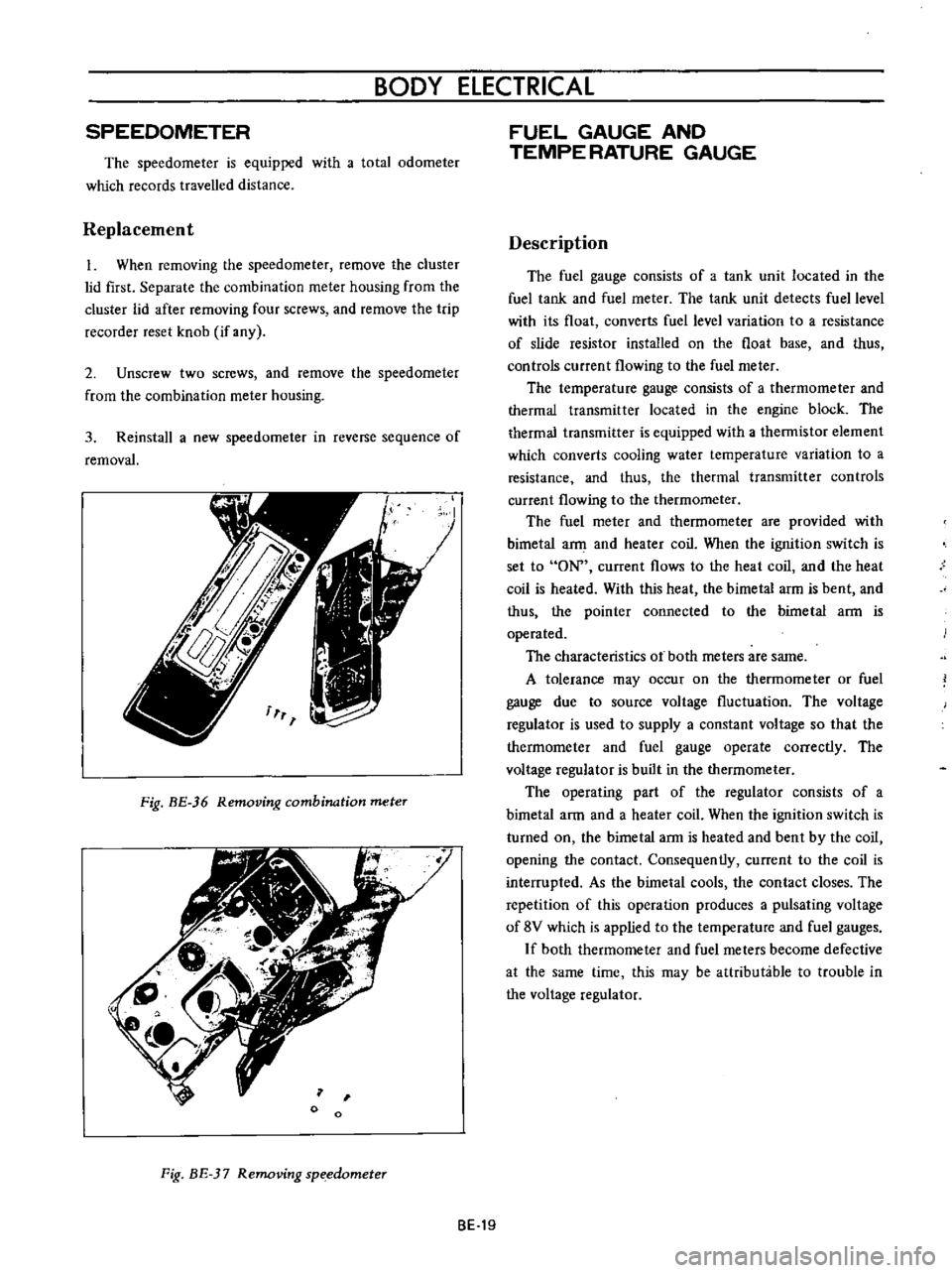
1
When
removing
the
speedometer
remove
the
cluster
lid
first
Separate
the
combination
meter
housing
from
the
cluster
lid
after
removing
four
screws
and
remove
the
trip
recorder
reset
knob
if
any
2
Unscrew
two
screws
and
remove
the
speedometer
from
the
combination
meter
housing
3
Reinstall
a
new
speedometer
in
reverse
sequence
of
removal
Fig
BE
36
Removing
combination
meter
o
Fig
BE
37
Removing
sp
edometer
FUEL
GAUGE
AND
TEMPE
RATURE
GAUGE
Description
The
fuel
gauge
consists
of
a
tank
unit
located
in
the
fuel
tank
and
fuel
meter
The
tank
unit
detects
fuel
level
with
its
float
converts
fuel
level
variation
to
a
resistance
of
slide
resistor
installed
on
the
float
base
and
thus
controls
current
flowing
to
the
fuel
meter
The
temperature
gauge
consists
of
a
thermorneter
and
thermal
transmitter
located
in
the
engine
block
The
thermal
transmitter
is
equipped
with
a
thermistor
element
which
converts
cooling
water
temperature
variation
to
a
resistance
and
thus
the
thermal
transmitter
controls
current
flowing
to
the
thermometer
The
fuel
rneter
and
thermometer
are
provided
with
bimetal
a
and
heater
coil
When
the
ignition
switch
is
set
to
ON
current
flows
to
the
heat
coil
and
the
heat
coil
is
heated
With
this
heat
the
bimetal
arm
is
bent
and
thus
the
pointer
connected
to
the
bimetal
ann
is
operated
The
characteristics
ot
both
meters
are
same
A
tolerance
may
occur
on
the
thermometer
or
fuel
gauge
due
to
source
voltage
fluctuation
The
voltage
regulator
is
used
to
supply
a
constant
voltage
so
that
the
therrnorneter
and
fuel
gauge
operate
correctly
The
voltage
regulator
is
built
in
the
thermometer
The
operating
part
of
the
regulator
consists
of
a
bimetal
arm
and
a
heater
coil
When
the
ignition
switch
is
turned
on
the
birnetal
arm
is
heated
and
bent
by
the
coil
opening
the
contact
Consequently
current
to
the
coil
is
interrupted
As
the
bimetal
cools
the
contact
closes
The
repetition
of
this
operation
produces
a
pulsating
voltage
of
8V
which
is
applied
to
the
ternperature
and
fuel
gauges
If
both
thermometer
and
fuel
meters
become
defective
at
the
same
time
this
may
be
attributable
to
trouble
in
the
voltage
regulator
BE
19
Page 269 of 513
Removal
and
installation
A
I
I
I
@
I
Removal
and
installation
BODY
HEATER
CONTENTS
BE
34
TROUBLE
DIAGNOSES
AND
CORRECTIONS
BE
35
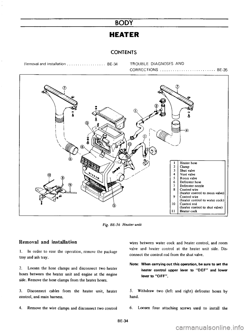
Fig
BE
56
Heater
unit
6
1
Heater
hose
2
Clamp
3
Shut
valve
4
Vent
valve
5
Room
valve
6
Defroster
hose
7
Defroster
nozzle
8
Control
wire
heater
control
to
room
valve
9
Control
wire
heater
control
to
water
cock
10
Control
rod
heater
control
to
shut
valve
11
Heater
cock
1
In
order
to
ease
the
operation
remove
the
package
tray
and
ash
tray
wires
between
water
cock
and
peater
control
and
room
valve
and
heater
control
at
the
heater
unit
side
Dis
connect
the
control
rod
from
the
shut
valve
2
Loosen
the
hose
clamps
and
disconnect
two
heater
hoses
between
the
heater
unit
and
engine
at
the
engine
side
Remove
the
hose
clamps
from
the
heater
hoses
Note
When
carrying
out
this
operation
be
sure
to
set
the
heater
control
upper
lever
to
OEF
and
lower
lever
to
OFF
3
Disconnect
cables
from
the
heater
unit
heater
control
and
main
harness
5
Withdraw
two
left
and
right
defroster
hoses
by
hand
4
Remove
the
wire
clamps
and
disconnect
two
control
6
Loosen
four
attaching
screws
used
to
install
the
BE
34
Page 270 of 513
BODY
ELECTRICAL
heater
unit
on
the
dash
board
and
remove
the
heater
unit
carefully
panel
8
Rernove
two
self
tapping
screws
from
back
of
the
instrument
panel
and
remove
the
defroster
nozzle
7
When
removing
the
heater
control
from
the
instru
ment
panel
remove
the
control
knob
and
loosen
two
screws
used
to
install
the
heater
control
on
the
instrument
9
The
heater
unit
is
installed
in
reverse
sequence
of
removal
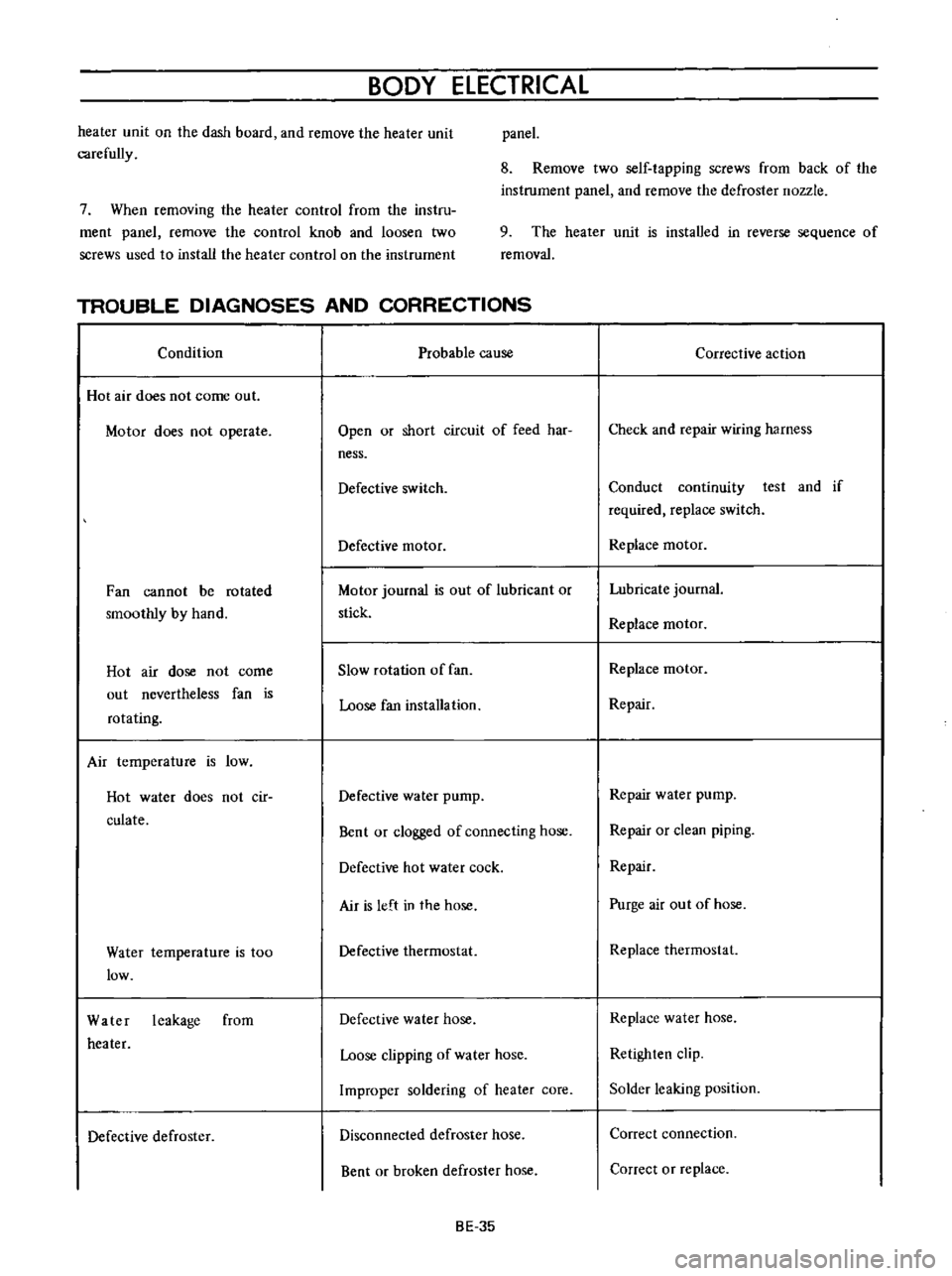
TROUBLE
DIAGNOSES
AND
CORRECTIONS
Condition
Probable
cause
Hot
air
does
not
come
out
Motor
does
not
operate
Open
or
short
circuit
of
feed
har
ness
Defective
switch
Defective
motor
Fan
cannot
be
rotated
smoothly
by
hand
Motor
journal
is
out
of
lubricant
or
stick
Hot
air
dose
not
come
out
nevertheless
fan
is
rotating
Slow
rotation
of
fan
Loose
fan
installation
Air
temperature
is
low
Hot
water
does
not
cir
culate
Defective
water
pump
Bent
or
clogged
of
connecting
hose
Defective
hot
water
cock
Air
is
left
in
the
hose
Water
temperature
is
too
low
Defective
thermostat
Water
leakage
from
heater
Defective
water
hose
Loose
clipping
of
water
hose
Improper
soldering
of
heater
core
Defective
defroster
Disconnected
defroster
hose
Bent
or
broken
defroster
hose
BE
35
Corrective
action
Check
and
repair
wiring
harness
Conduct
continuity
test
and
if
required
replace
switch
Replace
motor
Lubricate
journal
Replace
motor
Replace
motor
Repair
Repair
water
pump
Repair
or
clean
piping
Repair
Purge
air
out
of
hose
Replace
thermostat
Replace
water
hose
Retighten
clip
Solder
leaking
position
Correct
connection
Correct
or
replace