1973 DATSUN B110 hood open
[x] Cancel search: hood openPage 206 of 513
BODY
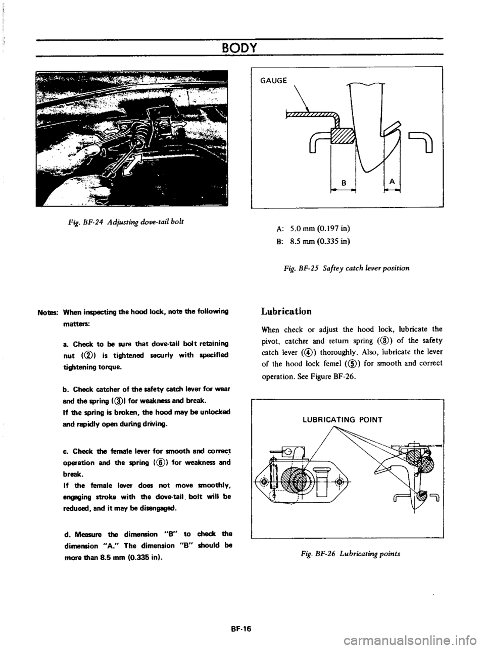
Fig
BF
24
Adjusting
dove
tail
bolt
Notes
When
inspecting
the
hood
lock
note
the
following
a
Check
to
be
sure
that
dove
tail
bolt
retaining
nut
VI
is
tightened
securly
with
specified
tightening
torque
b
Check
catcher
of
the
safety
catch
lever
for
wear
and
the
spring
ID
I
for
weakness
and
break
If
the
spring
is
broken
the
hood
may
be
unlocked
and
rapidly
open
during
driving
c
Check
the
female
lever
for
smooth
and
conect
operation
and
the
spring
@
for
weakness
and
break
If
the
female
lever
does
not
mova
smoothly
angaging
stroka
with
tha
dove
tail
bolt
will
ba
reduced
and
it
may
be
disengaged
d
Measure
the
di
S6
to
check
the
dimension
A
The
dimension
B
should
be
mora
than
8
5
mm
10
335
in
BF
16
GAUGE
r
B
A
A
5
0
mm
0
197
in
B
8
5
mm
0
335
in
Fig
BF
25
Saftey
catch
ever
position
Lubrication
When
check
or
adjust
the
hood
lock
lubricate
the
pivot
catcher
and
return
spring
ID
of
the
safety
catch
lever
@
thoroughly
Also
lubricate
the
lever
of
the
hood
lock
femel
ID
for
smooth
and
correct
operation
See
Figure
BF
26
LUBRICATING
POINT
Fig
BF
26
Lubricating
points
Page 207 of 513

BODY
FRONT
FENDER
AND
FRONT
END
CONTENTS
FRONT
FENDER
Removal
FRONT
BUMPER
BF
17
BF
17
BF
18
FRONT
FENDER
i
RADIATOR
GRILLE
OUTSIDE
MIRROR
BF
18
BF18
1
Front
fender
2
Cowl
top
sealer
3
Front
fender
sealer
4
Cowl
top
5
Side
dash
board
6
Front
pillar
7
Front
bumper
8
Front
bumper
stay
9
Front
bumper
side
bracket
10
Bumper
side
bracket
shim
Removal
Fig
BF
27
Front
fender
and
front
end
components
I
Open
the
hood
disconnect
the
battery
terrninal
for
the
sake
of
safety
and
disconnect
wirings
for
the
head
lamp
and
side
marker
lamp
at
their
connecting
terminals
2
Remove
the
front
bumper
radiator
grille
and
radiator
grille
surround
3
Remove
the
sm
moulding
and
holding
the
fender
remove
it
Fig
BF
28
Removing
front
fender
I
BF
17
Page 221 of 513

Installation
Install
the
door
glass
and
regulator
in
reverse
sequence
of
removal
Reinstall
the
seal
screen
after
correctly
adjusting
door
window
closing
SIDE
WINDOW
Removal
I
Remove
the
lock
pillar
moulding
and
remove
the
side
window
handle
set
screws
from
the
body
side
2
Loosen
the
side
window
hinge
installation
screws
and
remove
the
side
window
BODY
7
I
I
I
c
t
2
3
Side
window
glass
Side
window
hinge
Side
hinge
cover
4
Side
window
handle
5
Handle
shim
6
Catch
handle
bracket
Fig
BF
59
Side
window
construction
WINDSHIELD
AND
REAR
WINDOW
CONTENTS
REMOVAL
INSTAllATION
REAR
WINDOW
ELECTRIC
DEFROSTER
Option
SF
31
SF
32
SF
33
REMOVAL
1
Place
a
protective
cover
over
the
hood
front
fenders
instrument
panel
and
front
seat
2
Remove
rear
view
mirror
support
3
Remove
windshield
wiper
arm
assembly
4
On
inside
of
body
loosen
the
lip
of
the
rubber
channel
from
spot
welded
flange
along
the
top
and
sides
of
windshield
opening
With
the
palm
of
the
hand
apply
pressure
to
glass
near
edge
At
the
same
time
use
a
blunt
putty
knife
or
other
suitable
tool
and
carefully
assist
rubber
channel
over
spot
welded
flange
5
After
windshield
rubber
channel
is
free
from
spot
welded
flange
with
aid
of
helper
carefully
lift
windshield
assembly
frorn
body
opening
and
place
it
on
a
protected
bench
Removal
and
installation
Specifications
I
nspection
and
repair
WATERlEAK
CORRECTION
BF
34
SF
34
SF
34
SF
36
Fig
BF
60
Removing
windshield
Note
The
windshield
chrome
moulding
are
installed
in
the
rubber
channel
and
should
be
removed
prior
to
removing
rubber
channel
from
the
gla55
SF
31
Page 325 of 513
ENGINE
Caution
lock
the
front
and
rear
wheels
by
fully
pulling
the
parking
brake
lever
before
con
ducting
this
test
Fig
ET
32
Checking
for
operation
of
vacuum
advance
system
If
any
objection
is
found
by
the
check
mentioned
above
either
of
the
following
defects
may
be
the
cause
Poor
connection
or
broken
harness
and
fuse
2
Air
leakage
resulting
from
poor
connection
of
vacu
um
tube
3
Incorrect
operation
of
Top
switch
4
Defective
operation
of
vacuum
cutting
valve
sole
naid
5
Incorrect
operation
of
thermo
switch
Testing
of
Top
switch
1
Make
sure
of
insulation
between
lead
wire
terminal
of
transmission
switch
and
switch
body
2
Disconnect
lead
wires
at
the
switch
and
connect
ohmmeter
to
tenninals
3
Ohmmeter
should
indicate
infmity
co
when
shift
lever
is
in
Top
gear
position
And
it
should
indicate
zero
at
other
gear
position
including
Neutral
posi
tion
4
If
it
does
not
work
properly
in
step
3
replace
the
switch
with
a
new
one
Testing
of
thermo
switch
I
MaJ
e
sure
of
insulation
between
lead
wire
terminal
of
thermo
switch
and
thetmo
switch
body
2
Disconnect
lead
wire
at
switch
and
connect
ohm
meter
to
terminals
Ohmmeter
should
indicate
zero
when
temperature
indicate
the
passenger
compartment
is
above
l30C
550F
4
If
it
does
not
work
properly
in
step
3
replace
thermo
switch
with
a
new
one
AUTOMATIC
TEMPERATURE
CONTROL
AIR
CLEANER
A
T
C
AIR
CLEANER
Replacing
carburetor
air
cleaner
filter
The
paper
element
viscous
type
has
been
specially
treated
to
eliminate
bother
of
cleaning
until
replacement
It
should
be
replaced
with
a
new
one
at
regular
intervals
or
more
often
according
to
the
operating
conditions
Checking
hot
air
control
valve
Inspection
Among
the
possible
troubles
of
this
device
the
most
liable
is
the
permanent
opening
of
valve
This
trouble
is
not
noticed
in
warm
weather
but
in
cold
weather
appears
as
poor
performance
of
engine
such
as
tardy
acceleration
hesitation
or
engine
stall
In
such
case
first
inspect
this
device
before
checking
the
carburetor
Another
trouble
which
might
be
expected
is
that
the
underhood
air
is
kept
closed
by
the
valve
regardless
of
the
temperature
of
suction
air
around
the
sensor
while
the
engine
is
running
This
ttOuble
appears
in
the
form
of
extremely
excessive
fuel
consumption
or
decrease
in
power
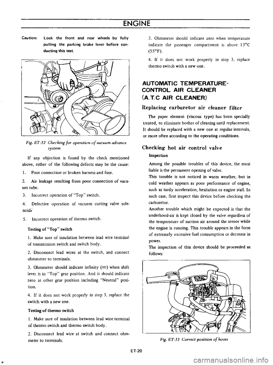
The
inspection
of
this
device
should
be
proceeded
as
follows
Fig
ET
33
Correct
position
of
hoses
ET
20
Page 326 of 513
EMISSION
CONTROL
AND
TUNE
UP
Appearance
1
First
inspect
whether
vacuum
hoses
are
connected
to
correct
positions
2
Inspect
hoses
for
cracks
distortion
or
plugging
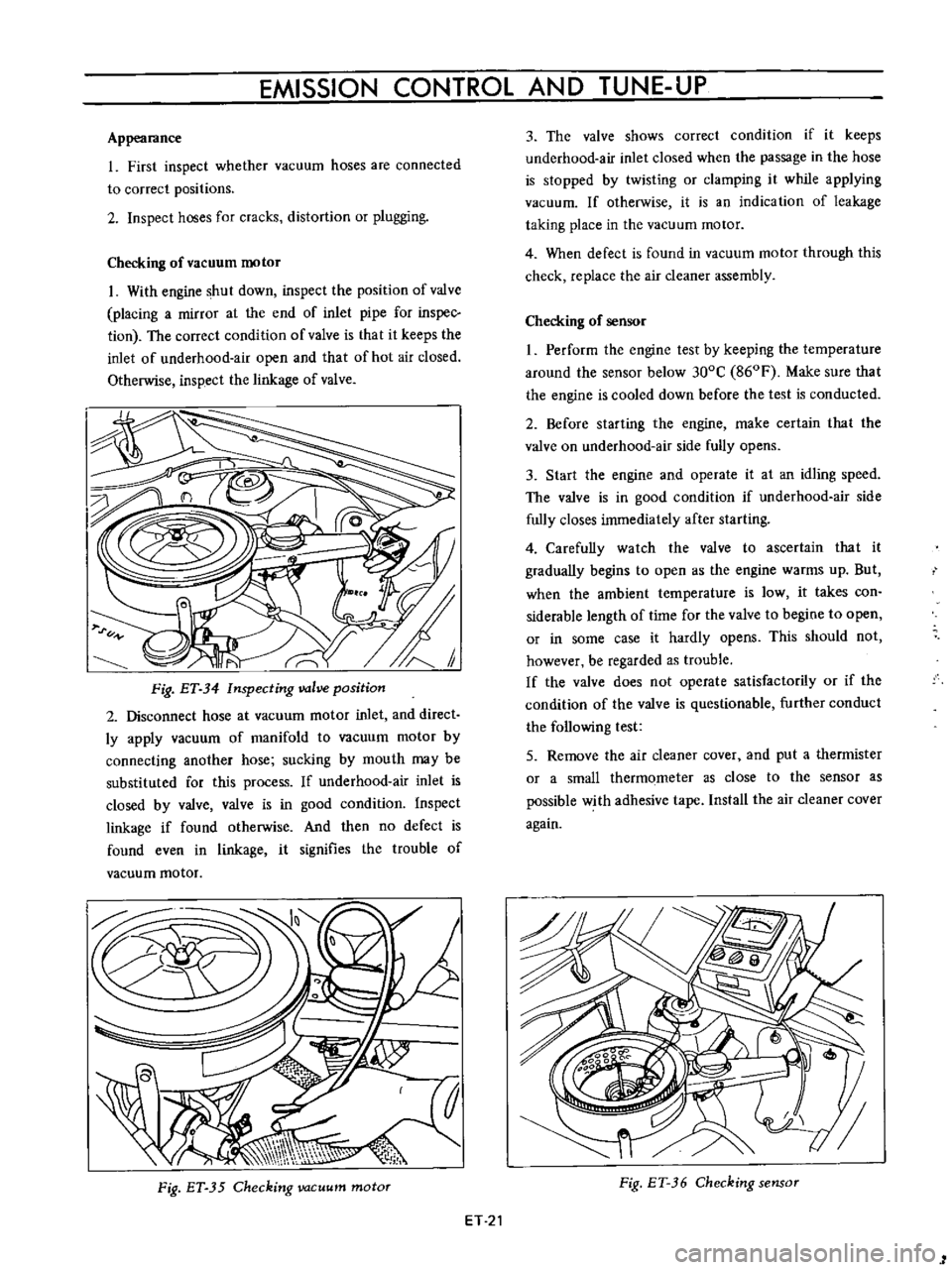
Checking
of
vacuum
motor
I
With
engine
shut
down
inspect
the
position
of
valve
placing
a
mirror
at
the
end
of
inlet
pipe
for
inspec
tion
The
correct
condition
of
valve
is
that
it
keeps
the
inlet
of
underhood
air
open
and
that
of
hot
air
closed
Otherwise
inspect
the
linkage
of
valve
Fig
ET
34
Inspecting
valve
position
2
Disconnect
hose
at
vacuum
motor
inlet
and
direct
ly
apply
vacuum
of
manifold
to
vacuum
motor
by
connecting
another
hose
sucking
by
mouth
may
be
substituted
for
this
process
If
underhood
air
inlet
is
closed
by
valve
valve
is
in
good
condition
Inspect
linkage
if
found
otherwise
And
then
no
defect
is
found
even
in
linkage
it
signifies
the
trouble
of
vacuum
motor
Fig
ET
35
Checking
vacuum
motor
ET
21
3
The
valve
shows
correct
condition
if
it
keeps
underhood
air
inlet
closed
when
the
passage
in
the
hose
is
stopped
by
twisting
or
clamping
it
while
applying
vacuum
If
otherwise
it
is
an
indication
of
leakage
taking
place
in
the
vacuum
motor
4
When
defect
is
found
in
vacuum
motor
through
this
check
replace
the
air
cleaner
assembly
Checking
of
sensor
I
Perform
the
engine
test
by
keeping
the
temperature
around
the
sensor
below
300C
860F
Make
sure
that
the
engine
is
cooled
down
before
the
test
is
conducted
2
Before
starting
the
engine
make
certain
that
the
valve
on
underhood
air
side
fully
opens
3
Start
the
engine
and
operate
it
at
an
idling
speed
The
valve
is
in
good
condition
if
underhood
air
side
fully
closes
immediately
after
starting
4
Carefully
watch
the
valve
to
ascertain
that
it
gradually
begins
to
open
as
the
engine
warms
up
But
when
the
ambient
temperature
is
low
it
takes
con
siderable
length
of
time
for
the
valve
to
begine
to
open
or
in
some
case
it
hardly
opens
This
should
not
however
be
regarded
as
trouble
If
the
valve
does
not
operate
satisfactorily
or
if
the
condition
of
the
valve
is
questionable
further
conduct
the
following
test
5
Remove
the
air
cleaner
cover
and
put
a
thermister
or
a
small
thermometer
as
close
to
the
sensor
as
possible
with
adhesive
tape
Install
the
air
cleaner
cover
again
Fig
ET
36
Checking
sensor
1
Page 394 of 513
FUEL
SYSTEM
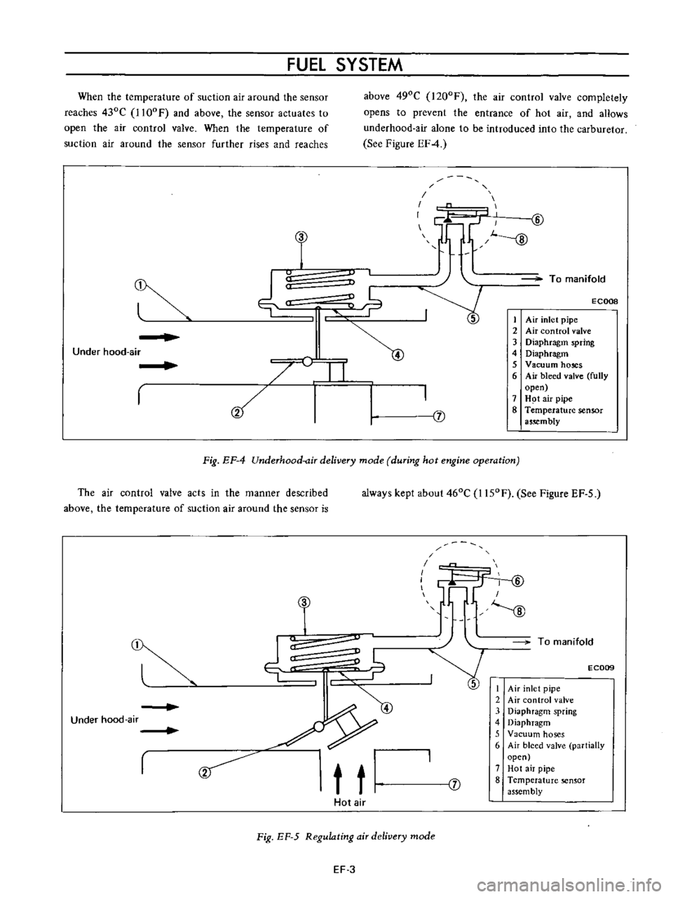
When
the
temperature
of
suction
air
around
the
sensor
reaches
430C
1l00F
and
above
the
sensor
actuates
to
open
the
air
control
valve
When
the
temperature
of
suction
air
around
the
sensor
further
rises
and
reaches
above
490C
I200F
the
air
control
valve
completely
opens
to
prevent
the
entrance
of
hot
air
and
aHows
underhood
air
alone
to
be
introduced
into
the
carburetor
See
Figure
EF4
u
C
I
1f1
lL
GJ
J
To
manifold
ECOOB
j
1
Air
inlet
pipe
2
Air
control
valve
3
Diaphragm
spring
4
Diaphragm
5
Vacuum
hoses
6
Air
bleed
valve
fully
open
7
H
t
air
pipe
8
Temperature
sensor
a5
mbly
Under
hood
air
I
I
Fig
EF
4
Underhood
air
delivery
mode
during
hot
engine
operation
The
air
control
valve
acts
in
the
manner
described
above
the
temperature
of
suction
air
around
the
sensor
is
always
kept
about
460C
I150F
See
Figure
EF
5
r
9
t
t
T
I
I
I
fY
ID
I
J
To
manifold
E
C009
I
Air
inlet
pipe
2
Air
control
valve
3
Diaphragm
spring
4
Diaphragm
5
Vacuum
hoses
6
Air
bleed
valve
partially
open
7
Hot
air
pipe
8
Temperature
sensor
assembly
Under
hood
air
J
Hot
air
Fig
EF
5
Regulating
air
delivery
mode
EF
3
Page 395 of 513
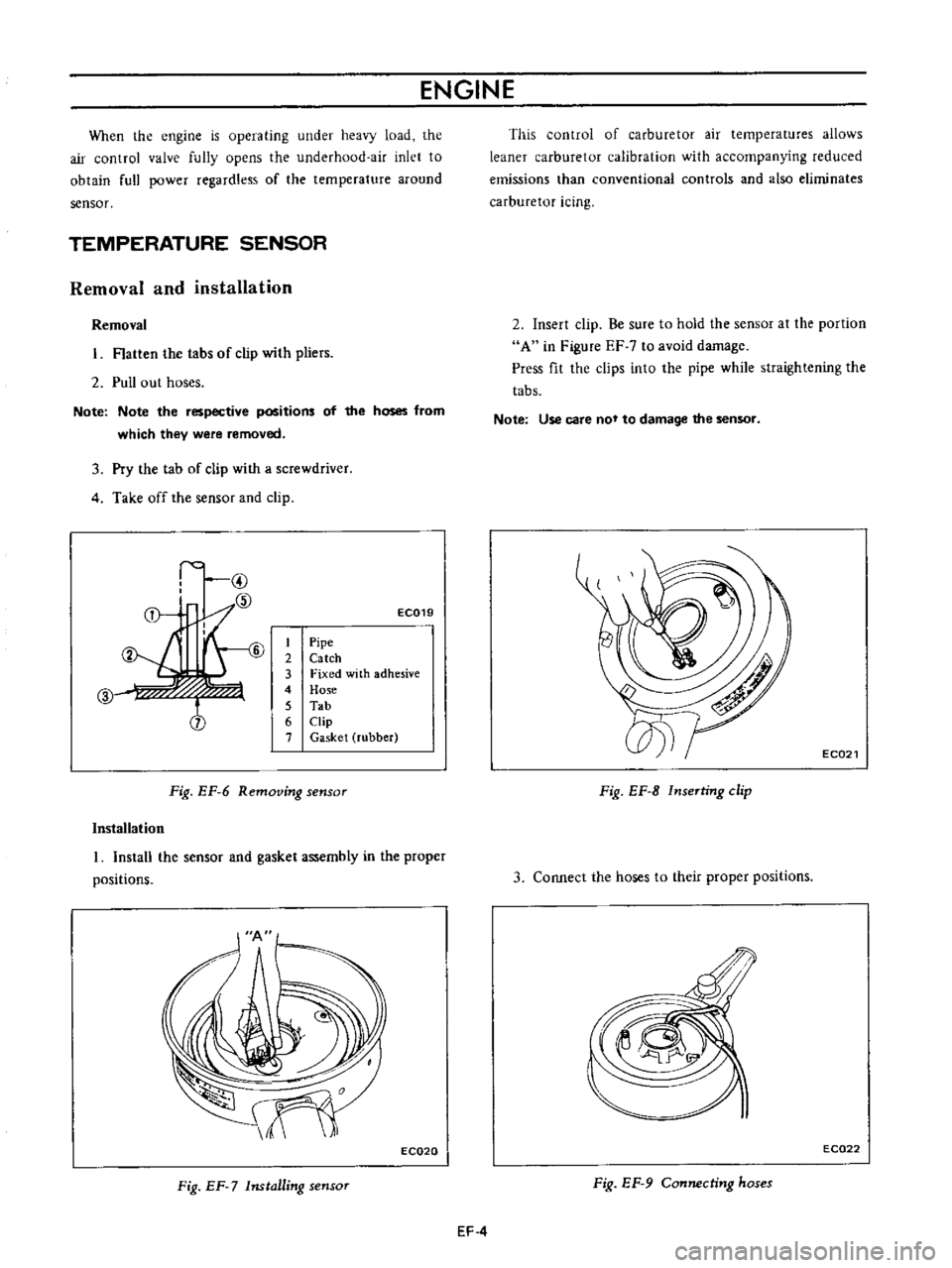
ENGINE
When
the
engine
is
operating
under
heavy
load
the
air
control
valve
fully
opens
the
underhood
air
inlet
to
obtain
full
power
regardless
of
the
temperature
around
sensor
TEMPERATURE
SENSOR
Removal
and
installation
Removal
Hatten
the
tabs
of
clip
with
pliers
2
Pull
out
hoses
Note
Note
the
respective
positions
of
the
hoses
from
which
they
were
removed
3
Pry
the
tab
of
clip
with
a
screwdriver
4
Take
off
the
sensor
and
clip
I
@
f
6
7
CID
f
j
EC019
1
Pipe
2
Catch
3
Fixed
with
adhesive
4
Hose
5
Tab
6
Clip
7
Gasket
rubber
Fig
EF
6
Removing
sensor
Installation
I
Install
the
sensor
and
gasket
assembly
in
the
proper
positions
EC020
Fig
EF
7
Installing
sensor
This
control
of
carburetor
air
temperatures
allows
leaner
carburetor
calibration
with
accompanying
reduced
emissions
than
conventional
controls
and
also
eliminates
carburetor
icing
2
Insert
clip
Be
sure
to
hold
the
sensor
at
the
portion
A
in
Figure
EF
7
to
avoid
damage
Press
fit
the
clips
into
the
pipe
while
straightening
the
tabs
Note
Use
care
not
to
damage
the
sensor
EC021
Fig
EF
B
InseTting
clip
3
COIUlect
the
hoses
to
their
proper
positions
EC022
Fig
EF
9
Connecting
hoses
EF
4
Page 467 of 513

CHASSIS
ENGINE
REMOVAL
AND
INSTALLATION
CONTENTS
PR
ECAUTIONS
REMOVAL
ERA
ERA
PRECAUTIONS
Be
sure
to
use
fender
cover
so
that
the
body
is
not
damaged
2
When
lifting
the
engine
or
when
jacking
up
the
engine
pay
attention
for
safety
and
carry
out
operation
correctly
so
that
the
parts
are
not
damaged
REMOVAL
I
Removing
hood
Open
the
hood
remove
four
installation
bolts
and
remove
the
hood
2
Disconnect
the
battery
cable
from
the
terminal
3
Removing
radiator
Drain
water
from
the
radiator
disconnect
two
radiator
hoses
remove
four
radiator
installation
bolts
and
remove
the
radiator
Fig
ER
8
Removin
radiator
4
Removing
cables
and
hoses
Disconnect
the
following
cables
hoses
and
wires
High
voltage
cable
between
ignition
coil
and
distribu
INSTAllATION
ER
6
tor
Cable
to
the
thermal
transmitter
Cable
to
the
oil
pressure
switch
Cable
to
the
primary
side
of
the
distributor
Cable
to
the
starting
motor
Fuel
hose
Cable
to
the
alternator
Heater
hose
for
model
with
heater
only
Wires
for
accelerator
and
choke
The
operation
will
be
carried
out
more
easily
by
removing
the
air
cleaner
Fig
ER
9
Right
side
of
engine
compartment
Fig
ER
10
Left
side
of
engine
compartment
ERA