1973 DATSUN B110 engine coolant
[x] Cancel search: engine coolantPage 55 of 513

c
Inspection
and
adJu
Stmenf
trouble
first
check
the
linhge
f
no
1
i
jI
fect
is
found
in
the
lin1
age
check
of
manu
a
l
liiiJ
i
the
inhibitor
switch
Th
d
1F
aI
S
t
th
I
I
f
e
a
JU
i
J
u
epara
e
e
range
se
eet
ever
rom
Iy
important
ii
s3
ns
etion
of
oil
the
lower
shift
rod
and
turn
the
range
1
level
for
the
automatiC
tran
smission
select
lever
to
N
Therefore
great
care
should
be
exer
Note
In
the
position
N
the
slot
of
cised
because
defective
adjustment
will
the
manual
shaft
is
vertical
result
in
the
breakdown
of
the
trans
By
the
use
of
the
tester
check
the
two
bIack
yellow
BY
wires
from
the
inhibitor
switch
in
the
ranges
N
and
P
and
the
two
red
bIack
RB
wires
in
the
range
R
for
continuity
Turn
range
select
lever
to
both
directions
from
each
lever
set
position
and
check
each
continuity
range
It
is
normal
if
the
electricity
is
on
while
the
lever
is
within
an
angle
of
about
3
0
on
both
sides
from
each
lever
set
line
How
ever
if
its
continuity
range
is
obvi
ously
unequal
on
both
sides
the
adjustment
is
required
f
any
malfunction
is
found
un
screw
the
fastening
nut
of
the
range
selector
lever
and
two
fastening
bolts
of
the
switch
body
and
then
remove
the
machine
screw
under
the
switch
body
Adjust
the
manual
shaft
correct
ly
to
the
position
N
by
means
of
the
selector
lever
When
the
slot
of
the
shaft
becomes
vertical
the
detent
works
to
position
the
shaft
correctly
with
a
click
sound
Move
the
switch
slightly
aside
so
that
the
screw
hole
will
be
aligned
with
the
pin
hole
of
the
internal
rotor
combined
with
the
manual
shaft
and
check
their
alignment
by
inserting
a
1
5
0101
0
0591
in
diameter
pin
into
the
holes
If
the
alignment
is
made
correct
1
5ten
the
switch
body
with
the
bolts
pull
out
the
pin
and
tighten
up
the
screw
again
into
the
hole
and
fasten
the
selector
lever
as
before
Check
over
again
the
continuity
with
the
tester
If
the
malfunction
still
remains
replace
the
inhibitor
switch
mission
Inspection
Pull
the
selector
lever
toward
you
and
turn
it
so
far
as
p
to
1
range
where
clicks
will
be
felt
by
hand
This
is
the
detent
of
manual
valve
in
the
body
and
indicates
the
correct
posi
tion
of
the
lever
Inspect
whether
the
pointer
of
selector
dial
corresponds
to
this
point
and
also
whether
the
lever
comes
in
alignment
with
the
stepping
of
posi
tion
plate
when
it
is
released
Adjustment
This
procedure
can
be
accom
plished
by
referring
to
Removal
and
nstallation
Checking
and
adjusting
inhibitor
switch
The
inhibitor
switch
serves
to
light
the
reverse
lamp
in
the
range
R
of
the
transmission
operation
and
also
to
rotate
the
starter
motor
in
the
ranges
N
and
P
j
r@
I
If
r
f
B
@
I
Jt
@
@
c
v@
i
r
fji
AT109
1
Inhibitor
switch
2
Manual
shaft
3
Washer
4
Nut
5
Manual
plate
Fig
AT
II
0
Con
truction
of
inhibitor
witch
6
Washer
7
Nut
8
Inhibitor
switch
9
Range
select
lever
Check
whether
the
reverse
lamp
and
the
starter
motor
operate
normal
ly
in
these
ranges
If
there
is
any
t
ki
A
mm
ATIC
TRANSMISSION
STALL
TEST
The
purpose
of
this
test
is
to
check
the
transmission
and
engine
for
trou
ble
by
measuring
the
maximwn
num
bers
of
revolutions
of
the
engine
while
vehicle
is
held
in
a
stalled
condition
and
the
carburetor
is
in
full
throttle
operation
with
the
selector
lever
in
AT
51
rang
s
D
2
and
I
respectively
and
by
com
pairing
the
measured
re
sults
with
the
standard
values
Standard
stall
revolution
1
750
to
2
000
rpm
Components
to
be
tested
and
test
items
1
Clutches
brake
and
band
in
trans
mission
for
slipping
2
Torque
converter
for
function
3
Engine
for
overall
property
Stall
test
procedures
Before
testing
check
the
enigne
oil
and
torque
converter
oil
warm
up
the
engine
cooling
water
to
the
suitable
temperature
by
warming
up
ope
ration
at
1
200
rpm
with
the
selector
lever
in
the
range
P
for
several
minutes
and
warm
up
the
torque
converter
oil
to
the
suitable
temperature
60
to
IOOoC
140
to
2120F
1
Mount
the
engine
tachometer
at
a
location
that
allows
good
visibility
from
the
driver
s
seat
and
put
a
mark
on
specified
revolutions
on
the
meter
2
Secure
the
front
and
rear
wheels
completely
with
chocks
and
apply
the
hand
brake
Be
sure
to
depress
the
brake
pedal
firmly
with
the
left
foot
before
depressing
down
the
accelerator
pedal
3
Throw
the
selector
lever
into
the
range
D
4
Slowly
depress
the
accelerator
pedal
down
till
the
throttle
valve
is
fully
opened
Quickly
read
and
record
the
engine
revolution
when
the
engine
begins
to
rotate
steadily
and
then
release
the
accelerator
pedal
5
Turn
the
selector
lever
into
N
and
operate
the
enigne
at
approxi
mately
1
200
rpm
for
more
than
one
minute
to
cool
down
the
torque
con
verter
oil
and
coolant
6
Make
similar
stall
tests
in
the
ranges
2
I
and
R
Note
The
stall
test
operation
as
spec
ified
in
the
item
4
should
be
made
within
five
seconds
If
it
takes
too
long
the
oil
deterio
rates
and
the
clutches
brake
Page 302 of 513

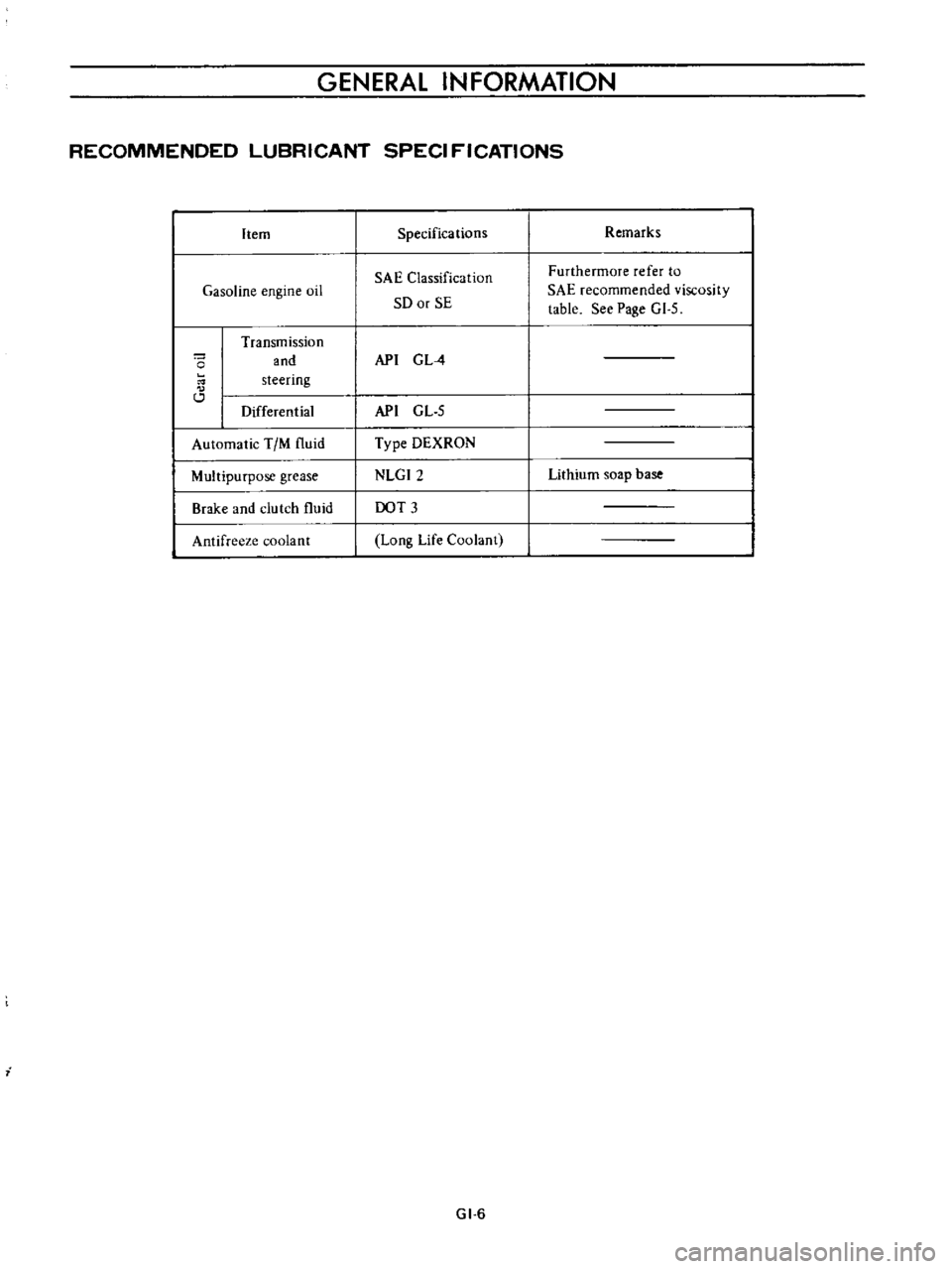
GENERAL
INFORMATION
RECOMMENDED
LUBRICANT
SPECI
FICATIONS
Item
Gasoline
engine
oil
o
Transmission
and
steering
Differential
Automatic
TIM
fluid
Multipurpose
grease
Brake
and
clutch
fluid
Antifreeze
coolant
i
Specifications
SAE
Classification
SO
or
SE
API
G
L
4
API
GL
5
Type
DEXRON
NLGI2
DOT
3
Long
Life
Coolant
GI
6
Remarks
Furthermore
refer
to
SAE
recommended
viscosity
table
See
Page
GI
5
Lithium
soap
base
Page 303 of 513

GENERAL
INFORMATION
NISSAN
LONG
LIFE
COOLANT
L
L
C
The
cooling
system
has
been
filled
at
factory
with
the
Long
Life
Coolant
L
L
C
and
water
for
aU
season
protection
This
coolant
provides
freezing
protection
to
150C
50F
in
a
30
Long
Life
Coolant
ratio
and
also
protects
the
engine
against
corrosion
If
outside
tempera
ture
falls
down
to
350C
3IOF
fill
a
50
50
mixture
of
the
Long
Life
Coolant
and
water
The
Long
Life
Coolant
is
an
ethylene
glycol
base
product
containing
any
glyc
erine
ethyl
or
methyl
alcohoL
The
Long
Life
Coolant
must
not
be
mixed
with
any
other
product
scale
nor
sediment
accumulated
in
water
jacket
or
radiator
adverse
ly
affects
heat
radiation
efficiency
When
the
coolant
is
changed
the
system
should
be
thoroughly
flushed
out
by
opening
the
two
drain
plugs
one
at
the
bottom
of
the
radiator
and
the
other
at
the
left
side
of
the
cylinder
block
until
clean
water
comes
out
Always
use
clean
soft
water
in
the
radiator
for
filling
the
radiator
DC
OF
01321
30
1
221
I
I
I
I
1
I
I
I
10
20
30
40
50
10
14
20
1
4
40
1
401
50
581
Fig
GI
13
Protection
concentration
Boiling
point
Percent
0
9
kg
cm2
Freeze
coneen
Sea
level
cooling
sys
protection
tratioo
tern
pressure
30
1060C
1240C
15OC
2210
F
2550
F
5OF
50
1090C
1270C
350C
2280
F
26IOF
3IOF
SERVICE
JOURNAL
OR
BULLETIN
REFERENCE
DATE
JOURNAL
or
BULLETIN
No
PAGE
No
SUBJECT
GI
7
Page 306 of 513

EMISSION
CONTROL
AND
TUNE
UP
EMISSION
CONTROL
SYSTEM
AN
D
ENGINE
TUNE
UP
CONTENTS
BASIC
MECHANICAL
SYSTEM
ET
Checking
and
adjusting
dash
pot
Adjusting
intake
and
exhaust
valve
automatic
transmission
model
only
ET
9
clearances
ET
1
Checking
carburetor
return
spring
ET
9
Checking
and
adjustin9
drive
belt
ET
2
Checking
choke
mechanism
choke
valve
Retightening
cylinder
head
bolts
manifold
and
linkagel
ET
9
nuts
and
carburetor
securing
nuts
ET
2
Checking
anti
dieseling
solenoid
ET
9
Checking
engine
oil
ET
2
Replacing
fuel
filter
ET
10
Replacing
oil
filter
ET
3
Checking
fuel
lines
hoses
pipings
Changing
engine
coolant
L
L
C
ET
3
connections
etc
ET10
Checking
cooling
system
hoses
and
THROTTLE
OPENER
CONTROL
SYSTEM
ET
10
connections
ET
4
Checking
and
adjusting
throttle
opener
ET
13
Checking
vacuum
fittings
hoses
and
TRANSMISSION
CONTROLLED
VACUUM
connections
ET
4
ADVANCE
SYSTEM
ET
17
Checking
engine
compression
ET
4
Checking
electrical
advance
control
system
ET
19
Checking
exhaust
manifold
heat
control
AUTOMATIC
TEMPERATURE
CONTROL
AIR
valve
ET
5
CLEANER
A
T
C
AIR
CLEANER
ET
20
IGNITION
AND
FUEL
SYSTEM
ET
5
Replacing
carburetor
air
cleaner
filter
ET
20
Checking
battery
ET
5
Checking
hot
air
control
valve
ET
20
Checking
and
adjusting
ignition
timing
ET
5
CRANKCASE
EMISSION
CONTROL
Checking
or
replacing
distributor
breaker
SYSTEM
ET
22
point
condenser
and
spark
plugs
ET
6
Checking
or
replacing
PCV
valve
ET
23
Checking
distributor
ignition
wiring
and
Checking
ventilation
hoses
ET
23
ignition
coil
ET
7
EVAPORATIVE
EMISSION
CONTROL
Checking
distributor
cap
and
rotor
ET
7
SYSTEM
ET
23
Adjusting
carburetor
id
Ie
rpm
and
Checking
engine
compartment
hose
mixture
ratio
ET
8
connections
and
fuel
vapor
control
valves
ET
23
Checking
fuel
tank
vacuum
relief
valve
operation
ET
24
BASIC
MECHANICAL
SYSTEM
1
Start
engine
and
run
it
until
it
is
heated
to
operating
temperature
or
at
least
more
than
800C
I760F
of
engine
oil
temperature
then
stop
engine
Adjusting
intake
and
exhaust
valve
clearances
Valve
clearance
adjustment
should
be
made
while
engine
is
stationary
To
adjust
proceed
as
follows
2
Rotate
crankshaft
to
bring
No
1
cylinder
in
top
dead
center
on
its
compression
stroke
3
Remove
valve
rocker
cover
to
gain
access
to
valve
ET
1
Page 308 of 513

EMISSION
CONTROL
AND
TUNE
UP
Capacity
Maximum
3
3
L
X
US
gal
y
Imp
gal
2
3
L
US
gal
f
Imp
gal
Minimum
Make
sure
that
engine
oil
is
not
deteriorated
with
cooling
water
or
gasoline
Drain
and
refill
the
oil
if
necessary
Notes
a
A
milky
oil
indicates
the
presence
of
cooling
water
Find
the
cause
for
necessary
corrective
action
b
Oil
with
extremely
low
viscosity
indicates
dilution
with
gasoline
2
Check
oil
level
If
found
below
L
mark
refill
to
H
mark
on
gauge
Fig
ET
3
Checking
engine
oil
level
Replacing
oil
filter
The
oil
ftIter
is
of
a
cartridge
type
The
oil
filter
can
be
removed
using
oil
ftIter
wrench
STl9320000
Check
for
oil
leaks
through
gasketed
flange
If
any
leakage
is
found
retighten
slightly
If
necessary
replace
filter
as
an
assembly
2
When
installing
an
oil
filter
tighten
by
hand
Note
Do
not
overtighten
oil
filter
or
oil
leakage
way
result
Changing
engine
coolant
L
L
C
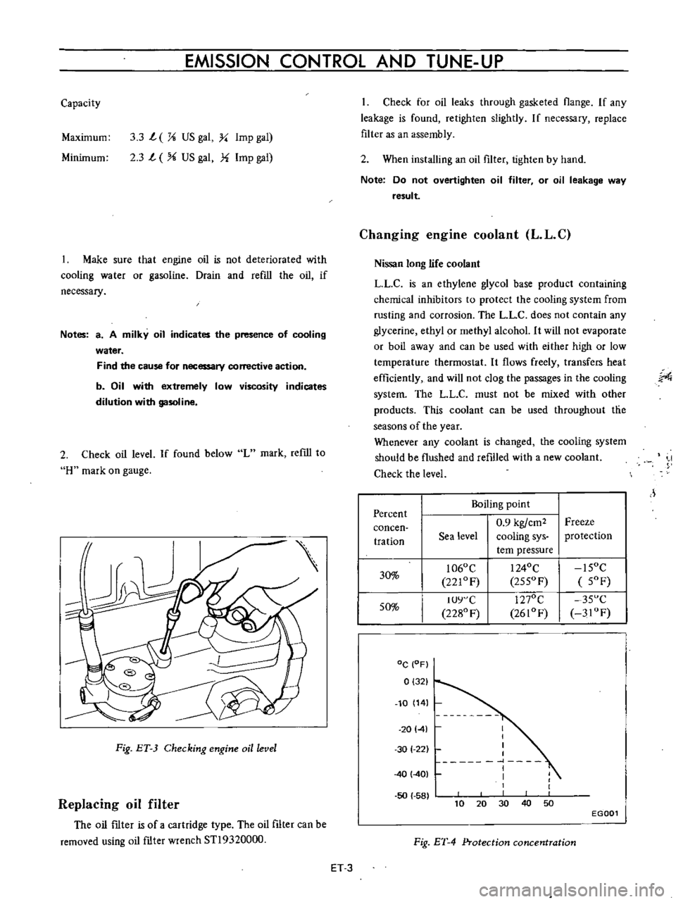
Nissan
long
life
coolant
LLC
is
an
ethylene
glycol
base
product
containing
chemical
inhibitors
to
protect
the
cooling
system
from
rusting
and
corrosion
The
L
L
C
does
not
contain
any
glycerine
ethyl
or
methyl
alcohol
It
will
not
evaporate
or
boil
away
and
can
be
used
with
either
high
or
low
temperature
thermostat
It
flows
freely
transfers
heat
efficiently
and
will
not
clog
the
passages
in
the
cooling
system
The
LL
C
must
not
be
mixed
with
other
products
This
coolant
can
be
used
throughout
tlie
seasons
of
the
year
Whenever
any
coolant
is
changed
the
cooling
system
should
be
flushed
and
refilled
with
a
new
coolant
Check
the
level
J
Percent
Boiling
point
0
9
kgfcm2
Freeze
concen
tration
Sea
level
cooling
sys
protection
tern
pressure
30
1060
C
I
240C
15OC
221OF
255OF
5OF
50
IUY
C
1270C
35
C
2280
F
2610F
3IOF
DC
OF
0
321
10
14
20141
50
58
I
I
I
I
1
I
I
1
30
1
22
40
401
40
10
30
50
20
EGOOl
Fig
ET
4
Protection
concentration
ET
3
Page 310 of 513

EMISSION
CONTROL
AND
TUNE
UP
reading
cylinders
through
spark
plug
hole
Repeat
compression
check
on
these
cylinders
1
If
compression
improves
considerably
piston
rings
are
defective
2
If
compression
does
not
improve
valves
are
sticking
or
seating
improperly
3
If
two
adjacent
cylinders
indicate
low
compression
and
injecting
oil
on
pistons
does
not
increase
compres
sion
the
cause
may
be
a
cylinder
head
gasket
leak
between
the
cylinders
Engine
oil
and
coolant
in
cylinder
could
result
from
this
problem
Compression
pressure
12
S
to
14
S
kg
cm2
178
to
206
psi
at
3S0
rpm
Checking
exhaust
manifold
heat
control
valve
Check
heat
control
valve
for
proper
operation
If
it
does
not
operate
properly
trouble
is
due
to
excess
carbon
on
shaft
or
damaged
shaft
Clean
if
necessary
The
bimetal
should
be
also
checked
for
proper
function
IGNITION
AND
FUEL
SYSTEM
Checking
battery
Check
electrolyte
level
in
each
battery
celL
L
Unscrew
each
filler
cap
and
inspect
fluid
leveL
If
fluid
level
is
low
add
distilled
water
to
bring
level
up
to
app
roximately
10
to
20
mm
0
3937
to
0
7874
in
above
plates
Do
not
overfilL
2
Measure
specific
gravity
of
battery
electrolyte
ET002
Fig
ET
B
Checking
the
specific
gravity
of
battery
electrolyte
Permissible
Full
charge
value
value
at
200C
68OF
Frigid
climates
Over
1
22
1
28
Tropical
climates
Over
1
18
1
23
Other
climates
Over
L
20
1
26
Clean
the
top
of
battery
and
terminals
with
a
solu
lion
of
baking
soda
and
water
Rinse
off
and
dry
with
compressed
air
The
top
of
battery
must
be
clean
to
prevent
current
leakage
between
terminals
and
from
positive
terminal
to
hold
down
clamp
In
addition
to
current
leakage
prolonged
accumulation
of
acid
and
dirt
on
the
top
of
battery
may
cause
blistering
of
the
material
covering
connector
straps
and
corrosion
of
straps
After
tightening
terminals
coat
them
with
petro
laturn
vaseline
to
protect
them
from
corrosion
Checking
and
adjusting
ignition
timing
I
Check
spark
plugs
and
distributor
breaker
points
for
condition
2
Thoroughly
wipe
off
dirt
and
dust
from
timing
marks
on
crank
pulley
and
front
cover
3
Warm
up
engine
sufficiently
ET
5
Page 335 of 513

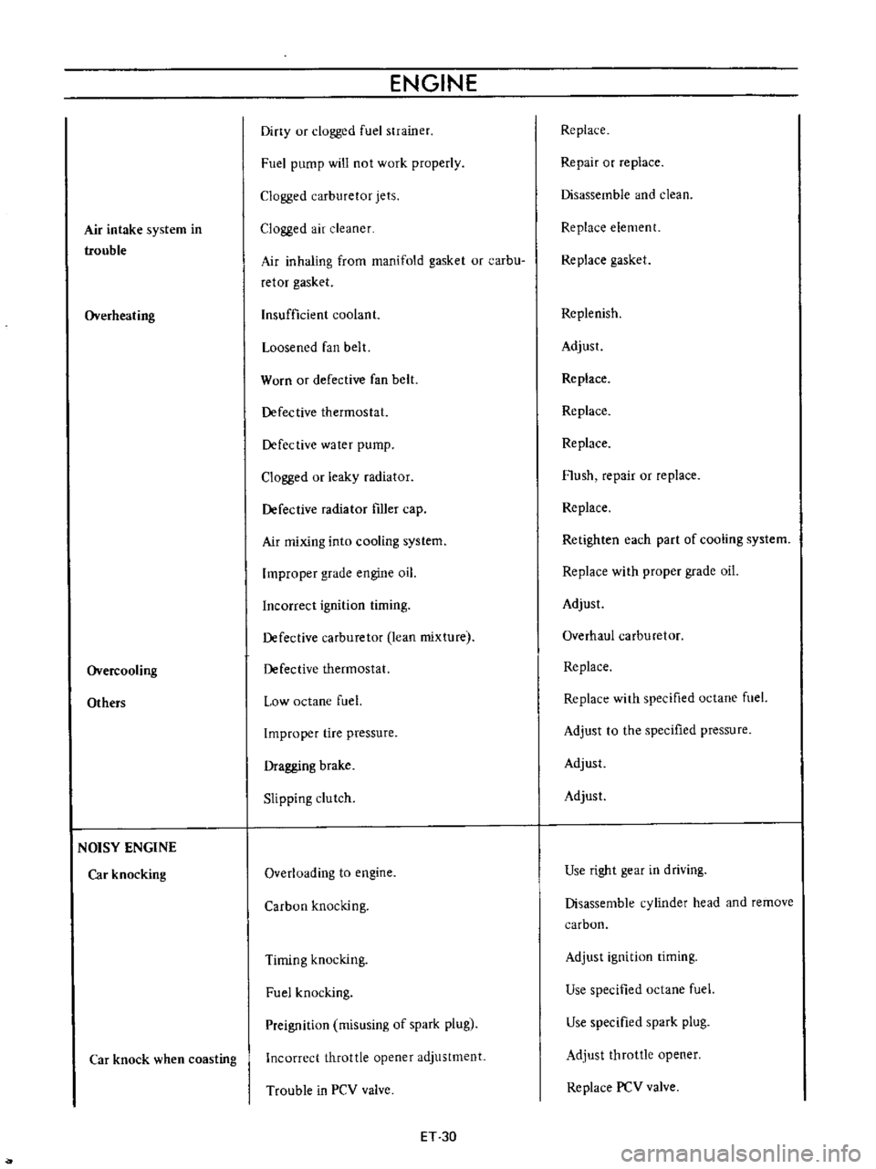
Air
intake
system
in
trouble
Overheating
Overcooling
Others
NOISY
ENGINE
Car
knocking
Car
knock
when
coasting
ENGINE
Diny
ur
clogged
fuel
strainer
Fuel
pump
will
not
work
properly
Clogged
carburetor
jets
Clogged
air
cleaner
Air
inhaling
from
manifold
gasket
or
carbu
retor
gasket
Insufficient
coolant
Loosened
fan
belt
Worn
or
defective
fan
belt
Defective
thermostat
Defective
water
pump
Clogged
or
leaky
radiator
Defective
radiator
filler
cap
Air
mixing
into
cooling
system
Improper
grade
engine
oil
Incorrect
ignition
timing
Defective
carburetor
lean
mixture
Defective
thermostat
Low
octane
fuel
Improper
tire
pressure
Dragging
brake
Slipping
clutch
Overloading
to
engine
Carbon
knocking
Timing
knocking
Fuel
knocking
Preignition
misusing
of
spark
plug
Incorrect
throttle
opener
adjustment
Trouble
in
PCV
valve
ET
30
Replace
Repair
or
replace
Disassemble
and
clean
Replace
element
Replace
gasket
Replenish
Adjust
Replace
Replace
Replace
Flush
repair
or
replace
Replace
Retighten
each
part
of
cooling
system
Replace
with
proper
grade
oil
Adjust
Overhaul
carburetor
Replace
Replace
with
specified
octane
fuel
Adjust
to
the
specified
pressure
Adjust
Adjust
Use
right
gear
in
driving
Disassemble
cylinder
head
and
remove
carbon
Adjust
ignition
timing
Use
specified
octane
fuel
Use
specified
spark
plug
Adjust
throttle
opener
Replace
PCV
valve
Page 388 of 513

ENGINE
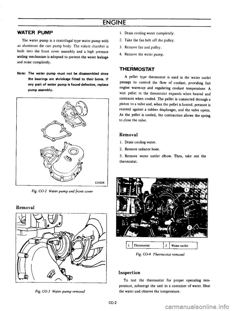
WATER
PUMP
The
water
pump
is
a
centrifugal
type
water
pump
with
an
aluminum
die
cast
pump
body
The
volute
chamber
is
built
into
the
front
cover
assembly
and
a
high
pressure
sealing
mechanism
is
adopted
to
prevent
the
water
leakage
and
noise
completely
Note
The
water
pump
must
not
be
disassembled
since
the
bearings
are
shrinkage
fitted
to
their
bores
If
any
part
of
water
pump
is
found
defective
replace
pump
assembly
o
C0026
Fig
CO
2
Water
pump
and
front
cover
Removal
Fig
CO
3
Water
pump
removal
Drain
cooling
water
completely
2
Take
the
fan
belt
off
the
pulley
3
Remove
fan
and
pulley
4
Remove
the
water
pump
THERMOSTAT
A
pellet
type
thermostat
is
used
in
the
wa
ter
outlet
passage
to
control
the
flow
of
coolant
providing
fast
engine
warm
up
and
regulating
coolant
temperature
A
wax
pellet
in
the
thermostat
expands
when
heated
and
contracts
when
cooled
The
pellet
is
connected
through
a
piston
to
a
valve
and
when
the
peUet
is
heated
pressure
is
exerted
against
a
rubber
diaphragm
and
the
valve
opens
As
the
pellet
is
cooled
the
contraction
allows
the
spring
to
close
the
valve
Removal
Drain
cooling
water
2
Remove
radiator
hose
3
Remove
water
outlet
elbow
Then
take
out
the
thermostat
11
I
Thermostat
12
Water
outlet
Fig
CO
4
Thermostat
removal
Inspection
To
test
the
thermostat
for
proper
operating
tern
perature
submerge
the
unit
in
a
container
of
water
Heat
the
water
and
observe
the
temperature
CO
2