1973 DATSUN B110 check oil
[x] Cancel search: check oilPage 13 of 513

Low
in
the
range
I
is
led
to
the
low
and
reverse
clutch
from
the
line
pressure
5
through
the
line
pressure
12
and
at
the
same
time
the
same
is
led
to
the
left
end
spring
unit
Consequently
although
the
go
vernor
pressure
increases
the
valve
is
still
depressed
toward
the
right
and
the
SFV
is
fixed
in
the
Low
posi
tion
When
kicked
down
at
the
2nd
speed
the
SDV
operates
and
the
line
pressure
13
depresse
the
FSV
to
ward
the
right
Although
the
governor
pressure
15
is
considerably
high
the
valve
is
depressed
completely
toward
the
right
and
the
FSV
is
returned
to
the
Low
position
This
operation
is
called
Kick
down
shift
2nd
3rd
shift
valve
SSV
The
SSV
is
a
transfer
vaIve
which
shifts
speed
from
2nd
to
3rd
When
the
vehicle
is
stopped
the
SSV
is
depressed
toward
the
right
by
the
spring
and
is
in
the
2nd
position
It
is
provided
however
that
the
FSV
decides
the
shifting
either
to
Low
or
2nd
When
the
vehicle
is
running
the
governor
pressure
15
is
applied
to
the
right
end
surface
and
the
SSV
is
depressed
toward
the
left
Contrarily
the
spring
force
line
pressure
3
and
throttle
pressure
19
depress
the
SSV
toward
the
right
When
the
vehicle
speed
exceeds
a
certain
level
the
governor
pressure
exceeds
the
sum
of
the
spring
force
line
pressure
and
throttle
pressure
the
valve
is
depressed
toward
the
left
and
the
line
pressure
3
is
closed
Conse
quently
the
forces
are
rapidly
un
balanced
the
force
to
depress
the
SSV
toward
the
right
reduces
and
thus
the
SSV
is
depressed
to
the
Ie
ft
end
for
a
moment
With
the
SSV
depressed
to
ward
the
left
end
the
line
pressure
3
is
connected
with
the
line
pressure
10
the
band
servo
is
released
the
front
clutch
is
engaged
and
speed
is
shifted
to
3rd
When
the
accelerator
pedal
is
de
pressed
both
the
line
pressure
3
and
the
throttle
pressure
19
are
high
and
AUTOMATIC
TRANSMISSION
therefore
the
SSV
is
retained
in
2nd
unless
ihe
governor
pressure
IS
exceeds
the
line
pressure
3
and
the
throttle
pressure
19
In
the
3rd
position
force
to
depress
the
SSV
toward
the
right
is
remained
only
on
the
throttle
pressure
16
and
the
throttle
pressure
16
is
slightly
lower
than
that
toward
the
right
which
is
applied
while
shifting
from
2nd
to
3rd
Consequently
the
SSV
is
returned
to
the
2nd
position
at
a
slightly
low
speed
side
Shifting
from
3rd
to
2nd
occurs
at
a
speed
slightly
lower
than
that
for
2nd
to
3rd
shifting
When
kicked
down
at
the
3rd
line
pressure
13
is
led
from
the
SDV
and
the
SSV
is
depressed
toward
the
right
Although
the
governor
pressure
is
considerably
high
the
valve
is
de
pressed
completely
toward
the
right
and
thus
the
SSV
is
returned
to
2nd
position
This
operation
is
called
Kick
down
shift
When
the
shift
lever
is
shifted
to
2
or
I
range
at
the
3rd
speed
the
line
pressure
3
is
drained
at
the
MNV
Consequently
the
front
clutch
operating
and
band
servo
releasing
oils
are
drained
As
the
res
lIt
the
trans
mission
is
shifted
to
the
2nd
or
low
speed
although
the
SSV
is
in
the
3rd
position
When
the
speed
is
shifted
to
the
3rd
a
one
way
orifice
24
on
the
top
of
the
SSV
relieves
oil
transmitting
velocity
from
the
line
pressure
3
to
the
line
pressure
10
and
reduces
a
shock
generated
from
the
shifting
Contrarily
when
shifted
from
3rd
to
2
or
range
and
the
speed
is
shifted
to
the
2nd
spring
of
the
orifice
24
is
depressed
the
throttle
becomes
ineffective
the
line
pressure
10
is
drained
quickly
and
thus
delay
in
the
speed
shifting
is
elimi
nated
Throttle
of
the
line
pressure
6
relieves
the
oil
transmitting
velocity
from
the
line
pressure
6
to
the
line
pressure
10
when
the
lever
is
shifted
to
the
R
range
and
relieves
drain
velocity
from
the
line
pressure
10
to
the
line
pressure
6
when
shifting
from
3rd
to
2nd
at
the
D
range
Thus
the
throttle
of
the
line
pressure
6
reduces
a
shock
generated
from
the
shifting
A
plug
in
the
SSV
left
end
readjust
the
throttle
pressure
16
which
varie
depending
on
the
engine
throttle
con
dition
to
a
throttle
pressure
19
suited
to
the
speed
change
control
Moreover
the
plug
is
a
valve
which
applies
line
pressure
13
in
lieu
of
the
throttle
pressure
to
the
SSV
and
the
FSV
when
kick
down
is
performed
When
the
throttle
pressure
16
is
applied
to
the
left
side
of
this
plug
and
the
plug
is
depressed
toward
the
right
a
slight
space
is
made
from
the
throttle
pressure
16
to
19
A
throt
tIe
pressure
19
which
is
lower
by
the
pressure
loss
equivalent
to
this
space
is
generated
the
pressure
loss
is
added
to
the
spring
force
and
thus
the
plug
is
depressed
back
from
the
right
to
the
left
When
this
pressure
19
increases
excessively
the
plug
is
further
de
pressed
toward
the
left
space
from
the
throttle
pressure
19
to
the
drain
circuit
13
increases
and
the
throttle
pressure
19
lowers
Thus
the
plug
is
balanced
and
the
throttle
pressure
19
is
reduced
in
a
certain
value
b
3
Orifice
t
checking
valve
24
15
2
2
i
I
1
c
V
Y
ii
pr
W
jt1
iff
I
W
q
I
nHH
J
L19
H
10
15
AT
9
A
T098
Fig
AT
13
2nd
3rd
shiflvalue
Page 23 of 513

AUTOMATIC
TRANSMISSION
UN
range
Neutral
Low
R
Brek
B
eke
B
x
12
VK
Th
o
I
V
lv
7
G
0
j
Lve
Fro
Lub
lc
l
Otifite
Check
Valve
D
alnValve
j
11
I
3
ThrOUle
OrOlln
Vah
f
11
J
l
8
5018
Back
up
g
Dow
ill
V
lv
V
v
P
Modif
V
lve
15
13
8Jlux
3
j
p
ssu
A
euleto
Velye
6
lL
2
Menuel
V
lv
iiJIN
NOI
M
ked
O
in
Lin
pre
lGovernor
teed
pr
e
Gove
no
pr
s
Torquecon
e
p
e5SU
ThroW
p
S
Ond
y
G
o
V
8
Primary
Goy
no
V
l
Fig
A
T
29
Oil
pressure
circuit
diagram
N
range
Neutral
AT
19
Page 25 of 513

AUTOMATIC
TRANSMISSION
D
range
Low
gear
To
queCon
t
Front
Clutch
LOW
R
B
B
k
B
I
12
I
3
L
12
U
J
I
IL
CID
Vecu
7
t
l
if
Valva
V
lv
TIC
Oil
Pr
r
0
i
Or
in
lV
I
F
Ofll
Lubf
lut
Orific
Check
V
lve
O
inV
Th
onl
O
ain
V
t
ll
Dow
thih
Solenoid
ID
Pt
Modifi
Valv
24
IS
@2nd
J
dShift
V
I
ll
12
3
ht
2nd
Ih
v
tv
S
j
P
Rev
I
IO
V
lv8
Menuel
V
lv
PRND21
NOle
Marked
O
ln
I
i
pres
00
0f
pressu
c
tI
I
GO
8
no
pre
aI
SKondary
Gov
no
V
To
q
econ
te
pr
s
Th
oUI
pt
Lmli
I
P
Irfw
a
ernor
V
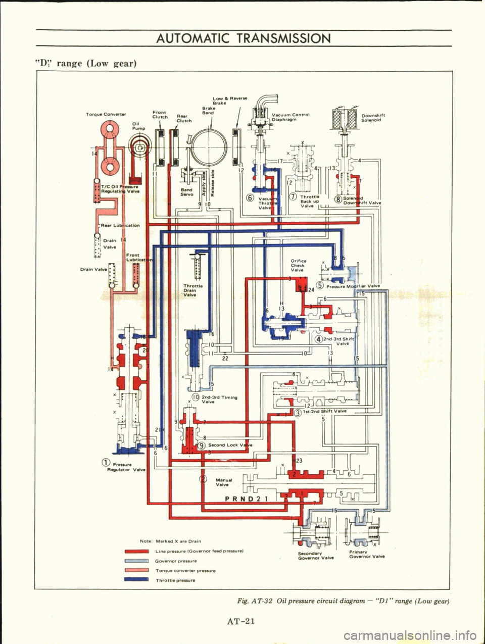
Fig
A
T
32
Oil
pressure
circuit
diagram
DJ
range
Low
gear
AT
21
Page 27 of 513

AUTOMATIC
TRANSMISSION
D
range
2nd
gear
Q
FrO
ll
Cluteh
Low
to
R
B
e
8
eke
Torque
Con
ert
14
Throttle
Beck
up
V
l
iftV
I
a
Q
T
COU
P
R
V
A
Lubfkatlon
11
Drain
14
V
I
l
CID
V
Thro
Valli
7
If
SOle
Wo
Front
Lubrlc
at
n
Orific
Check
V
I
OralnValw
Tt
oW
Q
aln
V
l
S
P
Modit
V
2
S
13
j
P
RIGulato
Vel
@2nd
3
dShIH
V
I
13
c
33J
2nd
ShlftV
I
e
s
Manual
V
I
n
NOla
M
ked
X
r
Drein
r
D
I
U
jeeo
v
Primarv
Gov
no
Valva
Goyarno
Val
Li
p
su
aIGo
no
IMod
pr
surel
Gov
nO
pr
sur
TO
Qu
con
pr
Th
on
p
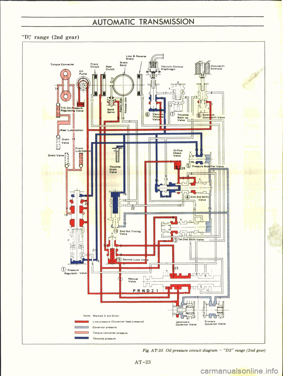
Fig
A
T
35
Oil
pressure
circuit
diagram
D2
range
2nd
gear
AT
23
Page 29 of 513

AUTOMATIC
TRANSMISSION
D
range
Top
gear
Low
r
Fl
B
e
B
e
B
14
TIC
Uil
Pr
1
v
Fl
Lubfk
tlon
O
ein
14
I
Velv8
l
Front
Lub
icet
Orlfiu
Check
V
I
8
6
13
@
2nd
3rd
Shifl
Velv
13
I
O
inV
Throttle
O
in
Ve
l
1
22
21
3
lit
2nd
Shift
Ve
5
M
V
I
5
n
NOle
M
ked
O
ein
Linep
s
Go
no
f
d
P
G
ernorp
Torqu
con
tt
p
secondary
G
norv
Ime
v
Governor
v
Th
Olt
p
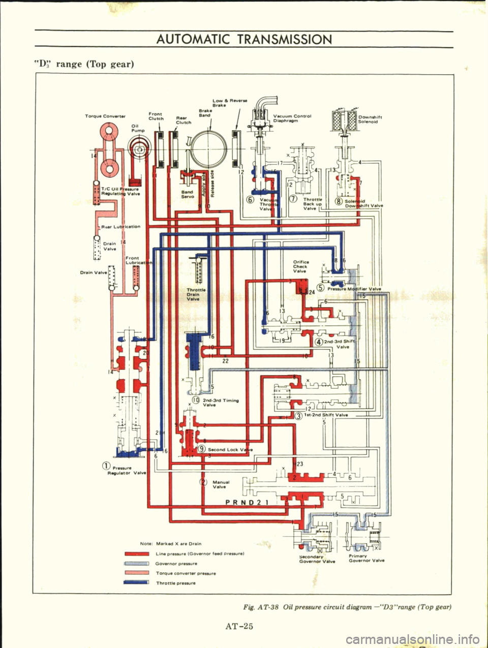
Fig
A
T
38
Oil
pressure
circuit
diagram
D3
range
Top
gear
AT
25
Page 31 of 513

AUTOMATIC
TRANSMISSION
I
ran
e
kick
down
shift
valves
in
2nd
gear
position
iQ
Front
ClutCh
L
llIR
B
ilk
8
e
Downshift
Solenoid
Torqu
Con
t
Q
I
Throttle
Back
up
V
lv
II
iftY
h
TIC
0
A
lV
A
Lubl
tion
e
S
lO
lID
VK
Th
o
I
V
v
8
Sol
Dow
Dr
I
V
I
F
lt
Lubrice
D
Yo
t
Otific
Check
0
Throttle
Dr
n
V
mm
OJ
12
Q
ht
2rod
hif
v
S
C
Ptenu
R
ul
to
Vel
8
Menu
0
PRND2
I
L
J
Jl
No
Me
klld
er
D
in
SKond
Prim
GO
no
0
1
Go
no
V
LIne
pr
s
100
0
l
d
p
1
Goy
rno
p
eslU
s
Torque
con
er
r
pr
Th
oUl
prnsu
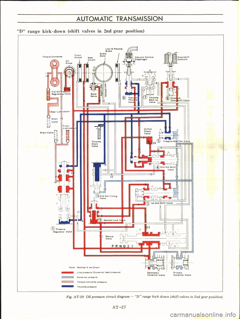
Fig
A
T
39
Oil
pressure
circuit
diagram
D
range
kick
down
shift
valves
in
2nd
gear
position
AT
27
Page 38 of 513

Fig
A
T
49
Torque
converter
aligning
cut
3
When
connecting
torque
con
verter
to
transmission
measure
dis
tance
A
to
be
certain
that
they
are
correctly
assembled
See
Figure
AT
50
Distance
A
More
than
16
5
IllIll
0
650
in
A
AT117
Fig
A
T
50
Installing
torque
converter
CHASSIS
4
Bolt
converter
to
drive
plate
Tightening
torque
0
8
to
1
0
kg
Ill
5
8
to
7
2
ft
Ib
Note
Align
chalk
marks
painted
a
cross
both
parts
during
disas
sembling
processes
5
After
converter
is
installed
rotate
crankshaft
several
turns
and
check
to
be
sure
that
transmission
rotates
freely
without
binding
6
Pour
recommended
automatic
transmission
fluid
up
to
correct
level
through
oil
charge
pipe
7
Connect
manual
lever
to
shift
rod
Operation
should
be
carried
out
with
manual
and
selector
levers
in
N
8
Connect
inhibitor
switch
wires
Notes
a
Refer
to
covering
topic
under
Checking
and
adjusting
inhibitor
switch
on
page
AT
51
b
Inspect
and
adjust
switch
as
above
whenever
it
has
to
be
removed
for
service
9
Check
inhibitor
switch
for
op
eration
AT
34
Starter
should
be
brought
into
op
eration
only
when
selector
lever
is
in
P
and
N
positions
it
should
not
be
started
when
lever
is
in
D
2
1
and
R
positions
Back
up
lamp
should
also
light
when
selector
lever
is
placed
in
R
position
10
Check
level
of
oil
in
transmis
sion
For
detailed
procedure
see
page
AT
49
II
Move
selector
lever
through
all
positions
to
be
sure
that
transmission
operates
correctly
With
hand
brake
applied
rotate
engine
at
idling
Without
disturbing
the
above
setting
move
selector
lever
through
N
to
D
to
2
to
I
and
to
R
A
slight
shock
should
be
felt
by
hand
gripping
selector
each
time
transmission
is
shifted
Note
See
page
AT
50
for
checking
enigne
idling
12
Check
to
be
sure
that
line
pres
sure
is
correct
To
do
this
refer
to
relative
topic
under
Testing
line
pres
sure
on
page
AT
53
13
Perform
stall
test
as
per
the
instructions
on
page
AT
51
Page 41 of 513

AUTOMATIC
TRANSMISSIO
N
i
MAJOR
REPAIR
OPERATION
SERVICE
NOTICE
FOR
DISASSEMBLY
AND
ASSEMBLY
TORQUE
CONVERTER
Inspection
TRANSMISSION
Disassembly
Inspection
Assembly
SERVICE
NOTICE
FOR
DISASSEMBLY
AND
ASSEMBLY
I
It
is
desirable
that
the
repair
operations
are
carried
out
in
the
dust
proof
room
2
Due
to
the
differences
of
the
engine
capacities
the
specifications
of
component
parts
for
each
model
s
transmission
may
be
different
How
ever
they
do
have
common
adJust
ments
and
repair
as
well
as
cleaning
and
inspection
procedures
ou
tlined
hereinafter
3
During
the
repair
operations
refer
to
the
Service
Data
and
Specifi
cations
section
for
the
correct
parts
for
the
applicable
model
transmission
4
Before
removing
any
of
subas
semblies
thoroughly
clean
the
outside
of
the
transmission
to
preven
t
dirt
from
entering
the
mechanical
parts
5
Do
not
use
a
waste
rag
Use
a
nylon
waste
or
paper
waste
6
After
disassembling
wash
all
dis
assembled
parts
clean
and
examine
them
to
see
if
there
are
any
worn
damaged
or
defective
parts
and
how
they
are
affected
Refer
to
Service
Data
for
the
extent
of
damage
that
justifies
replacement
7
Packings
seals
and
similar
parts
once
disassembled
should
be
replaced
with
new
ones
as
a
rule
TORQUE
CONVERTER
CONTENTS
AT
37
AT
37
AT
37
AT
37
AT
37
AT
39
AT
39
COMPONENT
PARTS
F
rant
clutch
Rear
clutch
Low
reverse
brake
Servo
piston
Governor
Oil
pump
Planetary
carrier
Control
valve
The
torque
converter
is
a
welded
construction
and
can
not
be
disas
sembled
Inspection
I
Check
torque
converter
for
any
sign
of
damage
bending
oil
leak
or
deformation
If
necessary
replace
2
Remove
rust
from
pilots
and
bosses
completely
If
torque
converter
oil
is
fouled
or
contaminated
due
to
burnt
clutch
flush
the
torque
converter
as
follows
I
Drain
oil
in
torque
converter
2
Pour
none
Iead
gasoline
or
kero
sene
into
torque
converter
approxi
mately
0
5
liter
I
1
8
V
S
p
7
8
Imper
p
3
Blow
air
into
torque
converter
and
flush
and
drain
out
gasoline
4
Fill
torque
converter
oil
into
torque
converter
approximately
0
5
liter
I
i
8
I
pt
7
8
lmper
pt
5
Again
blow
air
into
torque
con
verter
and
drain
torque
converter
oil
TRANSMISSION
Disassembly
I
Drain
oil
from
the
end
of
rear
extension
Mount
transmission
on
Transmission
Case
Stand
ST07860000
or
ST07870000
Remove
oil
pan
See
Figure
AT
52
AT
37
T
AT
41
AT
41
AT
42
AT
43
AT
43
AT
44
AT
44
AT
45
AT
45
2
Remove
bolts
securing
converter
housing
to
transmission
case
Remove
torque
converter
3
Remove
speedometer
pinion
sleeve
boll
Withdraw
pinion
4
Turn
off
by
hand
downshift
sole
noid
and
vacuum
diaphragm
Do
not
leave
diaphragm
rod
at
this
stage
of
disassembly
Rod
is
assembled
in
top
of
vacuum
diaphragm
See
Figure
AT
53
ST07860000
AT118
Fig
AT
52
Remouing
oil
pan
Show
2
liter
engine
model
Fig
A
T
53
Downshift
solenoid
and
uacuum
diaphragm