1973 DATSUN B110 check oil
[x] Cancel search: check oilPage 133 of 513
7
Remove
the
brake
disc
installation
bolt
and
remove
the
brake
disc
from
the
spindle
8
Disassemble
the
wheel
cylinders
Inspection
l
Drums
If
they
show
score
excessive
out
of
round
and
so
forth
reconditioning
by
machining
is
required
Brake
drum
inner
diameter
203
2
mm
8
00
in
Drum
inside
out
of
roundness
Below
0
02
mm
0
0008
in
Max
allowable
drum
inner
diameter
204
5
mm
8
051
in
2
Linings
If
brake
shoe
linings
are
incomp1etedly
seated
soiled
or
greasy
or
deteriorated
due
to
excessive
heating
repair
or
replace
them
If
the
thickness
of
the
lining
is
less
than
1
5
mm
0
0591
in
replace
it
Note
a
If
oil
or
grease
is
found
on
linings
clean
thoroughly
with
carbon
tetrachloride
or
gasoline
b
After
installing
and
bonding
lining
grind
the
lining
face
to
a
diameter
equal
to
the
brake
drum
3
Check
the
adjusting
cams
for
their
smooth
operation
4
Return
springs
If
they
are
considerably
weak
replace
them
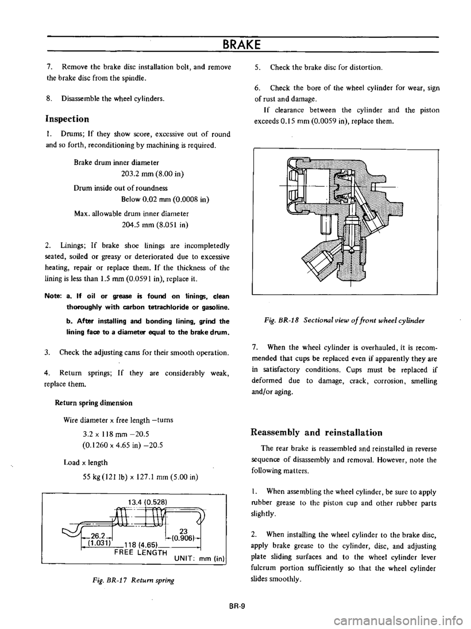
Return
spring
dimension
Wire
diameter
x
free
length
turns
3
2
x
118
mm
20
5
0
1260
x
4
65
in
20
5
Load
x
length
55
kg
I21
lb
x
127
1
mm
5
00
in
13
4
0
528
ilL
rnv
0
t
6
hl
03
118
4
65
FREE
LENGTH
UNIT
mm
in
Fig
BR
J
7
Return
spring
BRAKE
5
Check
the
brake
disc
for
distortion
6
Check
the
bore
of
the
wheel
cylinder
for
wear
sign
of
rust
and
damage
If
clearance
between
the
cylinder
and
the
piston
exceeds
0
15
mm
0
0059
in
replace
them
Fig
BR
J
8
Sectional
view
of
front
wheel
cylinder
7
When
the
wheel
cylinder
is
overhauled
it
is
recom
mended
that
cups
be
replaced
even
if
apparently
they
are
in
satisfactory
conditions
Cups
must
be
replaced
if
deformed
due
to
damage
crack
corrosion
smelling
andf
or
aging
Reassembly
and
reinstallation
The
rear
brake
is
reassembled
and
reinstalled
in
reverse
sequence
of
disassembly
and
removal
However
note
the
following
matters
When
assembling
the
wheel
cylinder
be
sure
to
apply
rubber
grease
to
the
piston
cup
and
other
rubber
parts
slightly
2
When
installing
the
wheel
cylinder
to
the
brake
disc
apply
brake
grease
to
the
cylinder
disc
and
adjusting
plate
sliding
surfaces
and
to
the
wheel
cylinder
lever
fulcrum
portion
sufficiently
so
that
the
wheel
cylinder
slides
smoothly
BR
9
Page 135 of 513

BRAKE
CYLINDER
SIDE
PISTON
SIDE
COMPR
ESSION
DECOMPRESSION
Movement
exceeding
the
elastic
displacement
is
released
with
slipping
on
the
seal
surface
Returns
in
elastic
displacement
of
the
seal
Fig
BR
21
Piston
seal
automatic
adjusting
operation
Brake
pad
Replacement
1
Jack
up
front
unit
of
the
vehicle
and
remove
lhe
front
wheeL
2
Remove
clip
from
the
retaining
pin
and
supporting
the
brake
pad
remove
the
retaining
pin
and
coil
spring
I
I
Brake
pad
2
Retaining
pin
I
31
Clip
Fig
BR
22
Removing
retaining
pin
3
Unhook
the
hanger
spring
and
withdraw
the
brake
pad
and
shim
with
a
pair
of
pliers
BR
ll
Fig
HR
2
Withdrawing
brake
pad
and
shim
Note
When
the
brake
pad
is
removed
do
not
depress
the
brake
pedal
or
otherwise
the
piston
will
come
out
Inspection
Clearance
between
the
brake
pad
and
rotor
is
adjusted
automatically
Check
the
brake
pad
for
wear
after
the
first
10
000
km
6
000
miles
driving
and
every
5
000
km
3
000
miles
thereafter
1
Clean
the
brake
pad
with
carbon
tetrachloride
or
gasoline
2
When
oil
and
or
grease
is
heavily
sticked
on
the
pad
or
when
deteriorated
or
deformed
due
to
overheating
replace
the
pad
with
a
new
one
3
When
thickness
of
the
friction
material
pad
is
less
than
1
6
mm
0
0630
in
replace
Replace
when
total
pad
thickness
is
less
than
6
1
mm
0
2402
in
Note
Replace
pads
as
a
set
Replacement
at
only
one
position
may
cause
uneven
brake
effect
It
is
recommended
that
rotation
of
pads
be
made
periodically
4
Check
the
rotor
Refer
to
Rotor
inspection
Reinstallation
1
Clean
the
calipers
and
piston
pad
installing
parts
Note
Do
not
use
mineral
oil
Be
careful
not
to
apply
oil
on
the
rotor
2
Depress
the
piston
into
the
cylinder
so
that
new
pad
can
be
installed
Page 138 of 513

CHASSIS
Note
When
cleaning
rubber
parts
use
alcohol
or
brake
fluid
If
rubber
parts
are
cleaned
with
mineral
oil
they
will
be
deteriorated
1
Calipers
If
the
cylinder
wall
is
damaged
or
worn
replace
If
the
cylinder
wall
is
rusted
or
foreign
matters
are
accumu
lated
on
the
cylinder
wall
carefully
polish
with
fine
emery
paper
so
that
the
cylinder
wall
is
not
damaged
If
rusted
or
roughened
excessively
replace
2
Pad
See
paragraph
covering
replacement
of
pad
3
Piston
Replace
if
unevenly
worn
damaged
and
or
rusted
Note
The
piston
sliding
surface
is
plated
Thus
do
not
use
emery
paper
although
rusted
or
foreign
matters
are
Slicked
on
the
sliding
surface
4
Seals
Primarily
replace
both
piston
and
dust
seals
whenever
overhauling
Note
The
piston
seal
affects
not
only
leaking
but
also
piston
return
For
this
reason
replace
the
piston
seal
even
if
the
damage
is
minor
S
Rotor
Check
the
rotor
and
if
it
shows
score
excessively
out
of
round
and
so
forth
reconditioning
by
machining
is
required
If
any
abnormal
conditions
such
as
crack
distortion
and
excessive
deflection
replace
the
rotor
Standard
rotor
thickness
9
5
mm
0
3740
in
Limit
of
reconditionillg
rotor
in
thkkn
8
4
mm
0
3307
in
Deflection
of
the
rotor
Below
0
03
mm
0
0012
in
I
I
I
I
ri
U
h
J
r
Fig
BR
1
Measuring
deflection
of
disc
Reassembly
Apply
the
rubber
grease
to
cylinder
bore
and
install
the
piston
seal
2
Insert
the
bias
ring
to
piston
A
so
that
the
roundish
portion
of
bias
ring
comes
to
the
bottom
of
piston
1
ilY
f@
I
I
C
I
1
n
tL
c
ffi
1
1
fJ
u
IZ
@
I
I
Yoke
Chamfer
13
PistonA
I
4
Roundish
portion
Fig
BR
32
Installing
bias
ring
into
piston
A
Note
Be
careful
not
to
confuse
the
piston
A
with
B
BR
14
Page 149 of 513

Pedal
yields
under
slight
pressure
Excessive
pedal
travel
All
brakes
drag
One
brake
drags
Unbalanced
brakes
BRAKE
Use
of
a
brake
fluid
with
a
boiling
point
which
is
too
low
Reservoir
filler
cap
ven
t
hole
clogged
This
promotes
a
vacuum
in
master
cylinder
that
sucks
in
air
through
rear
seal
Deteriorated
check
valve
External
leaks
Master
cylinder
leaks
through
primary
cap
System
has
not
been
bled
Improperly
adjusted
clearance
Fluid
level
in
master
cylinder
is
too
low
Thermal
expansion
of
drums
due
to
over
heating
Insufficient
shoe
tlrdrum
clearance
Weak
shoe
return
springs
Brake
shoe
return
no
free
travel
Seized
master
cylinder
piston
Loose
or
damaged
wheel
bearings
Weak
broken
or
unhooked
brake
shoe
return
springs
Insufficient
clearance
between
brake
shoe
and
drum
Grease
or
oil
on
linings
Seized
piston
in
wheel
cylinder
Tires
improperly
inflated
Loose
wheel
bearing
BR
25
Change
with
the
specified
brake
fluid
and
bleed
system
Clean
reservoir
filler
cap
and
bleed
the
system
Fit
a
new
check
valve
and
bleed
the
system
Check
master
cylinder
piping
and
wheel
cylinder
for
leaks
and
make
necessary
re
pairs
Overhaul
master
cylinder
Bleed
the
system
Adjust
shoe
to
drum
clearance
Full
up
with
specified
brake
fluid
Bleed
the
system
if
required
Allow
drums
to
cool
off
Check
brake
shoe
linings
and
drums
Replace
damaged
parts
Adjust
clearance
Replace
the
springs
Adjust
pedal
height
Service
the
master
cylinder
replace
the
piston
and
bleed
the
system
Adjust
or
replace
wheel
bearings
Replace
spring
Adjust
brakes
Clean
brake
mechanism
replace
lining
and
correct
cause
of
grease
or
oil
getting
on
lining
Service
the
wheel
cylinder
and
bleed
the
system
Inflate
tires
to
correct
pressure
Adjust
wheel
bearing
Page 150 of 513
CHASSIS
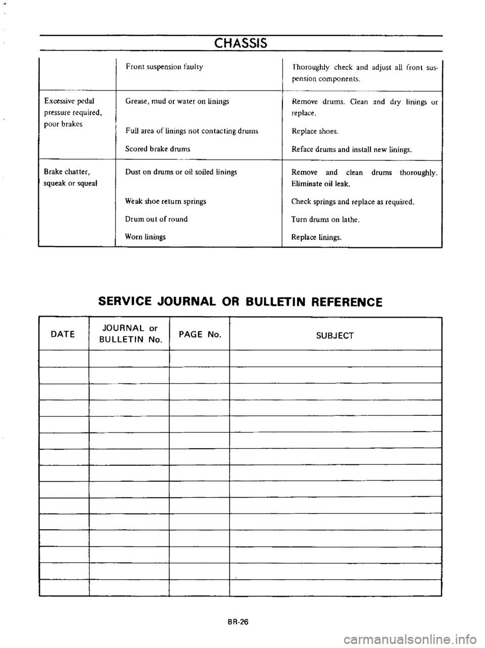
Front
suspension
faulty
Thoroughly
check
and
adjust
all
front
sus
pension
components
Excessive
pedal
pressure
required
poor
brakes
Grease
mud
or
water
on
linings
Remove
drums
Clean
and
dry
linings
or
replace
Full
area
of
linings
not
contacting
drums
Replace
shoes
Scored
brake
drums
Reface
drums
and
install
new
linings
Brake
chatter
squeak
or
squeal
Dust
on
drums
or
oil
soiled
linings
Remove
and
clean
drums
thoroughly
Eliminate
oil
leak
Weak
shoe
return
springs
Check
springs
and
replace
as
required
Drum
out
of
round
Turn
drums
on
lathe
Worn
linings
Replace
linings
SERVICE
JOURNAL
OR
BULLETIN
REFERENCE
DATE
JOURNAL
or
BULLETIN
No
PAGE
No
SUBJECT
BR
26
Page 161 of 513
STEERING
DESCRIPTION
The
steering
system
consists
of
recirculating
ball
type
gear
box
and
parallelogram
linkage
These
systems
give
good
response
light
handling
and
utmost
durability
Moreover
the
steering
linkage
is
equipped
with
a
torsion
rubber
system
idler
arm
which
absorbs
shock
from
the
wheel
Check
the
lubricant
of
gear
box
every
10
000
km
6
000
miles
and
replenish
recommended
oil
as
required
The
steering
linkage
should
be
greased
up
with
wheel
bearing
grease
every
50
000
km
30
000
miles
All
necessary
service
procedures
for
the
steering
lock
system
are
described
in
the
BODY
ELECTRICAL
SECTION
of
this
manual
and
therefore
no
instruction
is
given
here
STEERING
CONTENTS
REMOVAL
DISASSEMBL
Y
Ball
nut
assembly
ST
2
ST
3
ST
4
INSPECTION
AND
REPAIR
ASSEMBL
Y
AND
ADJUSTMENT
INSTALLATION
ST
4
ST
5
ST
7
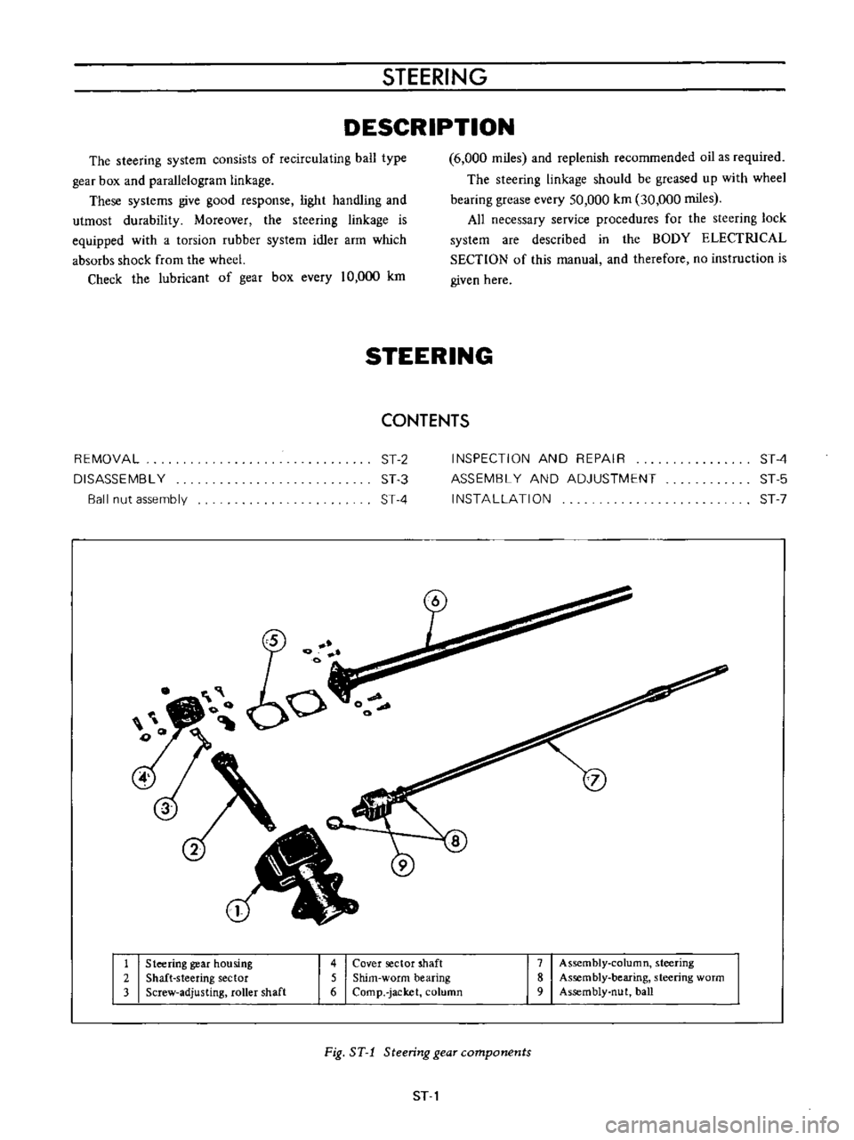
1
Steering
gear
housing
2
Shaft
steering
sector
3
Screw
adjusting
roller
shaft
4
Cover
sector
shaft
5
Shim
worm
bearing
6
Comp
jacket
column
7
Assembly
column
steering
8
Assembly
bearing
steering
worm
9
Assembly
nut
ball
Fig
ST
1
Steering
gear
components
ST
1
Page 164 of 513
CHASSIS
Note
Be
careful
not
to
allow
the
ball
nut
running
down
to
either
end
of
the
worm
The
ends
of
the
ball
guides
will
be
damaged
if
the
nut
is
allowed
to
rotate
until
stopped
at
the
end
of
the
worm
5
Pull
out
the
column
assembly
from
the
column
jacket
6
Remove
the
sector
shaft
oil
seal
7
Take
out
the
rear
bearing
outer
race
from
the
column
jacket
using
a
puller
8
Take
out
the
bearing
inner
races
from
the
front
and
rear
worm
bearings
9
Remove
the
column
shaft
bearing
Ball
nut
assembly
If
the
ball
nut
assembly
or
column
is
defective
recommend
the
column
assembly
to
be
replaced
because
assembly
and
adjustment
of
the
column
assembly
are
very
difficult
However
for
your
reference
disassembly
assembly
and
adjustment
are
described
as
follows
Disassembly
L
Remove
the
damp
of
the
ball
guide
lube
and
withdraw
the
ball
guide
tube
out
of
ball
nut
2
Turn
the
nut
upside
down
and
rotate
the
column
back
and
forth
until
all
38
balls
are
dropped
out
of
ball
nut
With
the
balls
removed
the
nul
can
be
pulled
endwise
off
the
column
Note
Be
careful
not
to
lose
the
balls
and
make
sure
that
total
number
of
balls
is
60
balls
7
32
in
dia
l
Inspection
Check
ball
guide
tubes
for
damage
at
the
ends
where
they
pick
up
the
balls
from
the
helical
path
Replace
guide
tubes
if
damaged
Assembly
and
adjustment
1
Assembie
the
ball
nut
on
the
worm
with
the
ball
guide
hole
up
2
Drop
19
balls
into
each
of
two
hoies
on
the
same
side
of
ball
nul
Turn
the
column
gradually
away
from
the
hole
being
filled
Continue
until
all
38
balls
are
installed
Note
I
n
cases
where
the
balls
are
stopped
by
the
end
of
the
column
hold
down
these
balls
already
dropped
into
the
ball
nut
with
the
blunt
end
of
a
clean
rod
or
punch
and
turn
the
column
in
the
reverse
direction
a
few
turns
The
filling
of
the
circuit
can
then
be
continued
It
may
be
o
ry
to
work
the
column
back
and
forth
holding
the
balls
down
first
in
one
hole
then
the
other
to
close
up
the
space
between
the
balls
and
fill
the
circuit
completely
and
solidly
3
Place
remammg
22
balls
in
halves
of
ball
guide
tubes
11
each
of
two
halves
4
Close
this
half
of
guide
tube
with
the
other
half
Hold
the
two
halves
together
and
plug
each
open
end
with
vaseline
so
that
balls
will
not
drop
out
while
installing
5
Push
the
guide
tubes
into
the
guide
holes
of
the
ball
nut
6
Assemble
the
ball
guide
tube
clamp
to
the
ball
nut
INSPECTION
AND
REPAIR
I
Measure
axial
clearance
between
the
steel
balls
and
ball
nut
and
if
the
clearance
is
more
than
0
08
mm
0
0031
in
replace
the
parts
as
a
complete
unit
2
Inspect
gear
teeth
of
sector
shaft
and
ball
nut
for
wear
or
damage
If
there
is
any
sign
of
damage
replace
3
Inspect
bearings
for
wear
or
chip
Replace
bearings
as
required
4
Inspect
the
serration
of
sector
shaft
and
colunm
for
wear
ST
4
Page 166 of 513
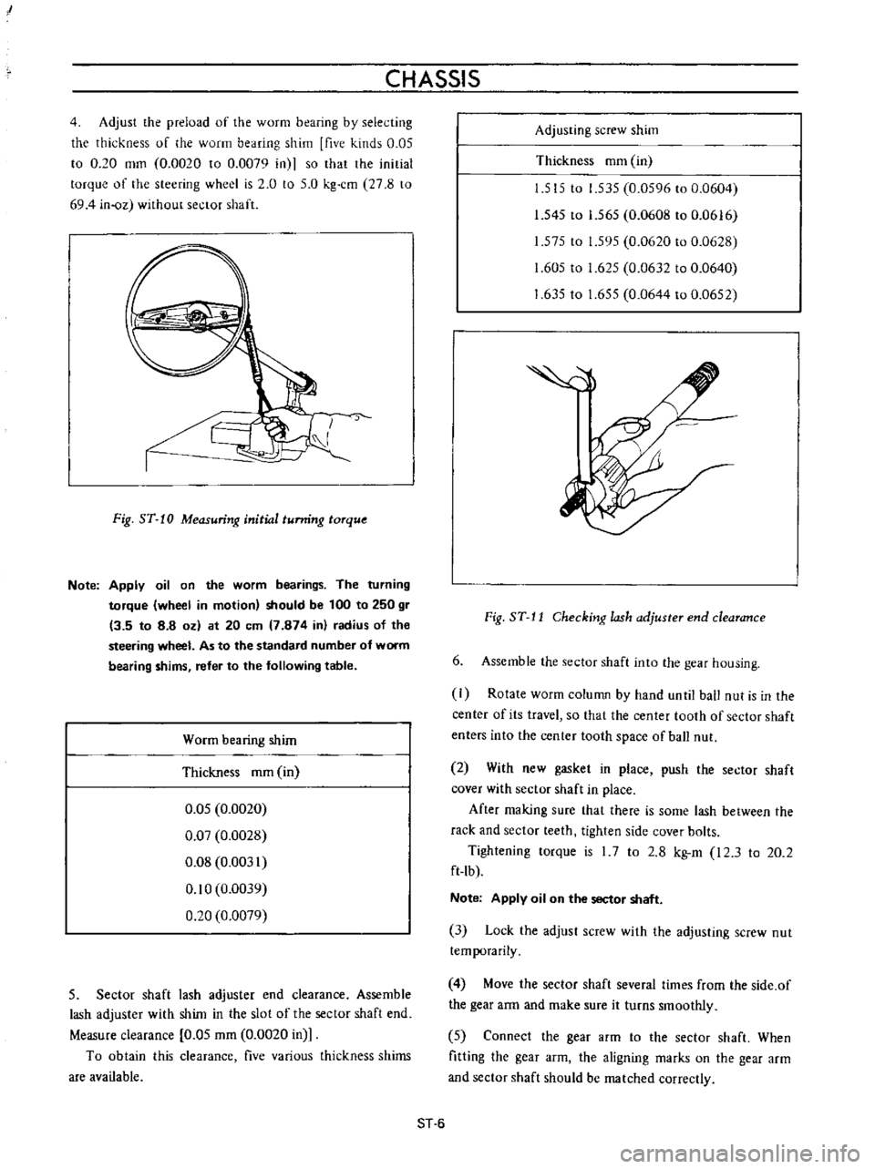
I
CHASSIS
4
Adjust
the
preload
of
the
worm
bearing
by
selecting
the
thickness
of
he
worm
bearing
shim
five
kinds
0
05
to
0
20
mm
0
0020
to
0
0079
in
so
that
the
initial
torque
of
the
steering
wheel
is
2
0
to
5
0
kg
cm
27
8
to
694
in
oz
without
sector
shaft
J
Fig
ST
10
Measuring
initial
tunring
torque
Note
Apply
oil
on
the
worm
bearings
The
turning
torque
wheel
in
motion
should
be
100
to
250
gr
13
5
to
8
8
oz
at
20
em
7
874
in
radius
of
the
steering
wheel
As
to
the
standard
number
of
worm
bearing
shims
refer
to
the
following
table
Worm
bearing
shim
Thickness
mm
in
0
05
0
0020
0
07
0
0028
0
08
0
0031
0
10
0
0039
0
20
0
0079
5
Sector
shaft
lash
adjuster
end
clearance
Assemble
lash
adjuster
with
shim
in
the
slot
of
the
sector
shaft
end
Measure
clearance
0
05
mm
0
0020
in
To
obtain
this
clearance
five
various
thickness
shims
are
available
Adjusting
screw
shim
Thickness
mm
in
1
515
to
1
535
0
0596
to
0
0604
1
545
to
1
565
0
0608
to
0
0616
1
575
to
1
595
0
0620
to
0
0628
1
605
to
1
625
0
0632
to
0
0640
1
63510
1
655
0
0644
to
0
0652
Fig
ST
J
J
Checking
lash
adjuster
end
clearance
6
Assemble
the
sector
shaft
into
the
gear
housing
I
Rotate
worm
column
by
hand
unlil
ball
nut
is
in
the
center
of
its
travel
so
that
the
center
tooth
of
sector
shaft
enters
into
the
center
tooth
space
of
ball
nut
2
With
new
gasket
in
place
push
the
sector
shaft
cover
with
sector
shaft
in
place
After
making
sure
that
there
is
some
lash
between
the
rack
and
sector
teeth
tighten
side
cover
bolts
Tightening
torque
is
I
7
to
2
8
kg
m
I2
3
to
20
2
ft
lb
Note
Apply
oil
on
the
sector
shaft
3
Lock
the
adjust
screw
with
the
adjusting
screw
nut
temporarily
4
Move
the
sector
shaft
several
times
from
the
side
of
the
gear
arm
and
make
sure
it
turns
smoothly
5
Connect
the
gear
arm
to
the
sector
shaft
When
fitting
the
gear
arm
the
aligning
marks
on
the
gear
arm
and
sector
shaft
should
be
matched
correctly
ST
6