Page 339 of 513
ENGINE
Improper
air
fueled
mixtur
into
cylinder
walls
Check
the
fuel
system
Seizure
of
sliding
parts
Lkl
rease
of
oil
pressure
Previously
mentioned
Insufficient
clearances
Reassemble
with
the
designated
clear
ances
Overheat
Previously
mentioned
Improper
fuel
mixture
Check
the
fuel
system
SERViCE
JOURNAL
OR
6UU
ETIi
l
REFERENCE
DATE
JOURNAL
or
BULLETIN
No
PAGE
No
SUBJECT
ET
34
1t
Page 344 of 513
ENGINE
Fig
EM
IO
Intake
manifold
Fig
EM
12
Intake
and
exhaust
manifolds
Fig
EM
It
Exhaust
manifold
ENGINE
DISASSEMBLY
CONTENTS
CLEANING
AND
INSPECTION
DISASSEMBL
Y
EM
4
EM
5
PISTON
AND
CONNECTING
ROD
CYLINDER
HEAD
EM
7
EM
7
CLEANING
AND
INSPECTION
breakage
rust
damage
and
loss
Clean
the
engine
thoroughly
before
disassembly
Before
cleaning
the
engine
remove
the
electrical
parts
and
plug
up
the
carburetor
air
horn
to
avoid
intrusio
n
of
foreign
matter
2
Cylinder
block
Check
thoroughly
the
water
jacket
for
cracks
and
breakage
3
Clutch
howing
Check
for
cracks
1
The
engine
exterior
Check
the
covers
and
bolts
for
4
Oil
pan
Check
for
excessive
rust
EM
4
Page 348 of 513
ENGINE
J
I
r
I
I
J
fj
7
L
j
8
if
d1
I
ilfi
3
c
7
I
t
j
v
1
Ji
Fig
EM
27
Valve
mo
1
2
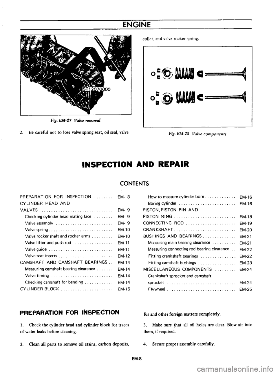
Be
careful
not
to
lose
valve
spring
seat
oil
seal
valve
collet
and
valve
rocker
spring
O
tj
AAAftIl
C
e
WWII
o
glAWle
Fig
EM
28
Valve
components
INSPECTION
AND
REPAIR
CONTENTS
PREPARATION
FOR
INSPECTION
EM
8
How
to
measure
cylinder
bore
EM
16
CYLlNOER
HEAD
AND
80ring
cylinder
EM
16
VALVES
EM
9
PISTON
PISTON
PIN
AND
Checking
cylinder
head
mating
face
EM
9
PISTON
RING
EM
18
Valve
assembly
EM
9
CONNECTING
ROD
EM
19
Valve
spring
EM
10
CRANKSHAFT
EM
20
Valve
rocker
shaft
and
rockei
arms
EM
lO
BUSHINGS
AND
BEARINGS
EM
21
Valve
lifter
and
push
rud
EM
11
Measuring
main
bearing
clearance
EM
21
Valve
guide
EM
11
Measuring
connecting
rod
bearing
clearance
EM
22
Valve
seat
inserts
EM
12
Fitting
crankshaft
bearings
EM
22
CAMSHAFT
AND
CAMSHAFT
BEARINGS
EM
14
Fitting
camshaft
bushings
EM
23
Measuring
camshaft
bearing
clearance
EM
14
MISCELLANEOUS
COMPONENTS
EM
24
Valve
timing
EM
14
Crankshaft
sprocket
and
camshaft
Checking
camshaft
for
bending
EM
14
sprocket
EM
24
CYLlNOER
BLOCK
EM
15
Flywheel
EM
25
PREPARATION
FOR
INSPECTION
L
Check
the
cylinder
head
and
cylinder
block
for
traces
of
water
leaks
before
cleaning
2
Clean
all
parts
to
remove
oil
stains
carbon
deposits
fur
and
other
foreign
matters
completely
3
Make
sure
that
all
oil
holes
are
clear
Blow
air
into
them
if
required
4
Secure
proper
assembly
carefully
EM
8
Page 350 of 513
ENGINE
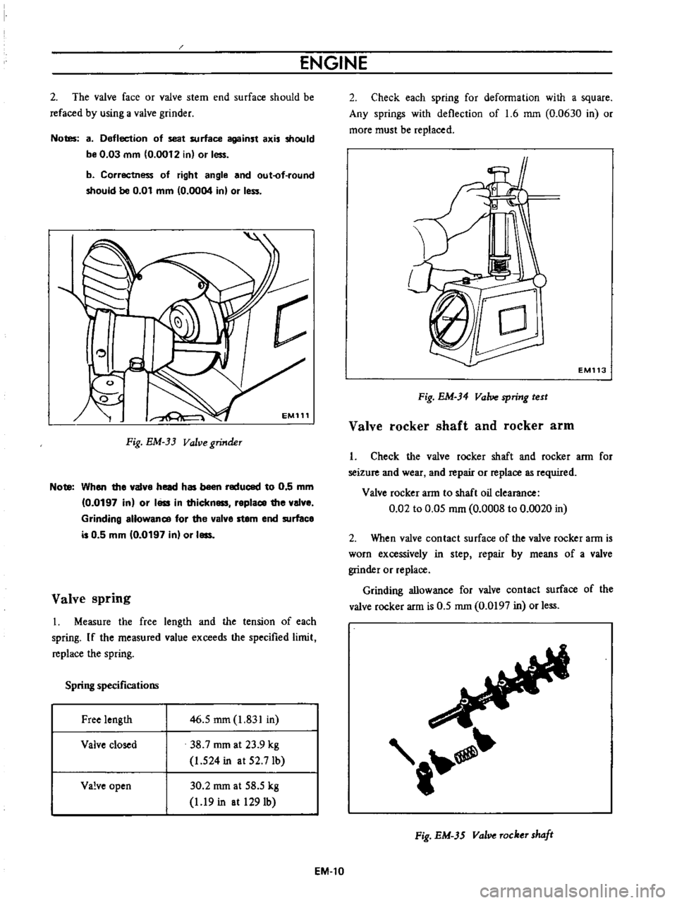
2
The
valve
face
or
valve
stem
end
surface
should
be
refaced
by
using
a
valve
grinder
Notes
a
Deflection
of
seat
surface
against
axis
should
be
0
03
mm
0
0012
in
or
less
b
Correctness
of
right
angle
and
out
of
round
should
be
0
01
mm
0
0004
in
or
I
c
EM111
Fig
EM
33
Valve
grinder
Note
When
the
a1ve
head
has
been
reduced
to
0
5
mm
0
0197
in
or
I
in
thickn
replace
the
al
e
Grinding
allowance
for
the
alve
stem
end
surface
is
0
5
mm
10
0197
in
or
I
Valve
spring
I
Measure
the
free
length
and
the
tension
of
each
spring
If
the
measured
value
exceeds
the
specified
limit
replace
the
spring
Spring
specifications
Free
length
46
5
mm
1
831
in
38
7
rom
at
23
9
kg
1
524
in
at
52
7Ib
Valve
closed
Valve
open
30
2
rom
at
58
5
kg
1
19
in
at
1291b
EM
l0
2
Check
each
spring
for
deformation
with
a
square
Any
springs
with
deflection
of
1
6
mm
0
0630
in
or
more
must
be
replaced
EM113
Fig
EM
34
Valve
spring
test
Valve
rocker
shaft
and
rocker
arm
I
Check
the
valve
rocker
shaft
and
rocker
arm
for
seizure
and
wear
and
repair
or
replace
as
required
Valve
rocker
arm
to
shaft
oil
clearance
0
02
to
0
05
mm
0
0008
to
0
0020
in
2
When
valve
contact
surface
of
the
valve
rocker
arm
is
worn
excessively
in
step
repair
by
means
of
a
valve
grinder
or
replace
Grinding
allowance
for
valve
contact
surface
of
the
valve
rocker
arm
is
0
5
rom
0
0197
in
or
less
t
Fig
EM
3S
val
Tocker
shaft
Page 354 of 513
ENGINE
CAMSHAFT
AND
CAMSHAFT
BEARING
Measuring
camshaft
bearing
clearance
Measure
inner
diameter
of
the
camshaft
bearing
and
outer
diameter
of
the
camshaft
journaL
If
camshaft
bearing
clearance
is
excessive
replace
the
cylinder
block
assembly
Limit
0
15mm
0
0059
in
Standard
o
oi
to
0
07mm
M012
to
0
0627
in
Fig
EM
42
Camshaft
bearing
check
1st
2nd
Oil
clearance
mm
in
3rd
4th
5th
1st
Inner
I
2nd
I
diameter
of
I
I
camshaft
3rd
bearing
mm
in
14th
I
15th
I
Standard
0
037
to
0
060
0
0015
to
0
0024
0
027
to
0
050
0
00
to
0
0020
0
040
to
0
063
0
0016
to
0
0025
0
027
to
0
050
0
0011
to
0
0020
0
037
to
0
060
0
0015
to
0
0024
43
833
to
43
843
i
7257
to
I
7261
43
323
to
43
333
l
7050
to
1
7060
42
836
to
42
846
1
6865
to
1
6868
42
323
to
42
333
1
6663
to
1
6667
41
258
to
41
268
1
6243
to
1
6247
Wear
limit
0
15
0
0059
1
1
1
1
Valve
timing
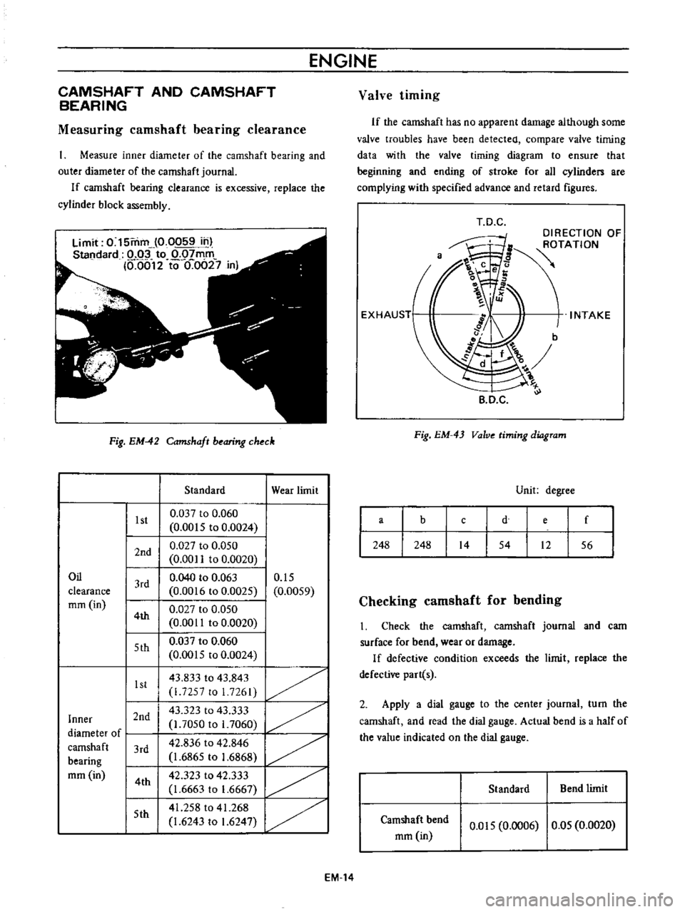
If
the
camshaft
has
no
apparent
damage
although
some
valve
troubles
have
been
detected
compare
valve
timing
data
with
the
valve
timing
diagram
to
ensure
that
beginning
and
ending
of
stroke
for
all
cylinden
are
complying
with
specified
advance
and
retard
figures
T
D
C
DIRECTION
OF
ROTATION
INTAKE
B
D
C
Fig
EM
43
Valve
timing
diagram
Unit
degree
a
b
e
f
d
c
248
248
14
54
12
56
Checking
camshaft
for
bending
Check
the
camshaft
camshaft
journal
and
cam
surface
for
bend
wear
or
damage
If
defective
condition
exceeds
the
limit
replace
the
defective
part
s
2
Apply
a
dial
gauge
to
the
center
journal
turn
the
camshaft
and
read
the
dial
gauge
Actual
bend
is
a
half
of
the
value
indicated
on
the
dial
gauge
Standard
Bend
limit
Camshaft
bend
mm
in
0
015
0
0006
0
05
0
0020
EM
14
Page 358 of 513
ENGINE
PISTON
PISTON
PIN
AND
PISTON
RING
Check
for
seizure
scratch
and
wear
Replace
as
required
o
10
e
O
I
l
Fig
EM
51
Piston
and
connecting
rod
assembly
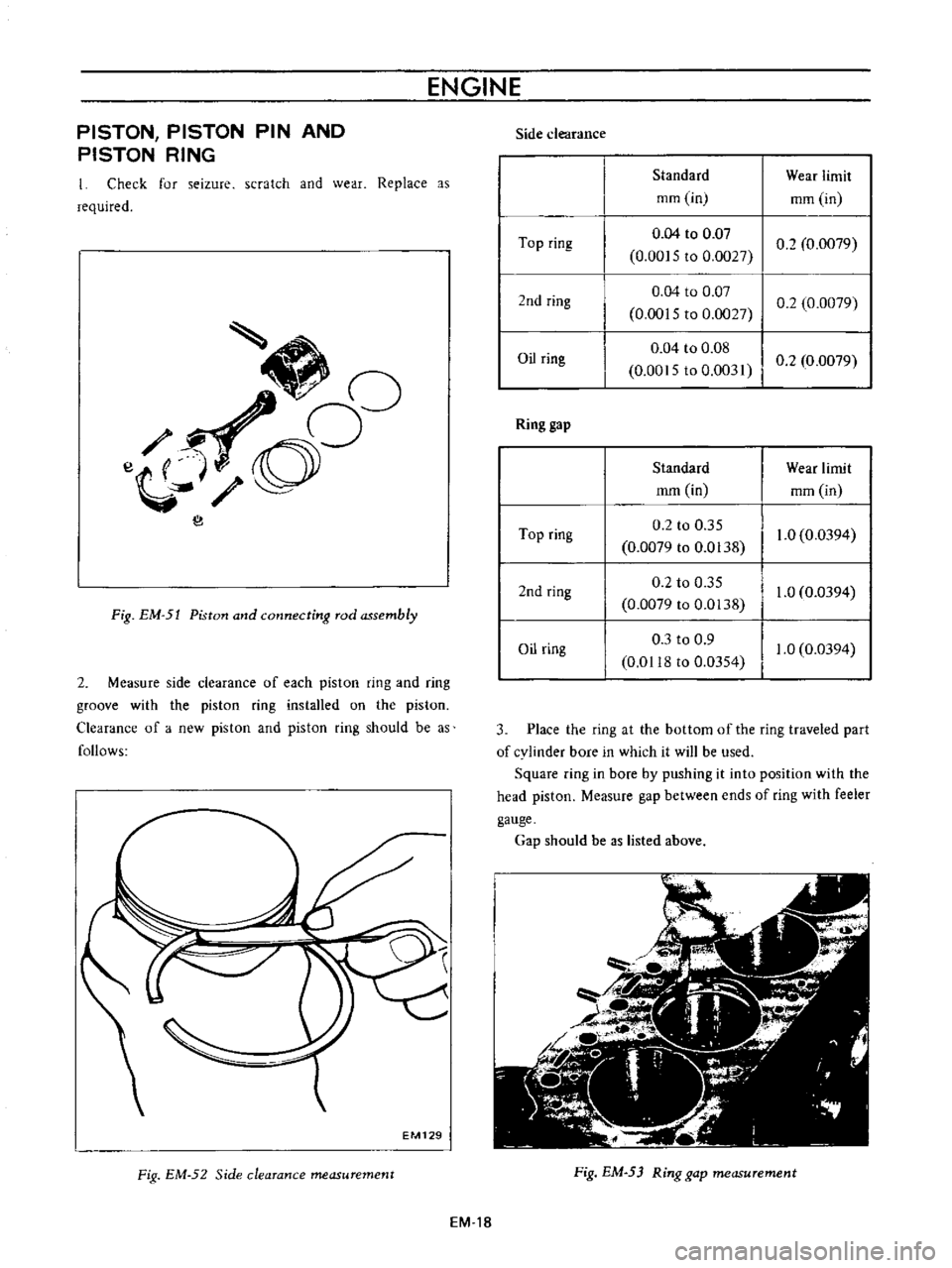
2
Measure
side
clearance
of
each
piston
ring
and
ring
groove
with
the
piston
ring
installed
on
the
piston
Clearance
of
a
new
piston
and
piston
ring
should
be
as
follows
EM129
Fig
EM
52
Side
clearance
measurement
EM
18
Side
clearance
Standard
Wear
limit
mm
in
mm
in
Top
ring
0
04
to
0
Q7
02
0
0079
0
00
5
to
0
0027
2nd
ring
0
04
to
0
07
0
0015
to
0
027
0
2
0
0079
Oil
ring
0
04
to
0
08
0
0015
to
0
0031
I
0
2
0
0079
Ring
gap
Standard
Wear
limit
mm
in
mm
in
Top
ring
0
2
to
0
35
1
0
0
0394
0
0079
to
0
0138
2nd
ring
0
2
to
0
35
1
0
0
0394
0
0079
to
0
0138
Oil
ring
0
3
to
0
9
1
0
0
0394
0
01
8
to
0
0354
3
Place
the
ring
at
the
bottom
of
the
ring
traveled
part
of
cylinder
bore
in
which
it
will
be
used
Square
ring
in
bore
by
pushing
it
into
position
with
the
head
piston
Measure
gap
between
ends
of
ring
with
feeler
gauge
Gap
should
be
as
listed
above
Fig
EM
53
Ring
gap
measurement
Page 361 of 513
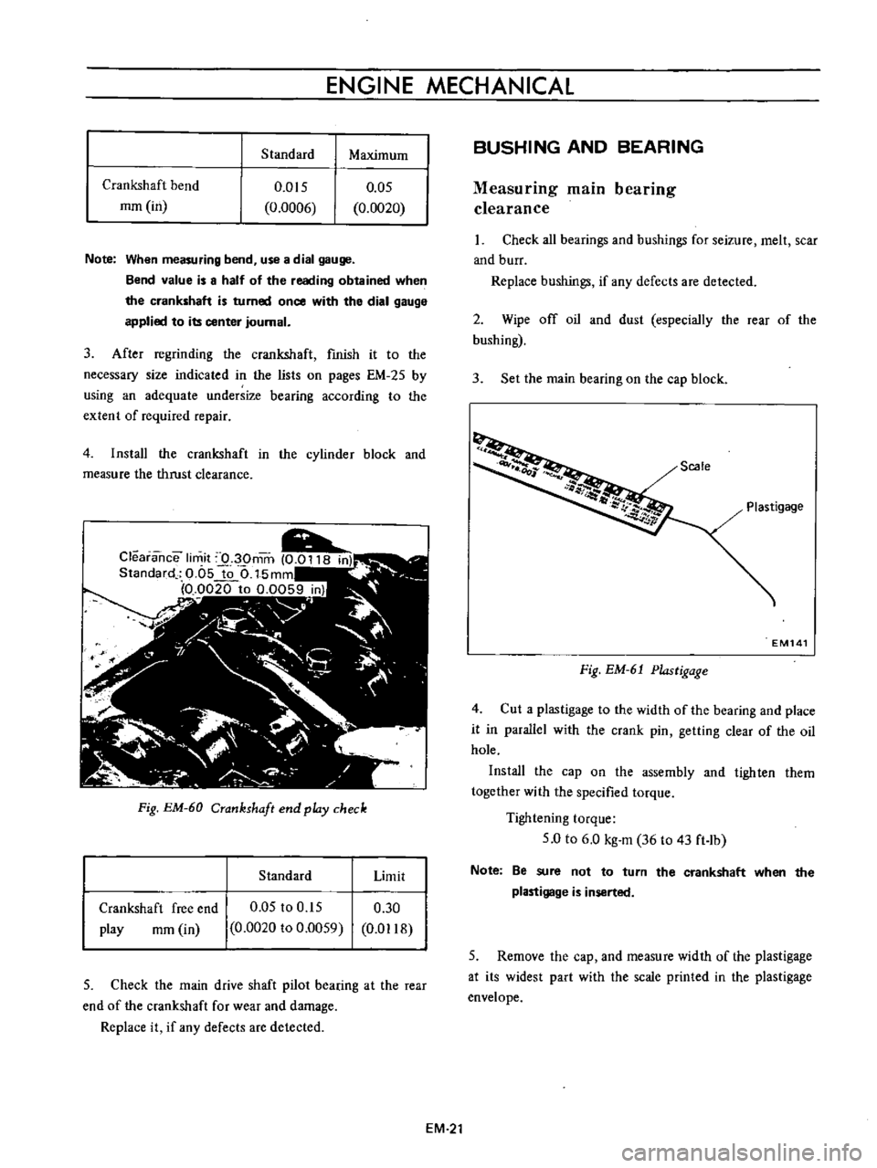
ENGINE
MECHANICAL
Standard
Maximum
Crankshaft
bend
mm
in
0
05
0
0020
0
015
0
0006
Note
When
measuring
bend
use
a
dial
gauge
Bend
value
is
a
half
of
the
reading
obtained
when
the
crankshaft
is
turned
once
with
the
dial
gauge
applied
to
its
center
journal
3
After
regrinding
the
crankshaft
fmish
it
to
the
necessary
size
indicated
in
the
lists
on
pages
EM
25
by
using
an
adequate
undersize
bearing
according
to
the
extent
of
required
repair
4
Install
the
crankshaft
in
the
cylinder
block
and
measure
the
thrust
clearance
Fig
EM
60
Crankshaft
end
pldy
check
Standard
Limit
Crankshaft
free
end
play
rom
in
0
05
to
0
15
0
0020
to
0
0059
0
30
0
D118
5
Check
the
main
drive
shaft
pilot
bearing
at
the
rear
end
of
the
crankshaft
for
wear
and
damage
Replace
it
if
any
defects
are
detected
BUSHING
AND
BEARING
Measuring
main
bearing
clearance
Check
all
bearings
and
bushings
for
seizure
melt
scar
and
burr
Replace
bushings
if
any
defects
are
detected
2
Wipe
off
oil
and
dust
especially
the
rear
of
the
bushing
3
Set
the
main
bearing
on
the
cap
block
Scale
Plastigage
EM141
Fig
EM
61
Plastigage
4
Cut
a
plastigage
to
the
width
of
the
bearing
and
place
it
in
parallel
with
the
crank
pin
getting
clear
of
the
oil
hole
Install
the
cap
on
the
assembly
and
tighten
them
together
with
the
specified
torque
Tightening
torque
5
0
to
6
0
kg
m
36
to
43
ft
lb
Note
Be
sure
not
to
turn
the
crankshaft
when
the
plastigage
is
inserted
5
Remove
the
cap
and
measure
width
of
the
plastigage
at
its
widest
part
with
the
scale
printed
in
the
plastigage
envelope
EM
21
Page 362 of 513
ENGINE
Pig
EM
62
Bearing
clearance
check
Measuring
connecting
rod
bearing
clearance
Measure
connecting
rod
bearing
clearance
in
the
same
manner
Tightening
torque
3
2
to
3
8
kg
m
23
to
28
ft
Ib
Bearing
oil
clearance
Standard
Wear
limit
Main
bearing
clearance
rom
in
0
020
to
0
062
0
0008
to
0
0024
0
1
0
0039
Connecting
rod
bearing
clearance
mm
in
0
020
to
0
050
0
0008
to
0
0020
0
1
0
0039
2
If
clearance
exceeds
the
specified
value
replace
bearing
with
an
undersize
bearing
and
grind
out
the
crankshaft
journal
adequately
Fig
EM
63
Bearing
clearance
check
Fitting
crankshaft
bearings
I
Set
the
bushings
on
the
main
bearing
cap
and
the
cylinder
block
bearing
recess
and
tighten
the
cap
bolts
to
the
specified
torque
Tightening
torque
5
0
to
5
3
kg
m
36
to
38
ft
lb
2
Loosen
the
cap
bolt
on
one
side
and
measure
clearance
between
the
cap
and
cylinder
block
side
n
n
u
ii
Bearing
6
Weight
EM143
Fig
EM
64
Bearing
crush
check
EM
22