1973 DATSUN B110 roof
[x] Cancel search: roofPage 41 of 513

AUTOMATIC
TRANSMISSIO
N
i
MAJOR
REPAIR
OPERATION
SERVICE
NOTICE
FOR
DISASSEMBLY
AND
ASSEMBLY
TORQUE
CONVERTER
Inspection
TRANSMISSION
Disassembly
Inspection
Assembly
SERVICE
NOTICE
FOR
DISASSEMBLY
AND
ASSEMBLY
I
It
is
desirable
that
the
repair
operations
are
carried
out
in
the
dust
proof
room
2
Due
to
the
differences
of
the
engine
capacities
the
specifications
of
component
parts
for
each
model
s
transmission
may
be
different
How
ever
they
do
have
common
adJust
ments
and
repair
as
well
as
cleaning
and
inspection
procedures
ou
tlined
hereinafter
3
During
the
repair
operations
refer
to
the
Service
Data
and
Specifi
cations
section
for
the
correct
parts
for
the
applicable
model
transmission
4
Before
removing
any
of
subas
semblies
thoroughly
clean
the
outside
of
the
transmission
to
preven
t
dirt
from
entering
the
mechanical
parts
5
Do
not
use
a
waste
rag
Use
a
nylon
waste
or
paper
waste
6
After
disassembling
wash
all
dis
assembled
parts
clean
and
examine
them
to
see
if
there
are
any
worn
damaged
or
defective
parts
and
how
they
are
affected
Refer
to
Service
Data
for
the
extent
of
damage
that
justifies
replacement
7
Packings
seals
and
similar
parts
once
disassembled
should
be
replaced
with
new
ones
as
a
rule
TORQUE
CONVERTER
CONTENTS
AT
37
AT
37
AT
37
AT
37
AT
37
AT
39
AT
39
COMPONENT
PARTS
F
rant
clutch
Rear
clutch
Low
reverse
brake
Servo
piston
Governor
Oil
pump
Planetary
carrier
Control
valve
The
torque
converter
is
a
welded
construction
and
can
not
be
disas
sembled
Inspection
I
Check
torque
converter
for
any
sign
of
damage
bending
oil
leak
or
deformation
If
necessary
replace
2
Remove
rust
from
pilots
and
bosses
completely
If
torque
converter
oil
is
fouled
or
contaminated
due
to
burnt
clutch
flush
the
torque
converter
as
follows
I
Drain
oil
in
torque
converter
2
Pour
none
Iead
gasoline
or
kero
sene
into
torque
converter
approxi
mately
0
5
liter
I
1
8
V
S
p
7
8
Imper
p
3
Blow
air
into
torque
converter
and
flush
and
drain
out
gasoline
4
Fill
torque
converter
oil
into
torque
converter
approximately
0
5
liter
I
i
8
I
pt
7
8
lmper
pt
5
Again
blow
air
into
torque
con
verter
and
drain
torque
converter
oil
TRANSMISSION
Disassembly
I
Drain
oil
from
the
end
of
rear
extension
Mount
transmission
on
Transmission
Case
Stand
ST07860000
or
ST07870000
Remove
oil
pan
See
Figure
AT
52
AT
37
T
AT
41
AT
41
AT
42
AT
43
AT
43
AT
44
AT
44
AT
45
AT
45
2
Remove
bolts
securing
converter
housing
to
transmission
case
Remove
torque
converter
3
Remove
speedometer
pinion
sleeve
boll
Withdraw
pinion
4
Turn
off
by
hand
downshift
sole
noid
and
vacuum
diaphragm
Do
not
leave
diaphragm
rod
at
this
stage
of
disassembly
Rod
is
assembled
in
top
of
vacuum
diaphragm
See
Figure
AT
53
ST07860000
AT118
Fig
AT
52
Remouing
oil
pan
Show
2
liter
engine
model
Fig
A
T
53
Downshift
solenoid
and
uacuum
diaphragm
Page 54 of 513

through
all
drive
positions
and
place
the
lever
in
park
P
position
In
this
inspection
the
car
must
be
placed
on
a
level
surface
The
amount
of
the
oil
varies
with
the
temperature
As
a
rule
the
oil
level
must
be
measured
after
its
tempera
ture
becomes
sufficiently
high
I
Fill
the
oil
to
the
line
H
The
difference
of
capacities
between
both
H
and
L
is
approximately
0
4
liter
7
8
U
S
pt
3
4
Imper
pt
and
therefore
take
care
not
to
fill
beyond
the
line
H
2
At
the
time
of
the
above
topping
up
and
changing
of
oil
care
should
be
taken
of
to
prevent
mixing
the
oil
with
dust
and
water
2
Inspecting
oil
condition
The
condition
of
oil
sticking
to
the
level
gauge
indicates
whether
to
over
haul
and
repair
the
transmission
or
look
for
the
defective
part
If
the
oil
has
deteriorated
into
a
varnish
like
quality
it
causes
the
con
trol
valve
to
stick
The
blackened
oil
gives
the
proof
of
the
burned
clutch
brake
band
etc
In
these
cases
the
transmission
must
be
replaced
Notes
a
In
oil
level
checking
use
special
paper
waste
to
handle
the
level
gauge
and
take
care
not
to
let
the
scraps
of
paper
and
cloth
tick
to
the
gauge
b
Insert
the
gauge
fully
and
take
it
out
quickly
before
splashing
oil
adheres
to
the
gauge
and
theu
observe
the
level
c
Use
automatic
transmission
fluid
having
DEXRON
iden
tIficatIon
only
in
the
3N71
B
automatic
transmission
d
Pay
atteutIon
because
the
oil
to
be
used
dIffers
from
that
i
used
in
the
Nissan
Full
Automatic
Transmission
3N7IA
Never
mix
the
oil
with
that
CHASSIS
Inspection
and
repair
of
oil
leakage
When
oil
leakage
takes
place
the
portion
near
the
leakage
is
covered
with
oil
presenting
difficulty
in
de
tecting
the
spot
Therefore
the
places
where
oil
seals
and
gaskets
are
equipped
are
enumerated
below
I
Converter
housing
The
rubber
ring
of
oil
pump
hous
ing
The
oil
eaI
of
oil
pump
housing
The
oil
seal
of
engine
crankshaft
The
bolts
of
converter
housing
to
case
2
Transmission
and
rear
extension
Junction
of
transmission
and
rear
extension
Oil
tube
connectors
Oil
pan
Oil
pressure
inspection
holes
Refer
to
Figure
AT
112
The
mounting
portion
of
vacuum
diaphragm
and
downshift
solenoid
Breather
and
oil
charging
pipe
Speedometer
pinion
sleeve
The
oil
seal
of
rear
extension
To
exactly
locate
the
place
of
oil
leakage
proceeds
as
follows
Place
the
vehicle
in
a
pit
and
by
sampling
the
leaked
oil
examine
whe
ther
it
is
the
torq
le
converter
oil
or
not
The
torque
converter
oil
assumes
color
like
red
wine
when
shipped
from
the
factory
so
it
is
ea
ily
distin
guished
from
engine
oil
or
gear
oil
Cleanly
wipe
off
the
leaking
oil
and
dust
and
detect
the
spot
of
oil
leakage
Use
nonflammable
organic
solvent
such
as
carbon
tetrachloride
for
wip
ing
Raise
the
oil
temperature
by
op
erating
the
engine
and
shift
the
lever
to
0
to
heighten
the
oil
pressure
The
spot
of
oil
leakage
will
then
be
found
more
easily
Note
A
the
oil
leakage
from
the
breather
does
not
take
place
except
when
running
at
high
speed
it
is
impossible
to
locate
the
spot
of
leakage
with
vehicle
stalled
AT
50
Checking
engine
idling
rprn
The
engine
idling
revolution
should
be
properly
adjusted
If
the
engine
revolution
is
too
low
the
engine
does
not
operate
smoothly
and
if
too
high
a
strong
shock
or
creep
develops
when
changing
over
from
N
to
D
or
R
Specified
idling
speed
650
rpm
at
D
position
800
rpm
at
N
position
Checking
and
adjusting
kick
down
switch
and
downshift
solenoid
When
the
kick
down
operation
is
not
made
properly
or
the
speed
chang
ing
point
is
too
high
check
the
kick
down
switch
downshift
solenoid
and
wiring
between
them
When
the
igni
tion
key
is
positioned
at
the
1st
stage
and
the
accelerator
pedal
is
depressed
deeply
the
switch
contact
should
be
closed
and
the
solenoid
should
click
If
it
does
not
click
it
indicates
a
defect
Then
check
each
part
with
the
testing
instruments
See
Figure
AT
I09
0
0
1
M
r
7
I
Y
ATl08
Fig
A
T
l
09
Downshift
solenoid
Note
Watch
for
oil
leakage
from
transmission
case
Page 95 of 513
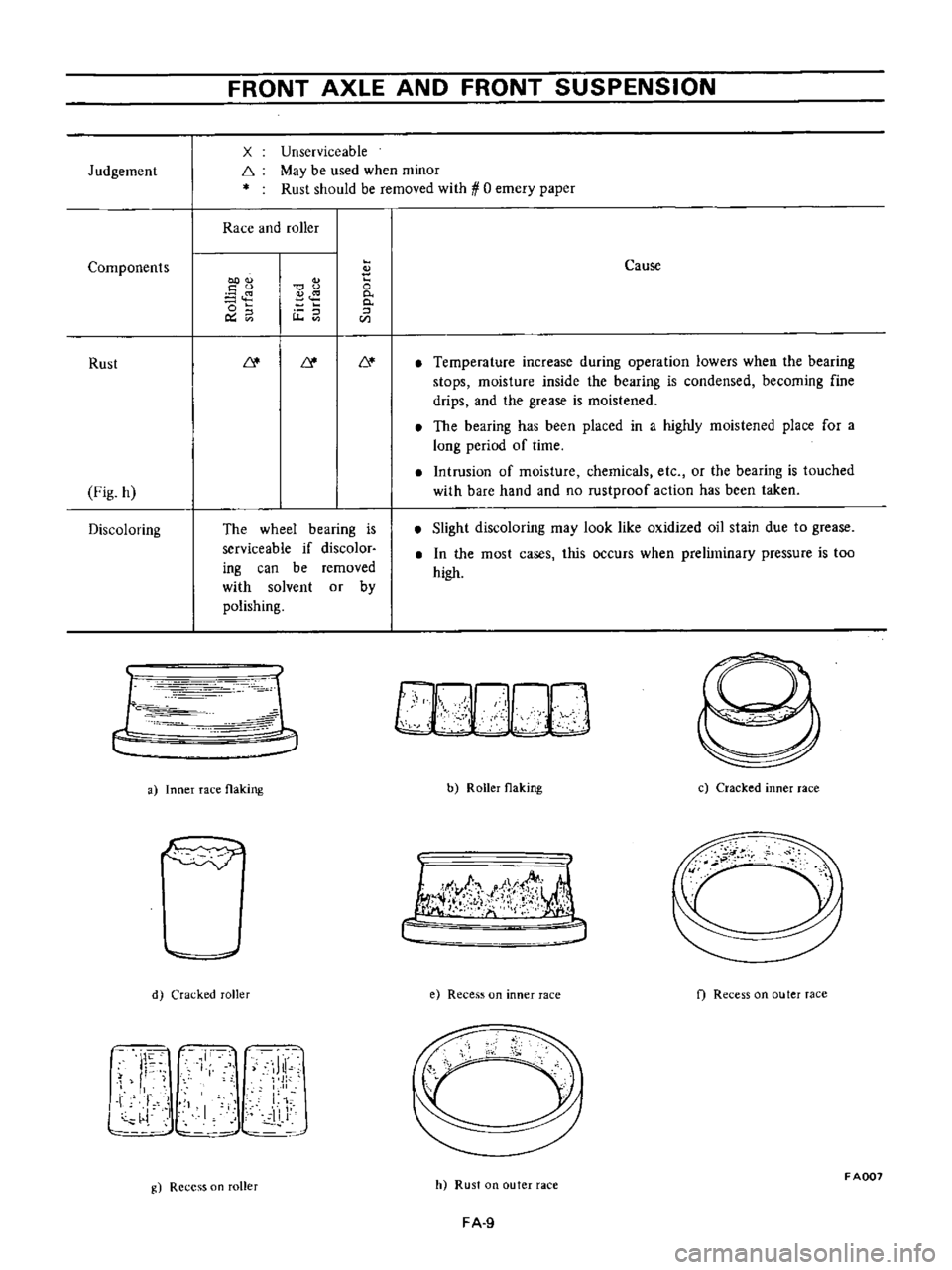
Judgement
Components
Rust
Fig
h
Discoloring
FRONT
AXLE
AND
FRONT
SUSPENSION
x
f
Unserviceable
May
be
used
when
minor
Rust
should
be
removed
with
0
emery
paper
Race
and
roller
00
u
o
o
Ou
u
The
wheel
bearing
is
serviceable
if
discolor
ing
can
be
removed
with
solvent
or
by
polishing
r
c
1
1
Ie
r
r
iJ
a
Inner
race
flaking
d
Cracked
roller
J
I
11
Ji
l
L
i
I
11
J
g
Recess
on
roller
o
0
0
CIl
Cause
Temperature
increase
during
operation
lowers
when
the
bearing
stops
moisture
inside
the
bearing
is
condensed
becoming
fine
drips
and
the
grease
is
moistened
The
bearing
has
been
placed
in
a
highly
moistened
place
for
a
long
period
of
time
Intrusion
of
moisture
chemicals
etc
or
the
bearing
is
touched
with
bare
hand
and
no
rustproof
action
has
been
taken
Slight
discoloring
may
look
like
oxidized
oil
stain
due
to
grease
In
the
most
cases
this
occurs
when
preliminary
pressure
is
too
high
b
Roller
flaking
c
Cracked
inner
race
I
lJ
f
t
j
e
Recess
on
inner
race
f
Recess
on
outer
race
cc
h
Rust
on
outer
race
FADD7
FA
9
Page 193 of 513
@
7
11
@
C
C
B
B
@
I
L
IJ
A
A
F
F
n
18
@
1
@
H
H
@
@
Y
J
@
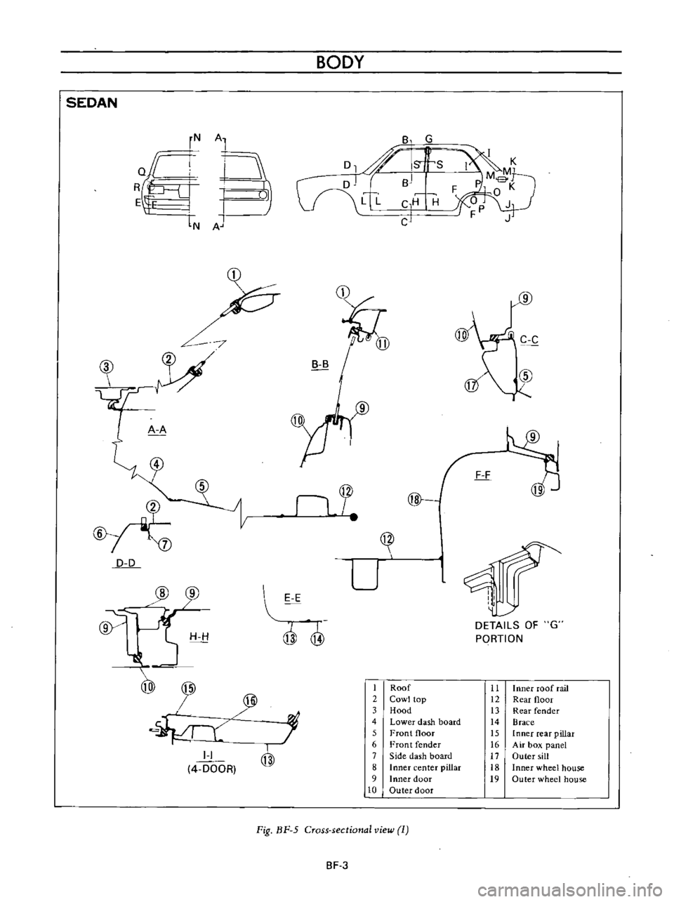
SEDAN
rN
Al
RQ
I
l
E
IN
A
D
D
I
I
4
DOOR
BODY
8
G
D1
J
Is
s
r
Jn
BJ
V
V
L
C
H
H
CJ
U
I
II
I
E
E
Q
@
DETAILS
OF
G
PORTION
1
Roof
11
Inner
roof
rail
2
Cowl
top
12
Rear
floor
3
Hood
13
Rear
fender
4
Lower
dash
board
14
Brace
5
Front
floor
15
Inner
reaT
pillar
6
Front
fender
16
Air
box
panel
7
Side
dash
board
17
Outer
sill
B
Inner
center
pillar
18
Inner
wheel
house
9
Inner
dOOf
19
Outer
wheel
house
10
Outer
door
Fig
nF
5
Cross
sectional
view
1
BF
3
Page 194 of 513
J
J
CD
11
BODY
I
K
L
L
N
N
@
r
T
I
c
cb
I
cp
M
M
J
Ii
0
0
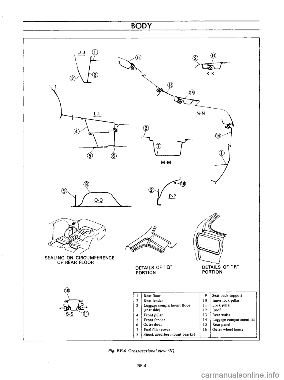
SEALING
ON
CIRCUMFERENCE
OF
REAR
FLOOR
@
Ii
DETAILS
OF
Q
PORTION
DETAILS
OF
R
PORTION
1
Rear
floor
2
Rear
fender
3
Luggage
compartment
floor
rear
side
4
Front
pillar
5
Front
fender
6
Ou
tee
door
7
Fue
filler
cover
8
Shock
absorber
mount
bracket
9
Seat
back
support
10
Inner
lock
pillar
11
Lock
pillar
12
Roof
13
Rear
waist
14
Luggage
compartment
lid
15
Rear
panel
16
Outer
wheel
house
Fig
BF
6
Cross
sectional
view
II
BF
4
Page 195 of 513
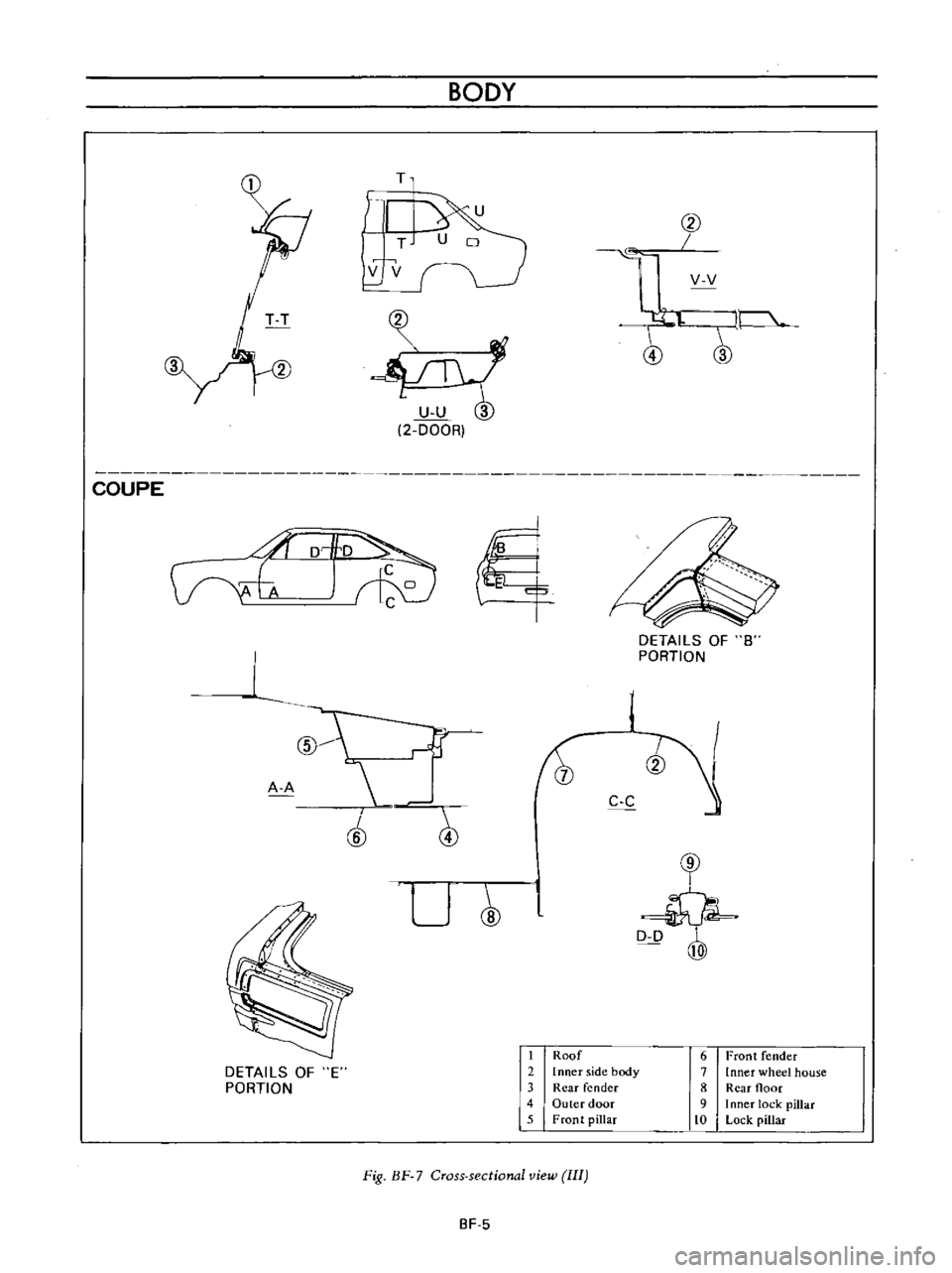
COUPE
BODY
T
@
T
v
v
vv
l
2
DOOR
1
5
Vv
t
t
tJ
DETAILS
OF
8
PORTION
1
r
I
A
A
J
C
C
j
@
cr
U
D
D
@
DETAILS
OF
E
PORTION
1
Roof
2
Inner
side
body
3
Rear
fender
4
Outer
door
5
Front
pillar
6
Front
fender
7
loner
wheel
house
8
Rear
floor
9
I
Rner
lock
pilla
c
to
Lock
pillar
Fig
BF
7
Cross
sectional
view
III
SF
5
Page 196 of 513
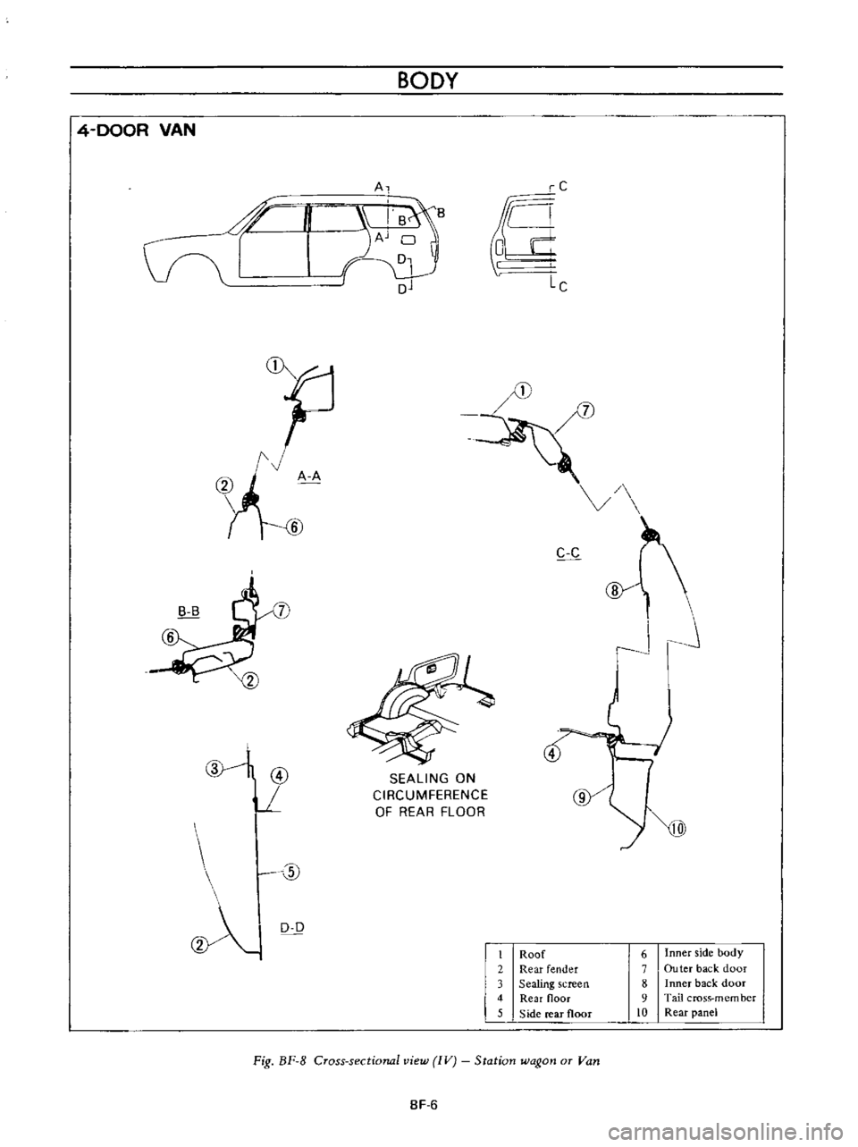
BODY
4
DOOR
VAN
A
i
d
n
S
Cr
Aj
c
oj
Lc
f
w
C
c
J
@
L
4
SEALING
ON
CIRCUMFERENCE
OF
REAR
FLOOR
w
@
0
0
0
Roof
6
Inner
side
body
Rear
fender
7
Ou
ter
back
door
3
Sealing
creen
8
Inner
back
door
4
Rear
noor
9
Tail
cross
membcr
5
S
ide
rear
floor
10
Rear
panel
Fig
BF
8
Cross
sectional
view
IV
Station
wagon
or
Van
8F
6
Page 198 of 513

CD
I
R
J
@
J
0
I
If
5
1fJ
d
@
BODY
CDw
IDdow
moulding
ID
Roof
d
rip
m
OUlding
clip
@Roof
drip
moulding
Depress
dOWflW
hooking
th
ard
after
OP
oil
Windshield
upper
moulding
WlndS
lield
Ide
d
maul
1n9
ll
9F
O
fOU
Ll
@Body
sill
moulding
Nut
Used
n
nds
ont
nd
side
ch
@Door
outer
moulding
g
l
JF
I
Door
uter
moulding
clip
Clip
embled
the
moulding
@
@Radiator
grille
shroud
Radiator
grille
shroud
Used
at
f
A
dip
for
both
our
places
ept
nds
Door
uter
panel
Radiator
upper
grille
llRadiator
grille
side
shroud
i
i
mud
ubber
Fig
SF
12
t
Iouldin
g
installation
BF
8
WDoor
co
ver
rubber
p
Three
ach
ept
for
front
an
de
@Rear
fend
e
r
moulding
Four
ch
moulding
r
ed
for
one
c
IpS
d
ThiScli
p
aISO
functions
alng
nd