Page 246 of 513

BODY
ELECTRICAL
8
G
J
r
ICENSE
LAMPS
10
0
I
I
g
N
Ap
KING
10
00
01
2
I
NATION
J
J
r
j
a
iii
a
g
Lv
F
a
G
G
Lo
o
0
I
I
m
L
J
HER
UNIT
DIMMER
SWITCH
TURN
SIONAl
SWITCH
I
I
Fig
BE
28
Circuit
diagram
for
turn
signal
and
dimmer
switch
system
LIGHTING
SWITCH
HAZARD
WARNING
SWITCH
Removal
The
hazard
lamp
system
4
way
flasher
consists
of
hazard
warning
switch
and
flasher
unit
When
the
hazard
warning
switch
is
turned
on
all
signal
lamps
flash
simultaneously
telling
other
drivers
that
the
vehicle
is
stopped
When
the
turn
signal
lamps
flash
the
pilot
lamps
on
the
instrument
panel
also
flash
telling
you
of
hazard
lamp
operation
1
Rernove
the
connector
from
back
of
the
lighting
switch
2
Depressing
the
lighting
switch
knob
turn
it
counter
clockwise
and
remove
it
3
Loosen
the
escutcheon
switch
frorn
the
cluster
lid
and
remove
the
lighting
IGNITION
SWITCH
EZ
L
I
U
I
JJ
u
HAZARD
UNIT
Ip
FLASHER
UNIT
HAZARD
WARNING
SWITCH
161
6
6
g
Q
a
ll
Zll
Zll
CE
O
a
We
a
l
e
rY
1
LEFT
SiDE
RIGHT
SIDE
Fig
BE
29
Circuit
diagram
for
hazard
lamp
system
BE
11
Page 253 of 513

BODY
METERS
AND
GAUGES
CONTENTS
CLUSTER
LID
Oescri
ption
Removal
SPEEDOMETER
Replacement
FUEL
GAUGE
AND
TEMPERATURE
GAUGE
Description
Replacement
BE
1B
BE
18
BE
18
BE
19
BE
19
BE
19
BE
19
BE
20
CLUSTER
LID
Description
The
cluster
lid
holds
various
rneters
indicators
and
clock
located
around
the
speedorneter
Printed
circuit
board
is
used
at
the
back
of
the
meter
as
shown
in
Figure
BE
38
and
the
printed
circuit
board
is
connected
with
multiple
connectors
Thus
the
meters
Can
be
inspected
and
serviced
extremely
easily
Except
for
the
speed
ometer
all
rneters
are
operated
electrically
The
fuel
gauge
and
therrnometer
are
very
reliable
and
they
are
equipped
with
bimetal
devices
F
a
o
ill
I
1
a
a
Fig
BE
34
Combination
meters
Removal
Disconnect
the
battery
terminal
depressing
the
OIL
PRESSURE
AND
IGNITION
WARNING
LAMPS
HAND
BRAKE
WARNING
LAMP
BULB
SPECIFICATIONS
TROUBLE
DIAGNOSES
AND
CORRECTIONS
Speedometer
Thermometer
and
fuel
meter
Oil
pressure
and
ignition
warning
lamps
BE
20
BE
21
BE
21
BE
22
BE
22
BE
23
BE
25
windshield
wiper
switch
lighting
switch
and
choke
lever
knobs
turn
them
counterclockwise
to
remove
Remove
the
escutcheon
2
Inserting
your
hand
into
back
of
the
cluster
lid
disconnect
the
cigarette
lighter
cable
and
turn
and
remove
the
cigarette
lighter
outer
case
3
Remove
the
radio
and
heater
control
knobs
4
Remove
the
shell
cover
from
the
steering
tube
loosen
the
screws
used
to
secure
the
meter
housing
to
the
instrument
panel
and
remove
the
cluster
lid
5
Pull
out
the
l2
pole
round
shape
connector
and
remove
the
speedometer
cable
union
nut
6
Remove
the
cluster
lid
from
the
instrument
panel
Fig
BE
35
Removing
clllSter
jd
BE
18
Page 266 of 513
BODY
ELECTRICAL
CLOCK
Installation
upper
portion
of
the
instrument
panel
Connect
red
blue
cable
or
red
green
cable
for
illumi
nation
lamp
of
the
clock
to
the
terminals
on
the
printed
circuit
board
for
illumination
lamp
on
the
meter
housing
Ground
the
clock
ground
cable
In
the
case
of
a
square
type
clock
tighten
the
ground
cable
together
with
the
meter
housing
installation
screw
1
When
installing
clock
first
of
all
remove
the
cluster
lid
2
Remove
the
mask
and
install
the
clock
on
the
cluster
lid
in
the
place
of
mask
3
Connect
blue
cable
or
yellow
red
cable
coming
out
from
the
clock
to
the
blue
cable
of
harness
laid
along
4
Reinstall
the
cluster
lid
RED
BLUE
CABLE
BLUE
CABLE
Fig
BE
53
Square
type
clock
Fig
BE
54
Round
type
clock
BE
31
Page 267 of 513

BODY
RADIO
Removal
Remove
he
cluster
lid
2
Disconnect
the
lead
wires
from
the
radio
3
Remove
two
nuts
used
to
install
the
front
side
of
the
radio
on
the
instrument
panel
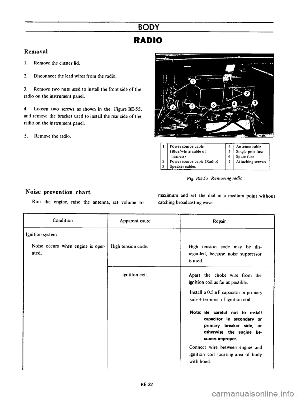
4
Loosen
two
screws
as
shown
in
the
Figure
BE
55
and
remove
the
bracket
used
to
install
the
rear
side
of
the
radio
on
the
instrument
panel
5
Remove
the
radio
Noise
prevention
chart
Run
the
engine
raise
the
antenna
set
volume
to
Condition
Apparent
cause
Ignition
system
Noise
occurs
when
engine
is
oper
High
tension
code
ated
Ignition
coil
i
O
i
M
1
iiJ
1
7
L
l
o
f
I
ft
V
r
1
1
v
I
I
t
i
J
iL
1
Power
soutee
cable
Blue
white
cable
of
harness
2
Power
source
cable
Radio
3
Speaker
cables
4
Antenna
cable
5
Single
pole
fuse
6
Spare
fuse
7
Attaching
screws
Fig
BE
55
Removing
radio
maximum
and
set
the
dial
at
a
medium
point
without
catching
broadcasting
wave
Repair
High
tension
code
may
be
dis
regarded
because
noise
suppressor
is
used
Apart
the
choke
wire
frorn
the
ignition
coil
as
far
as
possible
Install
a
0
5
uF
capacitor
in
primary
side
terminal
of
ignition
coil
Note
8e
careful
not
to
install
capacitor
in
secondary
or
primary
breaker
side
or
otherwise
the
engine
be
comes
improper
Connect
wire
between
engine
and
ignition
coil
locating
area
of
body
with
bond
BE
32