1973 DATSUN B110 parking brake
[x] Cancel search: parking brakePage 18 of 513

1
range
Park
The
operation
of
clutches
and
band
are
functionally
quite
the
same
as
in
Neutral
In
parking
however
as
the
parking
pawl
meshes
in
a
gear
whkh
is
splined
to
the
output
shaft
the
output
shaft
is
mechanically
locked
from
rotating
The
oil
discharged
from
the
oil
pump
is
fed
to
each
part
in
a
similar
manner
to
that
of
the
N
range
The
oil
having
the
line
pressure
7
which
has
been
introduced
to
the
manual
valve
V
reaches
the
I
st
2nd
shift
valve
ID
through
the
line
pressure
circuit
5
As
the
1st
2nd
shift
valve
is
forced
to
the
right
hand
side
by
the
spring
the
line
pressure
5
and
I2
actuates
the
low
and
reverse
brake
through
the
groove
Also
the
parking
pawl
engages
with
the
au
tee
teeth
of
the
oil
distributor
by
the
manual
lever
mechanically
locking
the
output
shaft
CHASSIS
Free
Lock
I
l
J
1
ri
r
r0
1
1
J
r
A
T086
Fig
AT
24
Parking
mechanism
Ceo
Clutch
Low
Band
rvo
One
Parking
RanKe
atia
rever
w
y
pawl
Front
RUI
brake
Operation
Release
clutch
Park
Reverse
2
182
on
on
Neutral
01
Low
2
458
on
Drive
02
Second
1
458
03
Top
1
000
on
2
Second
1
458
on
on
12
Second
1458
on
II
Low
2
458
on
AT
14
Page 20 of 513

R
range
Reverse
In
R
range
the
front
clutch
and
low
and
reverse
brake
are
applied
The
power
flow
is
through
the
input
shaft
front
clutch
connecting
sheU
and
to
the
sun
gear
Clockwise
rotatiun
of
the
sun
gear
causes
counterclockwise
rotation
of
the
rear
planetary
gears
With
the
connecting
drum
held
sta
tionary
by
the
low
and
reverse
brake
the
rear
planetary
gears
rotate
the
rear
internal
gear
and
drive
flange
counter
clockwise
The
rear
drive
flange
splined
to
the
output
shaft
rotates
the
output
shaft
counterclockwise
at
a
reduced
speed
with
an
increase
in
torque
for
reverse
gear
J
When
the
manual
valve
V
is
posi
tioned
at
R
range
the
oil
having
the
line
pressure
7
is
directed
to
the
line
pressure
circuits
5
and
6
The
pressure
in
the
circuit
ID
actuates
the
low
and
reverse
brake
after
being
introduced
into
the
line
pressure
cir
cuit
I2
through
the
lst
2nd
shift
valve
ID
The
pressure
in
the
circuit
operates
the
release
side
ofband
servo
and
the
front
clutch
after
being
led
to
the
line
pressure
circuit
10
through
the
2nd
3rd
shift
valve
@
The
throttle
pressure
16
and
the
line
pressure
6
which
vary
with
the
degree
of
the
depression
of
accelerator
pedal
both
act
on
the
pressure
regula
tor
valve
CD
and
press
its
valve
CD
increasing
the
line
pressure
7
In
R
range
the
governor
pressure
is
absent
making
all
sllch
valves
inoperative
as
the
lst
2nd
shift
valve
@
2nd
3rd
shift
valve
and
pressure
modifier
valve
@
CHASSIS
R
C
Fig
AT
26
Power
transmission
during
R
range
lI
a
Go
I
w
L
AT085
Fig
AT
27
Operation
of
each
mechani6m
duirng
OR
range
Clutch
low
Band
servo
One
Parking
Ran
Gear
ratio
reverse
way
pawl
Front
Rear
brake
Operation
Release
clutch
Park
on
on
Reverse
2
182
on
on
on
Neutral
01
low
2
458
nn
on
Drive
D2
Second
458
nn
on
OJ
Top
1
000
on
on
2
Second
458
nn
t2
Second
458
on
tt
low
2
458
on
on
AT
16
Page 24 of 513

CHASSIS
D
range
Low
gear
The
low
gear
in
D
range
is
somewhat
different
from
that
in
II
range
The
rear
clutch
is
applied
as
in
range
but
the
une
way
duldl
is
holding
the
connecling
drum
The
power
flow
is
the
same
as
in
11
range
That
is
the
power
flow
takes
place
through
Ihe
input
shaft
and
into
the
rear
clutch
The
input
shaft
is
splined
to
the
rear
clutch
drum
and
drives
it
Rotation
of
the
rear
clutch
dri
es
the
rear
clutch
hub
and
from
internal
gear
The
front
inlernal
gear
rotates
the
front
planetary
gears
clockwise
to
cause
the
sun
gear
to
rotate
counter
clockwise
Counterclockwise
rotation
of
the
sun
gear
turns
the
rear
planetary
gears
clockwise
With
the
Tear
plane
tary
carrier
held
stationary
by
the
one
way
clutch
the
clockwise
rotation
of
the
rear
planetary
gears
rotates
the
rear
internal
gear
and
drives
flange
clockwise
The
internal
drive
flange
is
splined
to
the
output
shaft
and
rotates
the
output
shaft
clockwise
When
the
manual
valve
is
posi
tioned
at
D
the
line
pressure
7
introduced
into
the
manual
valve
is
led
to
the
line
pressure
circuits
I
2
and
3
The
pressure
in
the
circuit
I
actuates
the
rear
clutch
and
the
gover
nor
and
at
the
same
time
operates
the
lst
2no
shift
valve
ID
to
change
the
speed
The
circuit
2
leads
to
the
second
lock
valve
@
The
circuit
3
actuales
the
2nd
3rd
shift
valve
0
for
the
2nd
3rd
speed
change
and
at
the
same
time
locks
the
second
lock
valve
@
The
throllIe
pressure
16
which
changes
with
the
degree
of
accelerator
pedal
depression
presses
the
pressure
regulator
valve
CD
and
increases
the
line
pressure
7
When
Ihe
speed
of
vehicle
has
increased
the
governor
pressure
J
5
inlroduced
from
the
line
pressure
circuit
ll
actuates
the
lst
2nd
shift
valve
ID
2nd
3rd
shift
valve
@
and
pressure
modifier
valve
@
When
the
governor
pressure
is
high
the
pressure
modifier
valve
CID
acts
in
such
a
direction
as
to
compress
C
AT080
Fig
A
T
30
Power
transmission
during
V
range
ATOP1
dmifi
Fig
AT
3
Operation
of
each
mechanism
during
VI
range
G
Clutch
Low
Band
rVo
One
Parking
Ro
reverse
woy
pawl
ratio
Front
Rear
brake
Operation
Release
clutch
Park
on
on
Reverse
2
182
on
on
on
Neutral
01
low
14
8
on
on
Drive
01
Second
1
458
on
on
03
Top
1
000
on
on
on
on
1
Second
1
458
on
on
tl
Second
1
458
on
on
1
II
low
2
458
on
on
rhe
spring
and
the
throttle
pressure
is
led
10
the
throllIe
pressure
18
This
pressure
acts
againsr
the
force
of
spring
of
the
pressure
regulator
valve
CD
and
also
against
the
Ihrollle
pres
sure
16
thus
lowering
the
line
pres
sure
7
The
governor
pressure
also
increases
with
the
speed
of
vehicle
exerting
a
pressure
on
one
side
of
the
1st
2nd
shift
valve
and
counteracts
the
throt
lie
p
ssure
19
line
pressure
I
and
the
spring
which
are
exerting
against
the
governor
pressure
Therefore
when
the
governor
pressure
exceeds
this
pressure
the
speed
is
shifted
from
Ihe
I
Sl
gear
10
the
2nd
gear
The
further
the
acceleraror
pedal
is
de
pressed
the
higher
becomes
the
throt
tle
pressure
19
increasing
the
gover
nor
pressure
and
shifting
the
speed
change
point
to
the
higher
side
AT
20
Page 26 of 513
CHASSIS
D
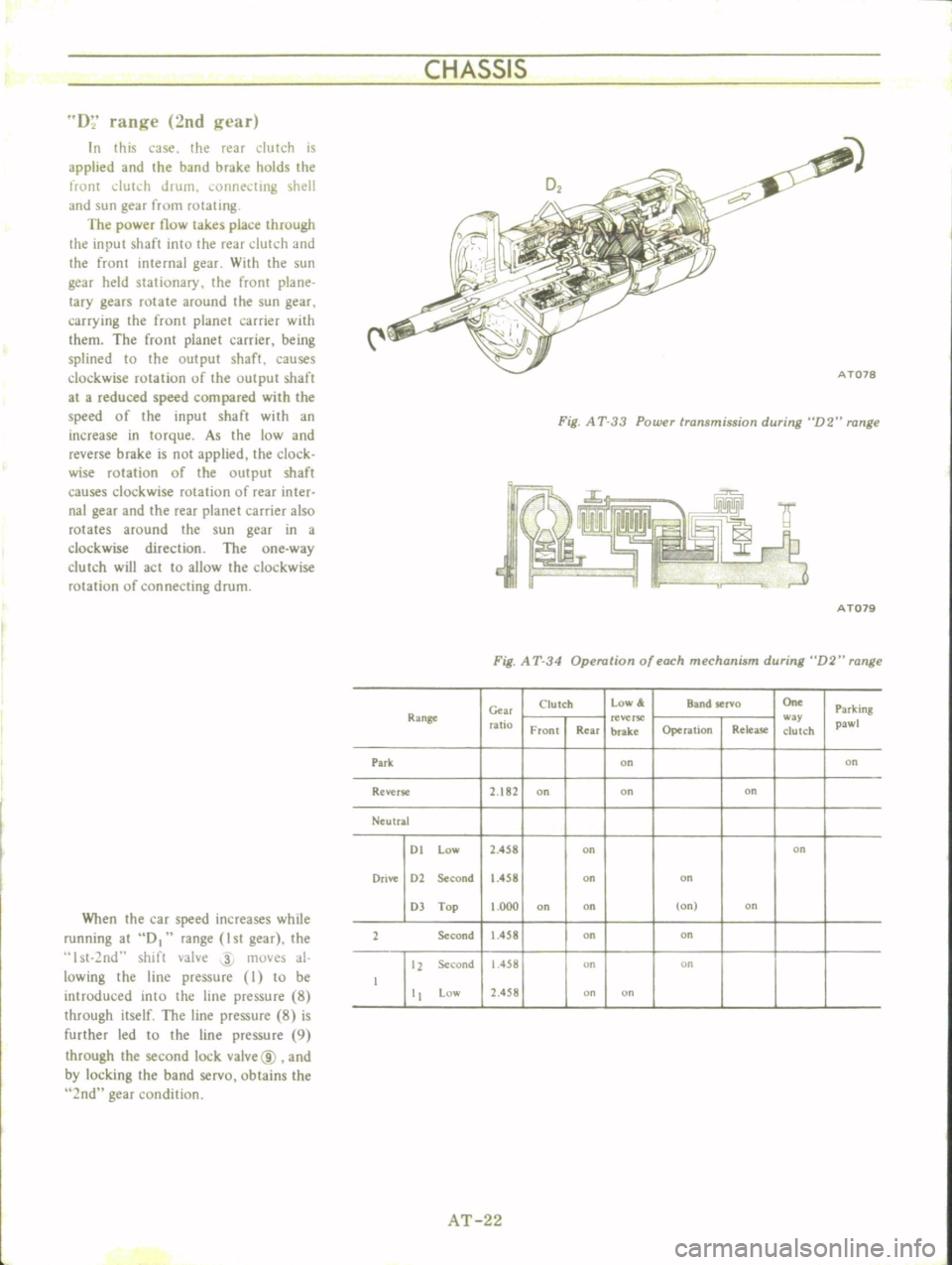
range
2nd
gl
ar
In
this
case
the
rear
dutch
is
applied
and
the
band
brake
holds
the
front
dUh
h
drum
i
onnel
ting
shell
and
sun
gear
from
rotating
The
power
now
takes
place
through
the
input
shaft
into
the
rear
dutch
and
the
front
internal
gear
WHh
the
sun
gear
held
stationary
the
fronr
plane
lacy
gears
rotate
around
the
sun
gear
carrying
the
front
planet
carrier
with
them
The
front
planet
carrier
being
splined
to
the
output
shaft
causes
clockwise
rotation
of
the
output
shafr
at
a
reduced
speed
compared
with
the
speed
of
the
input
shaft
with
an
increase
in
torque
As
the
low
and
reverse
brake
is
not
applied
the
clock
wise
rotation
of
the
output
shaft
causes
clockwise
rotation
of
rear
inter
nal
gear
and
the
rear
planet
carrier
also
rotates
around
the
sun
gear
in
a
clockwise
direction
The
one
way
clutch
will
act
to
allow
the
clockwise
rotation
of
connecting
drum
When
the
car
speed
increases
while
running
at
D
range
1st
gear
the
st
2nd
shift
valve
4
moves
al
lowing
the
line
pressure
I
to
be
introduced
into
the
line
pressure
8
through
itself
The
line
pressure
8
is
further
led
to
the
line
pressure
9
through
the
second
lock
vaIve@
and
by
locking
the
band
servo
obtains
the
2nd
gear
condition
Fig
A
T
33
Power
transmission
during
D2
range
I
r
J
ITMi
A
T079
Fig
A
T
34
Operation
of
each
mechanism
during
D2
range
C
w
Clutch
low
Band
selva
On
Parking
Range
ratio
reverse
w
y
pawl
Front
Rear
brake
Operation
Rdea5e
clutch
Park
on
on
Reverse
2
182
on
on
on
Ne
ulral
01
low
2
458
on
on
Drive
01
Second
1
458
on
on
OJ
Top
000
on
on
on
on
1
Se
cond
458
on
on
11
Second
1
458
on
on
low
1
458
on
on
AT
22
Page 28 of 513
I
CHASSIS
D
range
Top
gear
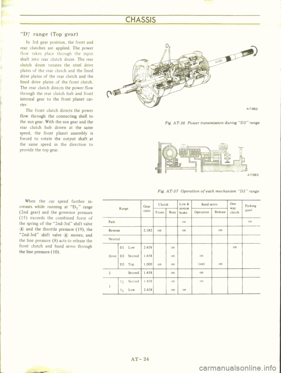
In
Jrd
gear
position
the
fornt
and
rear
dutches
are
applied
The
power
flow
takes
place
through
the
input
shaft
into
rear
dutch
drum
The
rear
clutch
drum
rotates
the
steel
drive
plates
of
the
rear
dutch
and
the
lined
drive
plates
of
the
rear
dutch
and
the
lined
drive
plates
of
the
fronl
clutch
The
rear
clutch
directs
the
power
flow
through
the
rear
clutch
hub
and
frunt
internal
gear
to
the
front
planet
car
rier
The
front
clutch
directs
the
power
now
through
the
connecting
sheU
to
the
sun
gear
With
the
sun
gear
and
the
rear
clutch
hub
driven
at
the
same
speed
the
front
planet
assembly
is
forced
to
rotate
the
output
shaft
at
the
same
speed
in
the
direction
to
provide
the
top
gear
When
the
car
speed
further
in
creases
while
running
at
02
range
2nd
gear
and
the
governor
pressore
I5
exceeds
the
combined
force
of
the
spring
of
the
2nd
3rd
shift
valve
@
and
the
throttle
pressure
19
the
2nd
3rd
shift
valve
@
moves
and
the
line
pressure
8
acts
to
release
the
front
clutch
and
band
servo
through
the
line
pressure
10
Fig
A
T
36
Power
transmission
during
D3
range
AT083
Fig
A
T
37
Operation
of
each
mechanism
D3
range
Clutch
Low
Band
servo
On
Parking
Range
c
w
ratio
Front
Rear
brake
Operalion
Release
c1ulCh
pawl
Park
00
on
Reverse
2
182
on
on
on
Ntulral
DI
low
2
458
on
on
Drive
D2
Second
1
458
on
on
OJ
Top
000
on
on
on
on
2
Second
1
458
on
on
12
Second
1
458
on
on
I
II
low
2
458
on
on
AT
24
Page 32 of 513
CHASSIS
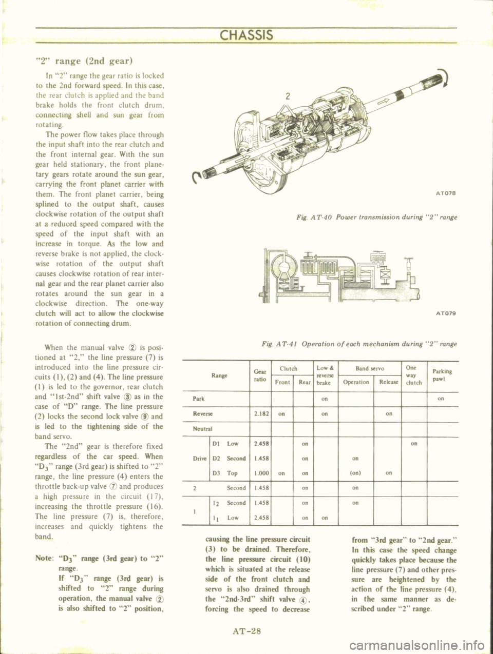
2
range
2nd
gear
In
2
range
the
gear
ratio
is
locked
to
the
2nd
forward
speed
In
this
case
the
rear
clutch
is
applied
and
the
band
brake
holds
the
front
clutch
drum
connecting
shell
and
sun
gear
from
rotating
The
power
flow
takes
place
through
the
input
shaft
into
the
rear
clutch
and
the
front
internal
gear
With
the
sun
gear
held
stationary
the
front
plane
lacy
gears
rotate
around
the
sun
gear
carrying
the
front
planet
carrier
with
them
The
front
planet
carrier
being
splined
to
the
output
shaft
causes
clockwise
rotation
of
the
output
shaft
at
a
reduced
speed
compared
with
the
speed
of
the
input
shaft
with
an
increase
in
torque
As
the
low
and
reverse
brake
is
not
applied
the
clock
wise
mlation
of
the
output
shaft
causes
clockwise
rotation
of
rear
inter
nal
gear
and
the
rear
planet
carrier
also
rotates
around
the
sun
gear
in
a
clockwise
direction
The
one
way
c1urch
will
act
to
allow
the
clockwise
rotation
of
connecting
drum
When
the
manual
valve
CV
is
posi
tioned
at
2
the
line
pressure
7
is
introduced
into
the
line
pressure
cir
cuits
I
2
and
4
The
line
pressure
I
is
led
to
the
governur
rear
dutch
and
Ist
2nd
shift
valve
ID
as
in
the
case
of
D
range
The
line
pressure
2
locks
the
second
lock
valve
@
and
is
led
to
the
tightening
side
of
the
band
servo
The
2nd
gear
is
therefore
fixed
regardless
of
the
car
speed
When
DJ
range
3rd
gear
is
shifted
to
2
range
the
line
pressure
4
enters
the
throttle
back
up
valve
IJ
and
produces
a
high
pressure
in
the
circuit
17
increasing
the
throttle
pressure
16
The
line
pressure
7
is
therefore
increases
and
quickly
tightens
the
band
Note
DJ
range
3rd
gear
to
2
range
If
DJ
range
3rd
gear
is
shifted
to
2
range
during
operation
the
manual
valve
CV
is
also
shifted
to
2
position
Fig
A
T
40
Powu
transmission
during
2
range
f
IY
9
3
AT079
Fig
A
T
41
Operation
of
each
mechanism
during
2
range
Gear
Clutch
low
Band
servo
On
Parking
Range
ratio
w
pawl
Front
Rear
brake
Operation
Relea
se
clutch
Park
on
on
Reverse
2
182
on
on
on
Neutral
I
t
Low
2
4S8
on
on
Drive
1
2
Second
1
458
on
on
1
Top
t
OOO
on
on
on
on
2
Second
1
458
on
on
12
Second
1
458
on
on
t
tt
Low
2
458
on
on
causing
the
line
pressure
circuit
3
to
be
drained
Therefore
the
line
pressure
circuit
10
which
is
situated
at
the
release
side
of
the
front
clutch
and
senro
is
also
drained
through
the
2nd
3rd
shift
valve
@
forcing
the
speed
to
decrease
from
3rd
gear
to
2nd
gear
In
this
case
the
speed
change
quickly
takes
place
because
the
line
pressure
7
and
other
pres
sure
are
heightened
by
the
action
of
the
line
pressure
4
in
the
same
manner
as
de
scribed
under
2
range
AT
28
Page 34 of 513
CHASSIS
1
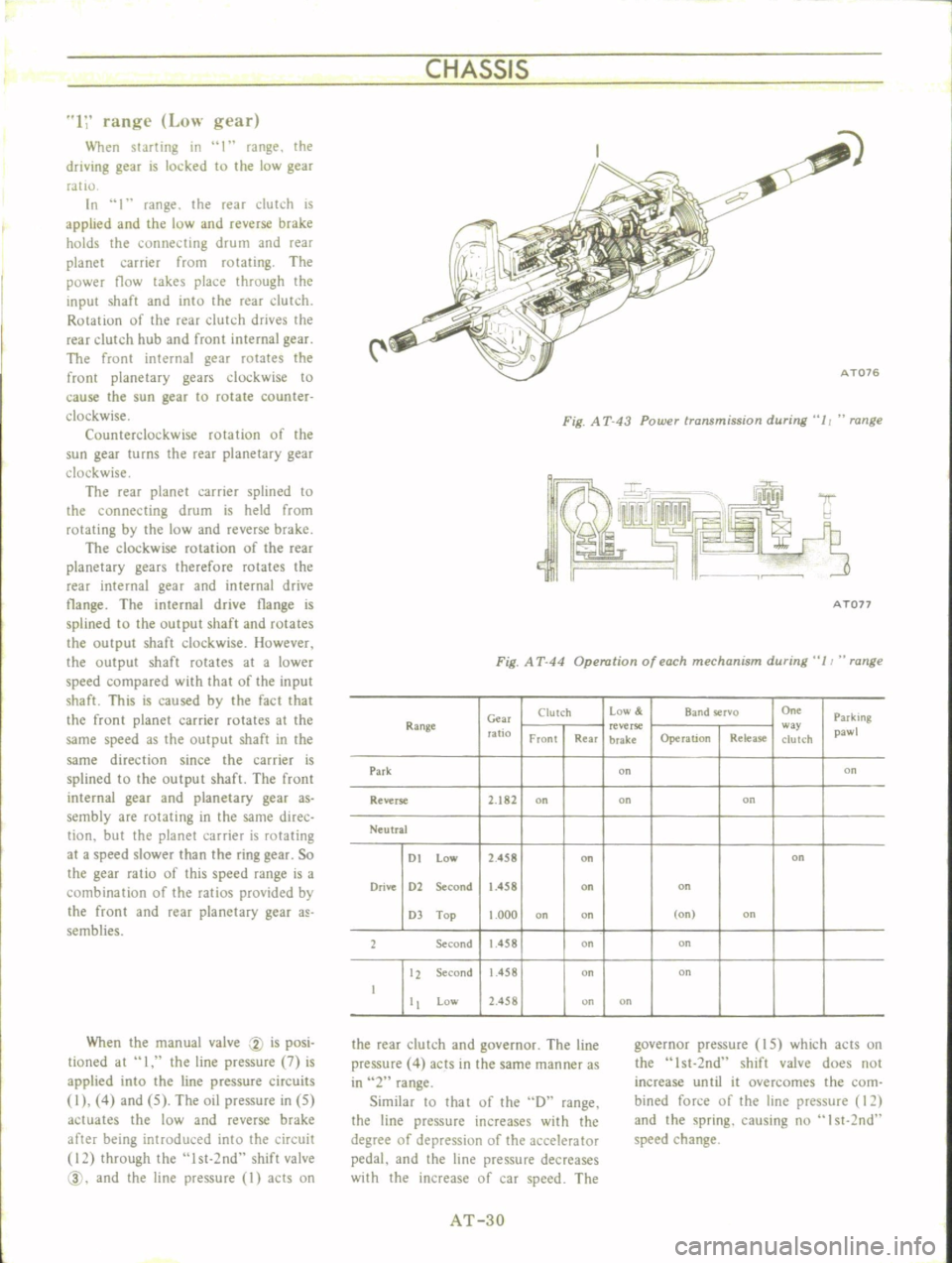
range
Low
gear
When
starting
in
I
range
the
driving
gear
is
locked
to
the
low
gear
ratIO
In
1
range
the
reaT
dutch
is
applied
and
the
low
and
reverse
brake
holds
the
connecting
drum
and
rear
planet
carrier
from
rotating
The
power
flow
takes
place
through
the
input
shaft
and
into
the
rear
dutch
Rotation
of
the
rear
clutch
drives
the
rear
clutch
hub
and
front
internal
gear
The
front
internal
gear
rotates
the
front
planetary
gears
clockwise
to
cause
the
sun
gear
to
rotate
counter
clockwise
Counterclockwise
rotation
of
the
sun
gear
turns
the
rear
planetary
gear
clockwise
The
rear
planet
carrier
splined
to
the
connecting
drum
is
held
from
rotating
by
the
low
and
reverse
brake
The
clockwise
rotation
of
the
rear
planetary
gears
therefore
rotates
the
rear
internal
gear
and
internal
drive
tlange
The
internal
drive
tlange
is
splined
to
the
output
shaft
and
rotates
the
output
shaft
clockwise
However
the
output
shaft
rotates
at
a
lower
speed
compared
with
that
of
the
input
shaft
This
is
caused
by
the
fact
that
the
front
planet
carrier
rotates
at
the
same
speed
as
the
output
shaft
in
the
same
direction
since
the
carrier
is
splined
to
the
output
shaft
The
front
internal
gear
and
planetary
gear
as
sembly
are
rotating
in
the
same
direc
tion
but
the
planet
carrier
is
rotating
at
a
speed
slower
than
the
ring
gear
So
the
gear
ratio
of
this
speed
range
is
a
combination
of
the
ratios
provided
by
the
front
and
rear
planetary
gear
a
semblies
When
the
manual
valve
CV
is
posi
tioned
at
I
the
line
pressure
7
is
applied
into
the
line
pressure
circuits
I
4
and
5
The
oil
pressure
in
5
actuates
the
low
and
reverse
brake
after
being
introduced
into
the
circuit
12
through
the
lst
2nd
shift
valve
@
and
the
line
pressure
I
acts
on
i
C
AT076
Fig
A
T
43
Power
transmission
during
11
range
A
Ton
Fig
A
T
44
Operation
of
each
mechanism
during
11
range
Clutch
Low
Band
rvo
On
Parking
Range
Gm
ratio
reverse
w
pawl
Front
Rear
brake
Operation
Release
clutch
Park
on
on
Reverse
2
182
on
on
on
Neutral
DI
low
2
458
on
on
Drive
D2
Second
1
458
on
on
D
Top
1
000
on
on
on
on
2
Second
1
458
on
on
12
Second
1
458
on
on
I
Low
2
458
on
on
the
rear
clutch
and
governor
The
line
pressure
4
acts
in
the
same
manner
as
in
2
range
Similar
10
that
of
the
D
range
the
line
pressure
increases
with
the
degree
of
depressiun
of
the
accelerator
pedal
and
the
line
pressure
decreases
with
the
increase
of
car
speed
The
governor
pressure
IS
which
acts
on
the
Ist
2nd
shift
valve
does
not
increase
until
it
overcomes
the
com
bined
force
of
the
line
pressure
12
and
the
spring
causing
nu
I
st
2nd
speed
change
AT
3D
Page 43 of 513
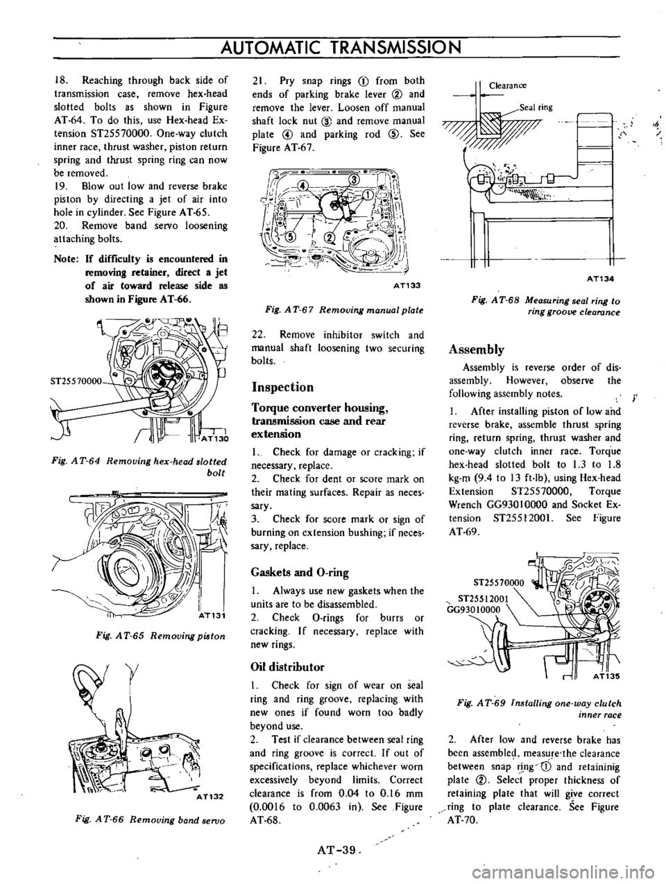
18
Reaching
through
back
side
of
transmission
case
remove
hex
head
slotted
bolts
as
shown
in
Figure
AT
64
To
do
this
use
Hex
head
Ex
tension
ST25570000
One
way
clutch
inner
race
thrust
washer
piston
return
spring
and
thrust
spring
ring
can
now
be
removed
19
Blowout
low
and
reverse
brake
piston
by
directing
a
jet
of
air
into
hole
in
cylinder
See
Figure
A
T
65
20
Remove
band
servo
loosening
attaching
bolts
Note
If
difficulty
is
encountered
in
removIng
retainer
direct
a
jet
of
air
toward
release
side
as
shown
in
Figure
AT
66
ST25570000
Fig
A
T
64
Removing
hex
head
lotted
bolt
Fig
A
T
65
Removing
pi
ton
r
AT132
Fig
A
T
66
Removing
band
seroo
AUTOMATIC
TRANSMISSION
21
Pry
snap
rings
CD
from
both
ends
of
parking
brake
lever
@
and
remove
the
lever
Loosen
off
manual
shaft
lock
nut
CID
and
remove
manual
plate
@
and
parking
rod
@
See
Figure
AT
67
Qd
i
f
W
II
4
i
n
n
r
1
K
j
e
0
H
o
i
j
j
I
j
l
m
r
JlII
2
U
r
K
F
J
r
0
f
1
r
AT133
Fig
A
T
67
Removing
manual
plate
22
Remove
inhibitor
switch
and
manual
shaft
loosening
two
securing
bolts
Inspection
Torque
converter
housing
transmission
case
and
rear
extension
1
Check
for
damage
or
cracking
if
necessary
replace
2
Check
for
dent
or
score
mark
on
their
mating
surfaces
Repair
as
neees
sary
3
Check
for
score
mark
or
sign
of
burning
on
extension
bushing
if
neces
sary
replace
Gaskets
and
O
ring
1
Always
use
new
gaskets
when
the
units
are
to
be
disassembled
2
Check
O
rings
for
burrs
or
cracking
If
necessary
replace
with
new
rings
Oil
distributor
I
Check
for
sign
of
wear
on
seal
ring
and
ring
groove
replacing
with
new
ones
if
found
worn
too
badly
beyond
use
2
Test
if
clearance
between
seal
ring
and
ring
groove
is
correct
If
out
of
specifications
replace
whichever
worn
excessively
beyond
limits
Correct
clearance
is
from
0
04
to
0
16
mm
0
0016
to
0
0063
in
See
Figure
AT
68
AT
39
Clearance
Seal
ring
F
1
I
i
h
AT134
Fig
A
T
68
Measuring
seal
ring
to
ring
groove
clearance
Assembly
Assembly
is
reverse
order
of
dis
assembly
However
observe
the
following
assembly
notes
1
After
installing
piston
of
low
and
reverse
brake
assemble
thrust
spring
ring
return
spring
thrust
washer
and
one
way
clutch
inner
race
Torque
hex
head
slotted
bolt
to
1
3
to
1
8
kg
m
94
to
13
ft
Ib
using
Hex
head
Extension
ST25570000
Torque
Wrench
GG930
1
0000
and
Socket
Ex
tension
ST25512001
See
Figure
AT
69
i
ST25570000
ST255
1
2001
GG93010000
0
rr
l
f
r
Fig
A
T
69
Installing
one
way
clutch
inner
race
2
After
low
and
reverse
brake
has
been
assemble
measure
the
clearance
between
snap
r
ng
cD
and
retaininig
plate
@
Select
proper
thickness
of
retaining
plate
that
will
gi
ve
correct
ring
to
plate
clearance
See
Figure
AT
70