1973 DATSUN B110 warning
[x] Cancel search: warningPage 125 of 513

DESCRIPTION
BRAKE
PEDAL
Removal
Inspection
Reinstallation
TANDEM
MASTER
CYLINDER
Removal
Disassembly
Inspection
Reassembly
Reinstallation
SINGLE
MASTER
CYLINDER
Removal
and
disassembly
Inspection
Reassembly
and
reinstallation
BRAKE
LINE
Removal
Inspection
Reinstallation
Brake
line
pressure
differential
warning
light
switch
FRONT
DRUM
BRAKE
cr
I
1
0
I
I
CD
BRAKE
BRAKE
CONTENTS
BR
2
BR
2
BR
2
BR
2
BR
2
BR
3
BR
3
BR
3
BR
3
BR
4
BR
4
BR
4
BR
5
BR
5
BR
5
BR
5
BR
5
BR
6
BR
6
BR
7
BR
8
Removal
and
disassembly
Inspection
Reassembly
and
reinstallation
FRONT
DISC
BRAKE
Brake
pad
Caliper
assembly
Reassembly
Reinstallation
REAR
BRAKE
Removal
and
disassembly
Inspection
Reassembly
and
reinstallation
HAND
8RAKE
Removal
Inspection
Reinstallation
ADJUSTMENT
Brake
shoe
clearance
Brake
pedal
height
Hand
brake
Bleeding
hydraulic
system
@
7
o
i
1
Brake
hose
2
Brake
master
cylinder
3
3
way
connector
4
Hand
brake
lever
5
Brake
hose
6
3
way
connector
7
Hanger
strap
8
Turn
buckle
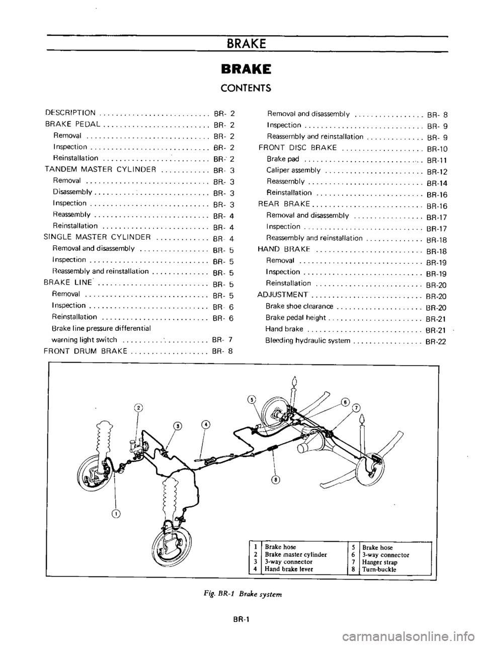
Fig
BR
l
Brake
system
BR
BR
8
BR
9
BR
9
BR
lO
BR
Il
BR
12
BR
14
BR
16
BR
16
BR
17
BR
17
BR
18
BR
18
BR
19
BR
19
BR
20
BR
20
BR
20
BR
21
BR
21
BR
22
Page 131 of 513

Tightening
torque
3
way
connector
1
5
to
1
8
kg
m
10
8
to
13
0
ft
lh
1
5
to
1
8
kg
m
10
8
to
13
0
ft
lh
1
5
to
1
8
kg
m
10
8
to
13
0
ft
lb
0
7
to
0
9
kg
m
5
1
to
6
5
ft
1b
Master
cylinder
Brake
hose
Air
bleeder
5
Fill
the
master
cylinder
brake
fluid
reservoir
with
brake
fluid
and
perform
air
bleeding
complele1y
Note
a
Do
not
use
brake
fluid
other
than
specified
b
The
specified
brake
fluid
is
used
for
both
single
and
tandem
type
master
cylinders
6
Upon
completion
of
air
bleeding
make
sure
that
the
brake
operates
correctly
and
check
the
brake
tube
and
hose
connectors
for
fluid
leaking
Fully
depress
the
brake
pedal
continue
to
depress
the
brake
pedal
for
several
seconds
and
make
sure
that
no
brake
fluid
leaks
from
any
part
of
the
brake
line
Replace
defective
part
if
required
Brake
line
pressure
differential
warning
light
switch
A
warning
light
is
located
on
the
instrument
panel
to
warn
the
driver
when
a
pressure
difference
of
13
to
17
kg
cm2
185
to
2421bJsq
in
exists
between
the
front
and
rear
b
rake
systems
A
hydraulically
actuated
warning
light
switch
is
located
in
the
engine
compartment
Both
front
and
rear
brake
systems
are
connected
to
this
switch
assembly
When
a
pressure
difference
of
13
to
17
kgJcm2
185
to
242
lbJsq
in
occurs
between
the
front
and
rear
brake
systems
the
valves
will
shuttle
toward
the
side
with
the
low
pressure
The
valve
contacts
with
the
switch
terminal
BRAKE
the
ground
circuit
for
the
warning
light
is
completed
and
thus
the
warning
light
lights
In
this
case
correct
the
hydraulic
brake
problem
and
bleed
the
brakes
Check
the
warning
light
switch
assembly
for
a
proper
operation
Check
the
switch
assembly
for
fluid
leakage
Note
Do
not
attempt
to
repair
switch
for
any
reason
replace
switch
assembly
completely
1
To
front
brake
L
H
2
From
master
cylinder
F
3
From
master
cylinder
R
4
To
rear
brake
L
B
R
M
5
To
front
brake
R
H
Fig
BR
12
Warning
light
switch
r
I
@
I
I
3
I
Valve
assembly
4
Piston
load
spring
Wire
terminal
Brake
tube
Fig
BR
13
Sectional
view
of
warning
light
switch
BR
7
Page 148 of 513

Lining
material
Front
disc
brake
Pad
width
x
thickness
x
length
Total
braking
area
Rear
brake
Lining
width
x
thickness
x
length
Total
braking
area
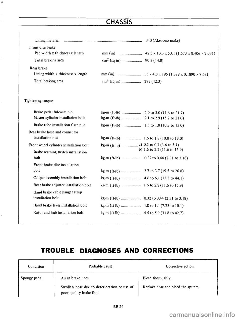
Tightening
torque
Brake
pedal
fulcrum
pin
Master
cylinder
installation
bolt
Brake
tube
installation
flare
nut
Rear
brake
hose
and
connector
installation
nut
Front
wheel
cylinder
installation
bolt
Brake
warning
switch
installation
bolt
Front
brake
disc
installation
bolt
Caliper
assembly
installation
bolt
Rear
brake
adjuster
installation
bolt
Hand
brake
cable
hanger
strap
installation
bolt
Hand
brake
lever
installation
bolt
Rotor
and
hub
installation
bolt
CHASSIS
mm
in
cm2
sq
in
mm
in
cm2
sq
in
kg
m
ft
1b
kg
m
ft
lb
kg
m
ft
lb
kg
m
ft
lb
kg
m
ft
lb
kg
m
ft
lb
kg
m
ft
lb
kg
m
ft
lb
kg
m
ft
lb
kg
m
ft
lb
kg
m
ft
lb
kg
m
ft
Ib
B40
Akebuno
make
42
5
x
10
3
x
53
I
1
673
x
0
406
x
2
091
90
3
14
0
35
x
4
8
x
195
1
378
x
0
1890
x
7
68
273
42
3
2
0
to
3
0
11
6
to
217
2
1
to
2
9
15
2
to
21
0
1
5
to
1
8
l
0
8
to
13
0
1
5
to
1
8
10
8
to
13
0
a
0
5
to
0
7
3
6
to
5
I
b
1
6
to
2
2
I
1
6
to
15
9
0
32
to
0
44
2
31
to
3
18
2
7
to
3
7
19
5
to
26
8
4
6
to
6
1
33
3
to
44
1
1
6
to
2
2
11
6
to
15
9
0
32
to
0
44
2
31
to
3
18
1
0
to
I
4
7
23
to
10
1
44
to
59
31
8
to
42
7
TROUBLE
DIAGNOSES
AND
CORRECTIONS
Condition
Spongy
pedal
Air
in
brake
lines
Probable
cause
Swollen
hose
due
to
deterioration
or
use
of
poor
quality
brake
fluid
BR
24
Corrective
action
Bleed
thoroughly
Replace
hose
and
bleed
the
system
Page 231 of 513

j
L
CD
1
II
r
1
P
r
4vc
V
4
I
o
@
@
c
ID
I
HEAD
REST
OPTION
When
installing
head
rest
on
front
seat
remove
the
plug
on
the
seat
back
and
insert
the
head
rest
supports
into
the
holes
Fig
BF
86
Head
rest
BODY
SEAT
BELT
The
two
front
seat
belts
are
of
a
three
point
type
consisting
of
lap
and
shoulder
belts
The
two
rear
seat
belts
are
of
a
tow
point
type
The
lap
belts
of
all
seats
are
provided
with
automatic
locking
retractor
In
the
front
automatic
locking
retaractor
a
belt
switch
retractor
switch
micro
switch
for
the
seat
belt
warning
system
is
built
in
Notes
a
DO
NOT
attempt
repairs
on
lap
belt
retractor
mechanisms
Replace
defective
part
with
NEW
service
replacement
parts
b
DO
NOT
replace
one
belt
of
lap
belt
or
shou
Ider
belt
set
r
l
Scating
switch
for
assistant
seat
2
Seat
belt
switch
3
Automatic
locking
retractor
4
Inhibitor
switch
for
AfT
5
Neutral
switch
for
M
T
Fig
BF
87
Seat
belt
installing
positions
BF
41
Page 242 of 513

BODY
ELECTRICAL
Note
8
When
a
fuse
is
blown
off
be
sure
to
correct
the
cause
before
installing
new
fuse
b
Be
sure
to
use
fuse
having
the
rated
capacity
Do
not
use
fuse
having
larger
capacity
i
e
20A
JOA
etc
c
Particularly
when
the
fusible
link
is
fused
replace
with
a
designated
fusible
link
Green
color
link
for
model
8110
In
comparison
with
fuse
much
higher
current
flows
through
the
fusible
link
Moreover
it
is
important
to
eliminate
the
cause
of
blown
off
fusible
link
before
replacing
d
When
fuse
is
connected
incorrectly
and
the
contact
is
loose
voltage
drops
and
heat
are
gener
ated
resulting
abnormally
operated
electrical
equip
ment
Remove
dust
or
when
oxidized
polish
with
a
fine
emery
paper
so
that
the
contact
is
improved
LlGHTING
SYSTEM
CONTENTS
HEAD
LAMP
Descri
ption
Sealed
beam
replacement
Aiming
adjustment
FRONT
PARKING
AND
TURN
SIGNAL
SIDE
FLASHER
IMARKER
LAMP
AN
D
LICENSE
LAMP
REAR
COMBINATION
LAMPS
BULB
SPECIFICATIONS
TURN
SIGNAL
AND
DIMMER
COMBINATION
SWITCH
BE
7
BE
7
BE
7
BE
8
LAMP
BE
8
BE
9
BE10
BE10
HEAD
LAMP
Description
All
weather
type
sealed
beam
2
light
system
front
lamps
are
adopted
Each
lamp
of
both
side
head
lamps
is
provided
with
high
beam
filament
for
long
range
SOW
and
low
beam
filarnent
for
dipping
40W
In
other
words
the
lamp
is
of
a
double
filament
type
Sealed
beam
replacement
I
Rernove
the
wiring
socket
from
back
of
the
head
lamp
2
Remove
the
screws
attaching
the
front
grille
to
the
radiator
core
support
Coupe
only
Remove
three
retaining
screws
and
remove
the
head
lamp
rim
All
other
than
coupe
3
Loosen
three
screws
used
to
install
the
retaining
ring
on
the
sealed
bearn
mounting
ring
and
remove
the
sealed
Removal
LIGHTING
SWITCH
Removal
HAZARD
WARNING
SWITCH
PASSING
LIGHT
SWITCH
TROUBLE
DIAGNOSES
AND
CORRECTIONS
Head
lamp
Turn
signal
lamps
Tail
and
stop
lamp
license
lamp
back
up
lamp
BE
10
BE
11
BE
11
BE
11
BE
12
BE
12
BE
12
BE
13
BE
15
i
Ii
beam
unit
4
When
installing
a
new
unit
be
sure
to
position
the
Top
mark
to
the
top
of
ring
1
2
Sealed
beam
unit
Sealed
beam
mounting
ring
3
Retaining
ring
4
Aiming
adjusting
screws
Fig
BE
18
Replacing
sealed
beam
BE
7
Page 245 of 513

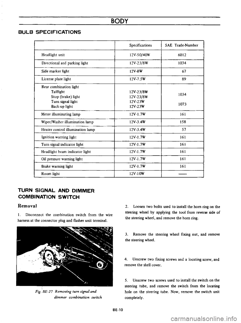
BULB
SPECIFICATIONS
Headlight
unit
Directional
and
parking
light
Side
marker
light
License
plate
light
Rear
combination
light
Taillight
Stop
brake
light
Turn
signal
light
Back
up
light
Meter
illuminating
lamp
Wiper
Washer
illumination
lamp
Heater
control
illumination
lamp
Ignition
warning
light
Turn
signal
indicator
light
Headlight
beam
indicator
light
Oil
pressure
warning
light
Brake
warning
ligh
t
Room
light
TURN
SIGNAL
AND
DIMMER
COMBINATION
SWITCH
Removal
Disconnect
the
combination
switch
from
the
wire
harness
at
the
connector
plug
and
flasher
unit
terrninal
Fig
BE
27
Removing
turn
signal
and
dimmer
combination
switch
BODY
Specifications
SAE
Trade
Number
12V
SO
40W
6012
12V
23
8W
1034
12V
8W
67
l2V
7
5W
89
12V
23
8W
1034
l2V
23
8W
l2V
23W
1073
l2V
23W
12V
I
7W
161
l2V
3
4W
158
l2V
3
4W
57
l2V
17W
161
l2V
17W
161
l2V
17W
161
l2V
17W
161
l2V
17W
161
l2V
IOW
2
Loosen
two
bolts
used
to
install
the
horn
ring
on
the
steering
wheel
by
applying
the
tool
from
reverse
side
of
the
steering
wheel
and
remove
the
horn
ring
3
Remove
the
steering
wheel
fixing
nut
and
remove
the
steering
wheel
4
Unscrew
two
fixing
screws
and
a
locating
screw
and
remove
the
shell
cover
5
Unscrew
two
screws
used
to
install
the
switch
on
the
steering
tube
and
remove
the
switch
from
the
locating
hole
on
the
steering
tube
Now
remove
the
switch
unit
completely
BE
10
Page 246 of 513

BODY
ELECTRICAL
8
G
J
r
ICENSE
LAMPS
10
0
I
I
g
N
Ap
KING
10
00
01
2
I
NATION
J
J
r
j
a
iii
a
g
Lv
F
a
G
G
Lo
o
0
I
I
m
L
J
HER
UNIT
DIMMER
SWITCH
TURN
SIONAl
SWITCH
I
I
Fig
BE
28
Circuit
diagram
for
turn
signal
and
dimmer
switch
system
LIGHTING
SWITCH
HAZARD
WARNING
SWITCH
Removal
The
hazard
lamp
system
4
way
flasher
consists
of
hazard
warning
switch
and
flasher
unit
When
the
hazard
warning
switch
is
turned
on
all
signal
lamps
flash
simultaneously
telling
other
drivers
that
the
vehicle
is
stopped
When
the
turn
signal
lamps
flash
the
pilot
lamps
on
the
instrument
panel
also
flash
telling
you
of
hazard
lamp
operation
1
Rernove
the
connector
from
back
of
the
lighting
switch
2
Depressing
the
lighting
switch
knob
turn
it
counter
clockwise
and
remove
it
3
Loosen
the
escutcheon
switch
frorn
the
cluster
lid
and
remove
the
lighting
IGNITION
SWITCH
EZ
L
I
U
I
JJ
u
HAZARD
UNIT
Ip
FLASHER
UNIT
HAZARD
WARNING
SWITCH
161
6
6
g
Q
a
ll
Zll
Zll
CE
O
a
We
a
l
e
rY
1
LEFT
SiDE
RIGHT
SIDE
Fig
BE
29
Circuit
diagram
for
hazard
lamp
system
BE
11
Page 253 of 513

BODY
METERS
AND
GAUGES
CONTENTS
CLUSTER
LID
Oescri
ption
Removal
SPEEDOMETER
Replacement
FUEL
GAUGE
AND
TEMPERATURE
GAUGE
Description
Replacement
BE
1B
BE
18
BE
18
BE
19
BE
19
BE
19
BE
19
BE
20
CLUSTER
LID
Description
The
cluster
lid
holds
various
rneters
indicators
and
clock
located
around
the
speedorneter
Printed
circuit
board
is
used
at
the
back
of
the
meter
as
shown
in
Figure
BE
38
and
the
printed
circuit
board
is
connected
with
multiple
connectors
Thus
the
meters
Can
be
inspected
and
serviced
extremely
easily
Except
for
the
speed
ometer
all
rneters
are
operated
electrically
The
fuel
gauge
and
therrnometer
are
very
reliable
and
they
are
equipped
with
bimetal
devices
F
a
o
ill
I
1
a
a
Fig
BE
34
Combination
meters
Removal
Disconnect
the
battery
terminal
depressing
the
OIL
PRESSURE
AND
IGNITION
WARNING
LAMPS
HAND
BRAKE
WARNING
LAMP
BULB
SPECIFICATIONS
TROUBLE
DIAGNOSES
AND
CORRECTIONS
Speedometer
Thermometer
and
fuel
meter
Oil
pressure
and
ignition
warning
lamps
BE
20
BE
21
BE
21
BE
22
BE
22
BE
23
BE
25
windshield
wiper
switch
lighting
switch
and
choke
lever
knobs
turn
them
counterclockwise
to
remove
Remove
the
escutcheon
2
Inserting
your
hand
into
back
of
the
cluster
lid
disconnect
the
cigarette
lighter
cable
and
turn
and
remove
the
cigarette
lighter
outer
case
3
Remove
the
radio
and
heater
control
knobs
4
Remove
the
shell
cover
from
the
steering
tube
loosen
the
screws
used
to
secure
the
meter
housing
to
the
instrument
panel
and
remove
the
cluster
lid
5
Pull
out
the
l2
pole
round
shape
connector
and
remove
the
speedometer
cable
union
nut
6
Remove
the
cluster
lid
from
the
instrument
panel
Fig
BE
35
Removing
clllSter
jd
BE
18