1973 DATSUN B110 set clock
[x] Cancel search: set clockPage 96 of 513

CHASSIS
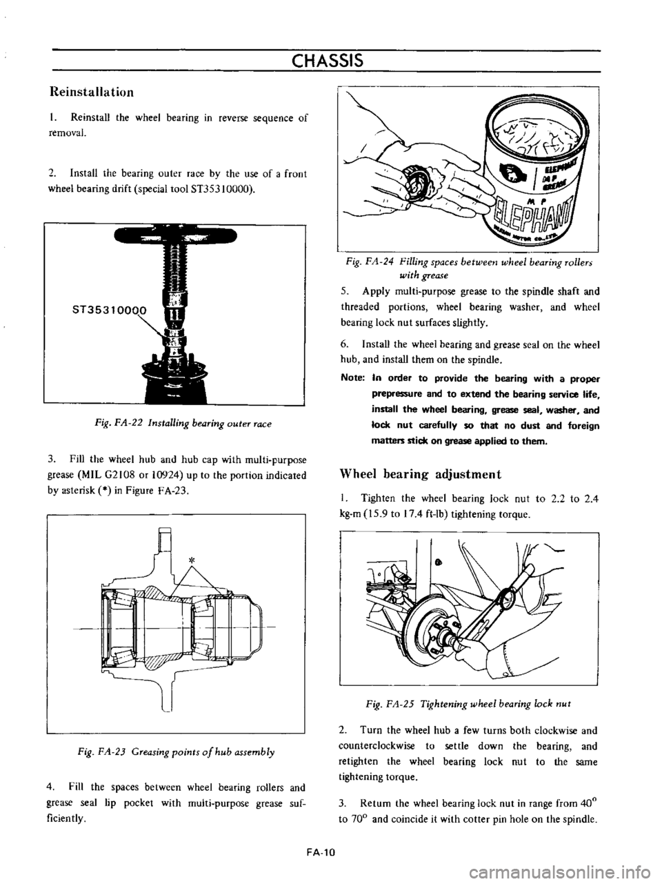
Reinstallation
Reinstall
the
wheel
bearing
in
reverse
sequence
of
removal
2
Install
the
bearing
outer
race
by
the
use
of
a
froot
wheel
bearing
drift
special
tool
ST353
10000
Fig
FA
22
Installing
bearing
outer
race
3
Fill
the
wheel
hub
and
hub
cap
with
multi
purpose
grease
MIL
G2108
or
10924
up
to
the
portion
indicated
by
asterisk
in
Figure
F
A
23
l
I
L
I
I
P
p
r
Fig
FA
23
Greasing
points
of
hub
assembly
4
Fill
the
spaces
between
wheel
bearing
rollers
and
grease
seal
lip
pocket
with
multi
purpose
grease
suf
ficiently
FA
10
Fig
FA
24
Filling
spaces
betweetJ
wheel
bearing
rollers
with
grease
5
Apply
multi
purpose
grease
to
the
spindle
shaft
and
threaded
portions
wheel
bearing
washer
and
wheel
bearing
lock
nut
surfaces
slightly
6
Install
the
wheei
bearing
and
grease
seal
on
the
wheel
hub
and
install
them
on
the
spindle
Note
In
order
to
provide
the
bearing
with
a
proper
prepressure
and
to
extend
the
bearing
service
life
install
the
wheel
bearing
grease
seal
washer
and
lock
nut
carefully
so
that
no
dust
and
foreign
matters
stick
on
grease
applied
to
them
Wheel
bearing
adjustment
I
Tighten
the
wheel
bearing
lock
nut
to
2
2
to
2
4
kg
m
15
9
to
174
ft
lb
tightening
torque
Fig
FA
25
Tightening
wheel
bearing
lock
nut
2
Turn
the
wheel
hub
a
few
turns
both
clockwise
and
counterclockwise
to
settle
down
the
bearing
and
retighten
the
wheel
bearing
lock
nut
to
the
same
tightening
torque
3
Return
the
wheel
bearing
lock
nut
in
range
from
400
to
700
and
coincide
it
with
cotter
pin
hole
on
the
spindle
Page 251 of 513

9HORN
r
I
01
8ATTERY
HI
IGI
s
ILl
C
iORN
BODY
FUSE
H
S
HORN
BUTTON
BGI
J
H
B
S
Il
I
n6lm
I
L
J
L
HORN
RELAY
Fig
BE
3l
Circuit
diagram
for
hom
syrtem
HORN
Removal
Remove
the
connector
loosen
the
fixing
nut
in
the
horn
center
and
remove
the
horn
unit
Adjustment
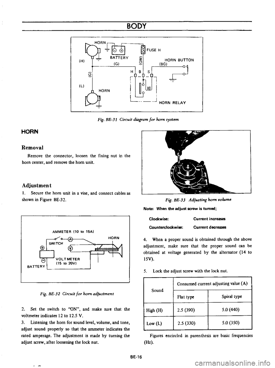
1
Secure
the
horn
unit
in
a
vise
and
connect
cables
as
shown
in
Pigure
BE
32
AMMETER
110
to
15AI
Isw
f
@
113
I
VOLTMETER
I
15
to
20VI
BATTERY
HORN
Fig
BE
32
Circuit
for
ham
adjustment
2
Set
the
switch
to
ON
and
rnake
sure
that
the
voltmeter
indicates
12
to
12
5
V
3
Listening
the
horn
for
sound
level
volurne
and
tone
adjust
sound
properly
so
that
the
amrneter
indicates
the
rated
amperage
The
adjustment
is
made
by
turning
the
adjust
screw
after
loosening
the
lock
nut
Fig
BE
33
Adjusting
hom
IIOlume
Note
When
the
adjust
screw
is
turned
Clockwise
Counterclockwise
Current
increases
Current
decreases
4
When
a
proper
sound
is
obtained
through
the
above
adjustment
rnake
sure
that
the
proper
sound
can
be
obtained
at
voltage
generated
by
the
alternator
14
to
l5V
5
Lock
the
adjust
screw
with
the
lock
nut
Consumed
current
adjusting
value
A
Sound
Plat
type
Spiral
type
High
H
2
5
390
5
0
440
Low
L
2
5
330
5
0
350
Figures
encircled
in
parenthesis
are
basic
frequencies
Hz
BE
16
Page 256 of 513

BODY
ElECTRICAL
When
the
ignition
switch
is
set
to
ON
the
ignition
wa
rning
circuit
is
closed
and
current
flows
flows
from
the
ignition
switch
to
the
warning
lamp
bulb
and
ground
through
the
regulator
When
the
engine
is
started
and
the
generator
comes
into
operation
the
generator
output
current
opposes
the
current
flowing
from
the
warning
lamp
in
effect
it
breaks
the
warning
circuit
ground
connection
and
the
lamp
goes
out
l
r
hffi
u
z
Ignition
switch
I
Q
6
I
0
c
M
1
E
8
ca
i
L
g
PI
lot
c
P
I
j
co
rt
0
relay
E
0
5
y
y
1
N
N
3
Alternator
Regulator
Fig
BE
41
Circuit
of
ignition
warning
system
HAND
BRAKE
WARNING
LAMP
This
lamp
functions
both
hand
brake
warning
larnp
and
BULB
SPECIFICATIONS
service
brake
line
pressure
differential
warning
lamp
When
a
difference
between
front
and
rear
brake
line
pressures
reaches
the
rated
range
13
to
17
kgfcm2
185
to
242
lb
sq
in
the
ground
circuit
for
the
warning
lamp
is
closed
and
the
warning
lamp
lights
IGNITION
SWITCH
WARNING
LAMP
L
E
WARNING
SWITCH
1
SERVICE
BRAKE
LINE
PRESSU
R
E
DIFFERENTIAL
WARNING
J
SWITCH
Fig
BE
42
Circuit
diagram
for
brake
warning
system
tern
Specifications
Square
type
meter
Round
type
meter
Meter
illumination
larnp
VoW
12
3
4
2
12
1
7
3
Turn
signal
pilot
lamp
VoW
12
3
4
2
12
1
7
2
Head
lamp
main
high
beam
VoW
12
3
4
I
12
17
1
pilot
lamp
Ignition
warning
lamp
VoW
123
4
I
12
17
1
Oil
pressure
warning
lamp
VoW
12
3
4
1
12
1
7
1
Hand
brake
warning
lamp
VoW
12
1
7
1
for
U
S
A
CANADA
Clock
illumination
lamp
VoW
123
4
I
12
17
2
Figure
encircled
in
parentheses
indicates
number
of
bulbs
used
BE
21
Page 314 of 513

EMISSION
CONTROL
AND
TUNE
UP
Checking
and
adjusting
dash
pot
automatic
transmission
model
only
Check
operation
of
dash
pot
It
should
not
be
cracked
or
bound
It
is
also
essential
to
check
to
be
certain
that
it
is
in
correct
adjustment
L
Check
to
be
sure
that
dash
pot
contacts
stopper
lever
when
engine
speed
reaches
1
900
to
2
000
rpm
2
Engine
should
be
slowed
down
from
3
000
to
1
000
rpm
within
a
few
seconds
Readjust
dash
pot
or
replace
it
with
a
new
one
if
it
fails
to
meet
the
above
conditions
Checking
carburetor
return
spring
Check
throttle
return
spring
for
sign
of
damage
wear
or
squareness
Discard
spring
if
found
with
any
of
above
excessively
beyond
use
Checking
choke
mechanism
choke
valve
and
linkage
1
Check
choke
valve
and
mechanism
for
free
operation
and
clean
or
replace
if
necessary
A
binding
condition
may
have
developed
from
petro
leum
gum
for
motion
on
choke
shaft
or
from
damage
2
Check
bimetal
cover
setting
position
The
index
mark
of
bimetal
cover
is
usually
aligned
at
the
middle
point
of
the
scale
Note
When
somewhat
over
choked
turn
bimetal
caver
clockwise
slightly
3
Prior
to
starting
check
to
be
sure
that
choke
valve
closes
automatically
when
pressing
down
on
accelerator
pedal
Should
it
fail
to
close
automatically
the
likelihood
is
that
fast
idle
cam
is
out
of
proper
adjustment
or
that
bimetal
is
not
properly
adjusted
calling
for
adjustment
Refer
to
Carburetor
in
Section
EF
Page
EF
15
Checking
anti
dieseling
solenoid
If
engine
will
not
stop
when
ignition
switch
is
turned
off
this
indicates
a
striking
closed
solenoid
valve
shutting
off
supply
of
fuel
to
engine
If
harness
is
in
good
condition
replace
solenoid
as
a
unit
To
replace
proceed
as
follows
Removal
and
installation
of
anti
dieseling
solenoid
Removal
Solenoid
is
cemented
at
factory
Use
special
tool
STl
91
50000
to
remove
a
solenoid
When
this
tool
is
not
effective
use
a
pair
of
pliers
to
loosen
body
out
of
position
lnstalltion
I
Before
installing
a
solenoid
it
is
essential
to
clean
all
threaded
parts
of
carburetor
and
solenoid
Supply
screws
in
holes
and
turn
them
in
two
or
three
pitches
2
First
without
disturbing
the
above
setting
coat
all
exposed
threads
with
adhensive
the
Stud
Lock
of
LOCTlTE
or
equivalent
Then
torque
screws
to
35
to
55
kg
cm
30
to
48
in
lb
using
a
special
tool
STl9150000
After
installing
anti
dieseling
solenoid
leave
the
carbu
retor
more
than
12
hours
without
operation
3
After
replacement
is
over
start
engine
and
check
to
be
sure
that
fuel
is
not
leaking
and
that
anti
dieseling
solenoid
is
in
good
condition
Notes
a
Do
not
allow
adhesive
getting
on
valve
Failure
to
follow
this
caution
would
result
in
improper
valve
performance
or
clogged
fuel
passage
b
I
n
installing
valve
use
caution
not
to
hold
body
directly
Instead
use
special
tool
tighten
ing
nuts
as
required
ET
9
Page 319 of 513

ENGINE
Adjusting
throttle
opener
setting
engine
speed
1
Connect
servo
diaphragm
vacuum
hose
directly
to
intake
manifold
connector
without
laying
through
vacuum
control
valve
2
With
negative
pressure
vacuum
in
intake
manifold
servo
diaphragm
operates
and
thus
the
primary
throttle
valve
is
opened
When
servo
diaphragm
nor
mally
operates
engine
speed
rises
reaching
1
650
to
1
850
rpm
When
engine
speed
is
not
within
this
range
turn
adjusting
screw
as
necessary
See
Figure
ET
20
l
When
engine
speed
is
lower
than
the
prescribed
range
turn
adjusting
screw
clockwise
2
When
engine
speed
is
higher
than
the
prescribed
range
turn
adjusting
screw
counterclockwise
Upon
completion
of
the
adjustment
set
adjusting
screw
lock
nut
secwely
making
sure
that
engine
speed
is
in
the
prescribed
range
@
II
I
AdJustmg
screw
2
Lock
nut
Fig
ET
20
Servo
diaphragm
adjusting
screw
Servo
diaphragm
Servo
diaphragm
stroke
Link
EC015
3
Disconnect
servo
diaphragm
vacuum
hose
from
intake
manifold
and
connect
it
to
vacuum
control
valve
Connect
vacuum
hose
of
control
valve
to
intake
manifold
normal
piping
Racing
Place
shift
lever
in
neutral
for
MfT
or
N
or
p
for
AlT
Raise
engine
speed
up
to
approximately
3
000
rpm
under
no
load
and
close
throttle
valve
by
releasing
it
from
hand
Examine
engine
speed
to
see
whether
it
falls
to
idling
speed
I
When
engine
revolution
rails
to
idling
speed
See
Figure
ET
24
The
primary
throttle
valve
is
opened
by
the
link
connected
to
it
When
the
engine
speed
is
increased
to
approximately
3
000
rpm
and
lowered
natually
from
this
speed
changes
in
servo
diaphragm
link
stroke
manifold
vacuum
and
en
ine
speed
are
as
shown
in
Figure
ET
21
o
u
u
0
2
Se
o
diaphragm
link
stroke
I
u
2
Full
0
o
Intake
manifold
vacuum
u
c
E
c
O
3000
c
e
Engine
speed
2000
g
i
c
1000
T
j
Time
second
Fig
ET
21
Changes
in
servo
diaphragm
link
stroke
intake
manifold
vacuum
and
engine
speed
ET
14
Page 321 of 513

ENGINE
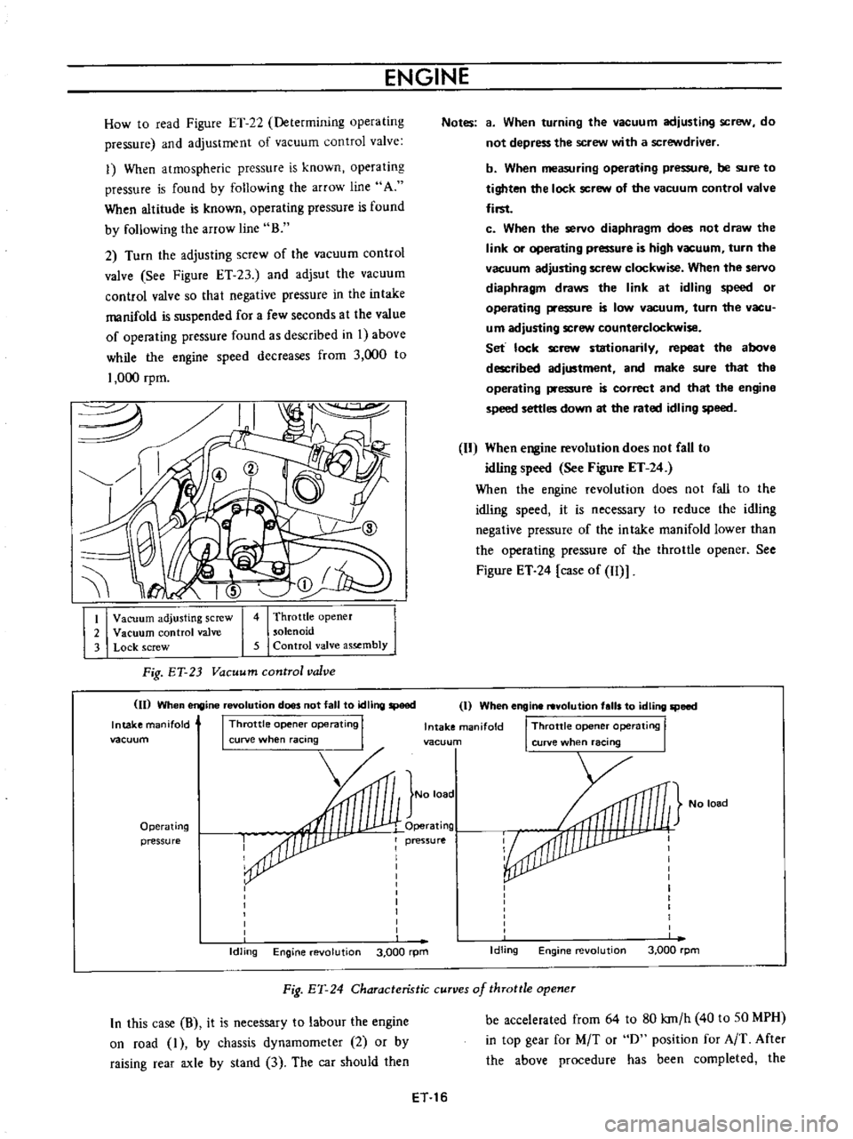
How
to
read
Figure
ET
22
Determining
operating
pressure
and
adjustment
of
vacuum
control
valve
1
When
atmospheric
pressure
is
known
operating
pressure
is
found
by
following
the
arrow
line
A
When
altitude
is
known
operating
pressure
is
found
by
following
the
arroW
line
B
2
Turn
the
adjusting
screw
of
the
vacuum
control
valve
See
Figure
ET
23
and
adjsut
the
vacuum
control
valve
so
that
negative
pressure
in
the
intake
manifold
is
suspended
for
a
few
seconds
at
the
value
of
operating
pressure
found
as
described
in
I
above
while
the
engine
speed
decreases
from
3
000
to
1
000
rpm
I
Vacuum
adjusting
screw
2
Vacuum
control
valve
3
Lock
screw
4
Throttle
opener
solenoid
5
Control
valve
assembly
Fig
ET
23
Vacuum
control
valve
II
When
engine
revolution
does
not
fall
to
tdling
speed
Intake
manifold
I
Throttle
opene
operating
I
vacuum
curve
when
racing
Operating
pressure
Idling
Engine
evolution
3
000
rpm
Notes
a
When
turning
the
vacuum
adjusting
scre
N
do
not
depress
the
screw
with
a
screwdriver
b
When
measuring
operating
pressure
be
sure
to
tighten
the
lock
screw
of
the
vacuum
control
valve
first
c
When
the
servo
diaphragm
does
not
draw
the
link
or
operating
pressure
is
high
vacuum
turn
the
vacuum
adjusting
screw
clockwise
When
the
servo
diaphragm
draws
the
link
at
idling
speed
or
operating
pressure
is
low
vacuum
turn
the
vacu
um
adjusting
screw
counterclockwise
Set
lock
screw
stationarily
repeat
the
above
described
adjustment
and
make
sure
that
tho
operating
pressure
is
correct
and
that
the
engine
speed
settles
down
at
the
rated
idling
speed
When
engine
revolution
does
not
CaU
to
idling
speed
See
Figure
ET
24
When
the
engine
revolution
does
not
fall
to
the
idling
speed
it
is
necessary
to
reduce
the
idling
negative
pressure
of
the
intake
manifold
lower
than
the
operating
pressure
of
the
throttle
opener
See
Figure
ET
24
case
of
Il
Il
I
When
engine
revolution
falls
to
idling
speed
Intake
manifold
I
Throttle
opene
operating
I
vacuun
curve
when
racing
No
load
No
load
Operating
pressure
I
I
I
I
I
I
I
I
I
Idling
Engine
revolution
3
000
rpm
Fig
EY
24
Characteristic
curves
of
throttle
opener
In
this
case
B
it
is
necessary
to
labour
the
engine
on
road
I
by
chassis
dynamometer
2
or
by
raising
rear
axle
by
stand
3
The
car
should
then
be
accelerated
from
64
to
80
kro
h
40
to
SO
MPH
in
top
gear
for
M
T
or
0
position
for
A
T
After
the
above
procedure
has
been
completed
the
ET
16
Page 408 of 513

FUEL
SYSTEM
c
Oke
valve
1
Or
Rubber
band
Fig
EF
2B
Adjusting
choke
unloadeT
Hi
metal
setting
Measurement
of
bi
metal
heater
resistance
Install
the
bi
metal
cover
in
place
on
the
carburetor
Make
sure
that
the
resistance
across
the
terminal
and
the
carburetor
body
is
in
the
range
from
8
6
to
9
0
ohms
Measure
the
resistance
without
electric
current
through
the
heater
and
at
about
210e
700F
Note
Use
an
accurate
measuring
instrument
such
as
a
wheatstone
bridge
2
Bi
metal
cover
setting
Position
the
hi
metal
cover
until
the
index
mark
is
aligned
at
the
middle
point
of
the
scale
Note
When
somewhat
over
choked
set
bi
metal
cover
after
turning
it
clockwise
slightly
Fig
EF
29
Setting
hi
metal
cover
EF
17
Page 445 of 513

ENGINE
ElECTRICAL
SYSTEM
Ambient
temperature
Rated
regulating
voltage
roC
OF
V
10
14
14
6
to
15
6
0
32
14
45
to
15
45
10
50
14
3
to
15
3
20
68
14
15
to
15
15
30
86
14
0
to
15
0
40
104
13
85
to
14
85
Note
8
Do
not
measure
voltage
immediately
after
driv
ing
Do
this
while
regulator
is
cold
b
To
measure
voltage
raise
engine
speed
gradual
ly
from
idling
to
rated
speed
c
Voltage
may
be
approximately
O
3V
higher
than
the
rated
for
two
to
three
minutes
after
engine
is
started
or
more
specifically
when
regulator
becomes
self
heated
Measurements
should
then
be
made
within
one
minute
after
starting
engine
or
when
regulator
is
cold
d
The
regulator
is
of
a
temperature
compensating
type
Before
measuring
voltage
be
sure
to
meas
ure
surrounding
temperature
and
correct
measure
ments
according
to
the
table
in
the
left
hand
side
ADJUSTMENT
Voltage
regulator
As
the
result
of
above
measurement
when
the
regu
lating
voltage
is
deviated
from
the
rated
value
adjust
the
regulator
in
accordance
with
the
following
instructions
I
Inspect
contact
surface
and
if
rough
lightly
polish
the
surface
with
fine
emery
paper
500
or
600
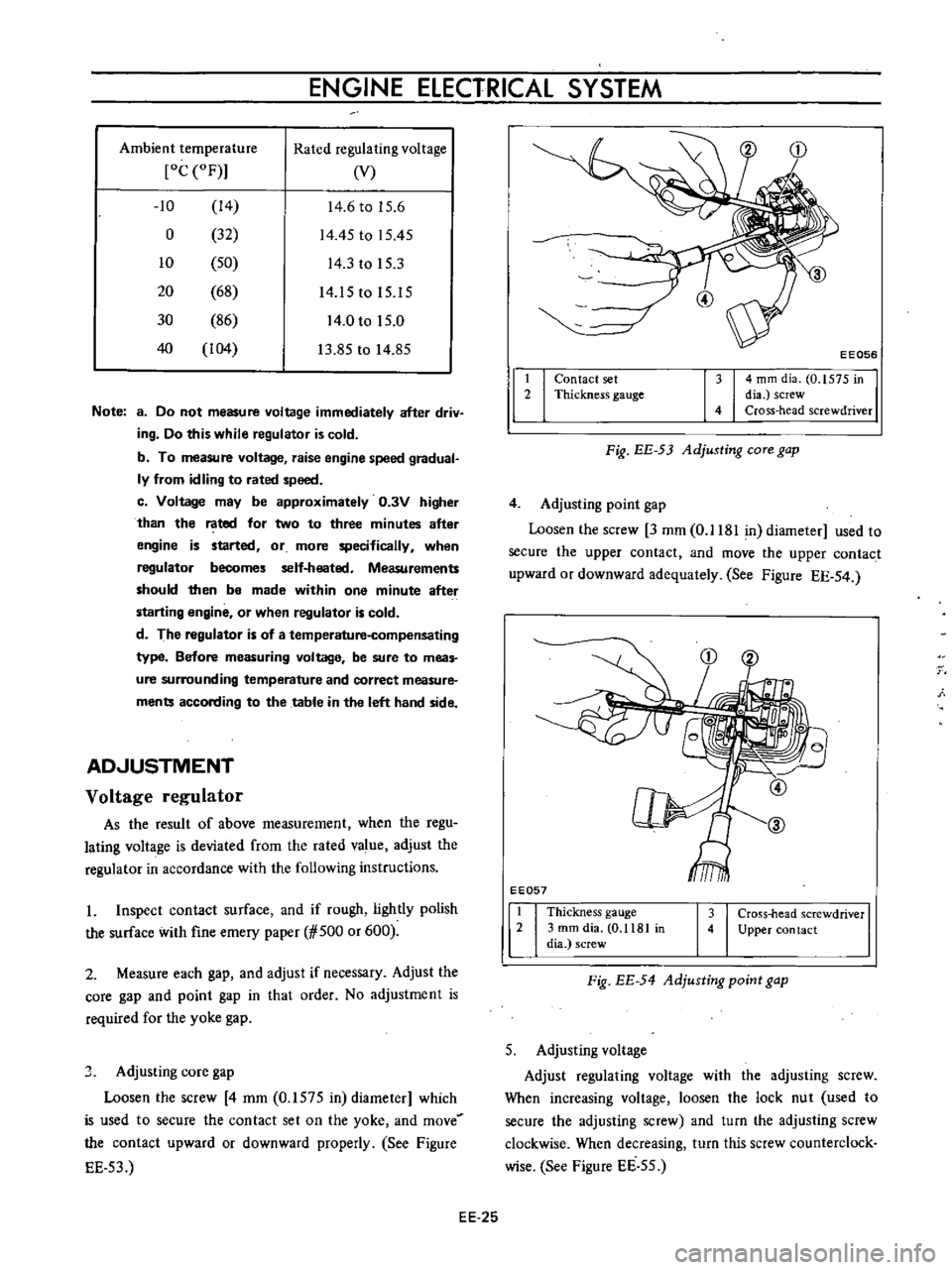
2
Measure
each
gap
and
adjust
if
necessary
Adjust
the
core
gap
and
point
gap
in
that
order
No
adjustment
is
required
for
the
yoke
gap
J
Adjusting
core
gap
Loosen
the
screw
4
mm
0
1575
in
diameter
which
is
used
to
secure
the
contact
set
on
the
yoke
and
move
the
contact
upward
or
downward
properly
See
Figure
EE
53
t
2
I
I
EE056
4
mm
dia
0
1575
in
dia
screw
Cross
head
screwdriver
Contact
set
Thickness
gauge
Fig
EE
53
Adjusting
COTe
gap
4
Adjusting
point
gap
Loosen
the
screw
3
mm
0
1181
in
diameter
used
to
secure
the
upper
contact
and
move
the
upper
contact
upward
or
downward
adequately
See
Figure
EE
54
EE057
1
Thickness
gauge
2
3
mm
dia
0
1181
in
dia
screw
3
Cross
head
screwdriver
4
Upper
con
tact
Fig
EE
54
Adjusting
point
gap
5
Adjusting
voltage
Adjust
regulating
voltage
with
the
adjusting
screw
When
increasing
voltage
loosen
the
lock
nut
used
to
secure
the
adjusting
screw
and
turn
the
adjusting
screw
clockwise
When
decreasing
turn
this
screw
counterclock
wise
See
Figure
EE
55
EE
25