1973 DATSUN B110 wheel torque
[x] Cancel search: wheel torquePage 45 of 513
Adjustment
of
front
end
play
Select
front
clutch
thrust
washer
by
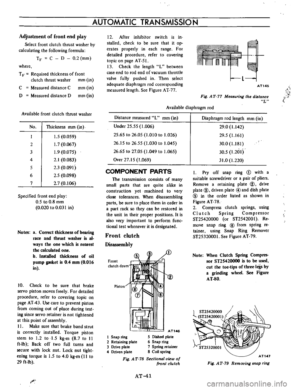
calculating
the
following
formula
TF
C
D
0
2
mm
where
T
F
Required
thickness
of
front
clutch
thrust
washer
mm
in
C
Measured
distance
C
mm
in
D
Measured
distance
D
mm
in
Available
front
clutch
thrust
washer
No
Thickness
mm
in
I
J
5
0
059
2
1
7
0
067
3
1
9
0
075
4
2
1
0
083
5
2
3
0
091
6
2
5
0
098
7
2
7
0
106
Specified
front
end
play
0
5
to
0
8
mm
0
020
to
0
031
in
Notes
a
Correct
thickness
of
bearing
race
and
thrust
washer
is
al
ways
the
one
which
is
nearest
the
calculated
one
b
Installed
thickness
of
oil
pump
gasket
is
0
4
mm
0
016
in
10
Check
to
be
sure
that
brake
servo
piston
moves
freely
For
detailed
procedure
refer
to
covering
topic
on
page
AT
43
Use
care
to
prevent
piston
from
coming
out
of
place
during
test
ing
since
servo
retainer
is
not
tightened
at
this
point
of
assembly
II
Make
sure
that
brake
band
strut
is
correctly
installed
Torque
piston
stem
to
1
2
to
1
5
kg
m
8
7
to
II
ft
lb
Back
off
two
full
turns
and
secure
with
lock
nut
Lock
nut
tight
ening
torque
is
1
5
to
4
0
kg
m
I
I
to
29
ft
Ib
AUTOMATIC
TRANSMISSION
I
2
After
inhibitor
switch
is
in
stalled
check
to
be
sure
that
it
op
erates
properly
in
each
range
For
detailed
procedure
refer
to
covering
topic
on
page
AT
51
13
Check
the
length
L
between
case
end
to
rod
end
of
vacuum
throttle
valve
fully
pushed
in
Then
select
adequate
diaphragm
rod
corresponding
measured
length
See
Figure
AT
77
m
rj
I
L
1
AT145
i
Fig
AT
77
Measuring
the
distance
L
Available
diaphragm
rod
Distance
measured
L
mm
in
Under
25
55
1
006
25
65
to
26
05
1
010
to
1
026
26
15
to
26
55
1
030
to
1
045
26
65
to
27
05
1
049
to
1
065
Over
27
15
1
069
COMPONENT
PARTS
The
transmission
consists
of
many
small
parts
that
are
quite
alike
in
construction
yet
machined
to
very
close
tolerances
When
disassembling
parts
be
sure
to
place
them
in
order
in
a
part
rack
so
they
can
be
restored
in
the
unit
in
their
proper
positions
It
is
also
very
important
to
perform
func
tional
test
whenever
it
is
designated
Front
clutch
Disassembly
Front
clutch
drum
Piston
1
AT146
1
Snap
ring
S
Dished
plate
2
Retaining
plate
6
Snap
ring
3
Drive
plate
7
Spring
retainer
4
Driven
plate
8
Coil
spring
Fig
AT
78
S
ctional
v
w
of
front
clutch
AT
41
Diaphragm
rod
length
mm
in
29
0
1
142
29
5
1
161
30
0
1
181
30
5
1
2
1I
31
0
1
220
I
Pry
off
snap
ring
D
with
a
suitable
screwdriver
or
a
pair
of
pliers
Remove
a
retaining
plate
@
drive
plate
@
driven
plate
@and
dish
plate
@
in
the
order
listed
as
shown
in
Figure
AT
78
2
Compress
clutch
springs
using
Clutch
Spring
Compressor
ST25420000
or
ST2542001
Re
move
snap
ring
@
from
spring
re
tainer
using
Snap
Ring
Remover
ST25320001
See
Figure
AT
79
Note
When
Clutch
Spring
Compres
sor
STIS420000
is
to
be
used
cut
the
toe
tips
of
threeloigs
by
a
grinding
wheel
See
Figure
AT
80
AT
1
Fig
AT
79
RemoL
ing
snap
ring
Page 55 of 513

c
Inspection
and
adJu
Stmenf
trouble
first
check
the
linhge
f
no
1
i
jI
fect
is
found
in
the
lin1
age
check
of
manu
a
l
liiiJ
i
the
inhibitor
switch
Th
d
1F
aI
S
t
th
I
I
f
e
a
JU
i
J
u
epara
e
e
range
se
eet
ever
rom
Iy
important
ii
s3
ns
etion
of
oil
the
lower
shift
rod
and
turn
the
range
1
level
for
the
automatiC
tran
smission
select
lever
to
N
Therefore
great
care
should
be
exer
Note
In
the
position
N
the
slot
of
cised
because
defective
adjustment
will
the
manual
shaft
is
vertical
result
in
the
breakdown
of
the
trans
By
the
use
of
the
tester
check
the
two
bIack
yellow
BY
wires
from
the
inhibitor
switch
in
the
ranges
N
and
P
and
the
two
red
bIack
RB
wires
in
the
range
R
for
continuity
Turn
range
select
lever
to
both
directions
from
each
lever
set
position
and
check
each
continuity
range
It
is
normal
if
the
electricity
is
on
while
the
lever
is
within
an
angle
of
about
3
0
on
both
sides
from
each
lever
set
line
How
ever
if
its
continuity
range
is
obvi
ously
unequal
on
both
sides
the
adjustment
is
required
f
any
malfunction
is
found
un
screw
the
fastening
nut
of
the
range
selector
lever
and
two
fastening
bolts
of
the
switch
body
and
then
remove
the
machine
screw
under
the
switch
body
Adjust
the
manual
shaft
correct
ly
to
the
position
N
by
means
of
the
selector
lever
When
the
slot
of
the
shaft
becomes
vertical
the
detent
works
to
position
the
shaft
correctly
with
a
click
sound
Move
the
switch
slightly
aside
so
that
the
screw
hole
will
be
aligned
with
the
pin
hole
of
the
internal
rotor
combined
with
the
manual
shaft
and
check
their
alignment
by
inserting
a
1
5
0101
0
0591
in
diameter
pin
into
the
holes
If
the
alignment
is
made
correct
1
5ten
the
switch
body
with
the
bolts
pull
out
the
pin
and
tighten
up
the
screw
again
into
the
hole
and
fasten
the
selector
lever
as
before
Check
over
again
the
continuity
with
the
tester
If
the
malfunction
still
remains
replace
the
inhibitor
switch
mission
Inspection
Pull
the
selector
lever
toward
you
and
turn
it
so
far
as
p
to
1
range
where
clicks
will
be
felt
by
hand
This
is
the
detent
of
manual
valve
in
the
body
and
indicates
the
correct
posi
tion
of
the
lever
Inspect
whether
the
pointer
of
selector
dial
corresponds
to
this
point
and
also
whether
the
lever
comes
in
alignment
with
the
stepping
of
posi
tion
plate
when
it
is
released
Adjustment
This
procedure
can
be
accom
plished
by
referring
to
Removal
and
nstallation
Checking
and
adjusting
inhibitor
switch
The
inhibitor
switch
serves
to
light
the
reverse
lamp
in
the
range
R
of
the
transmission
operation
and
also
to
rotate
the
starter
motor
in
the
ranges
N
and
P
j
r@
I
If
r
f
B
@
I
Jt
@
@
c
v@
i
r
fji
AT109
1
Inhibitor
switch
2
Manual
shaft
3
Washer
4
Nut
5
Manual
plate
Fig
AT
II
0
Con
truction
of
inhibitor
witch
6
Washer
7
Nut
8
Inhibitor
switch
9
Range
select
lever
Check
whether
the
reverse
lamp
and
the
starter
motor
operate
normal
ly
in
these
ranges
If
there
is
any
t
ki
A
mm
ATIC
TRANSMISSION
STALL
TEST
The
purpose
of
this
test
is
to
check
the
transmission
and
engine
for
trou
ble
by
measuring
the
maximwn
num
bers
of
revolutions
of
the
engine
while
vehicle
is
held
in
a
stalled
condition
and
the
carburetor
is
in
full
throttle
operation
with
the
selector
lever
in
AT
51
rang
s
D
2
and
I
respectively
and
by
com
pairing
the
measured
re
sults
with
the
standard
values
Standard
stall
revolution
1
750
to
2
000
rpm
Components
to
be
tested
and
test
items
1
Clutches
brake
and
band
in
trans
mission
for
slipping
2
Torque
converter
for
function
3
Engine
for
overall
property
Stall
test
procedures
Before
testing
check
the
enigne
oil
and
torque
converter
oil
warm
up
the
engine
cooling
water
to
the
suitable
temperature
by
warming
up
ope
ration
at
1
200
rpm
with
the
selector
lever
in
the
range
P
for
several
minutes
and
warm
up
the
torque
converter
oil
to
the
suitable
temperature
60
to
IOOoC
140
to
2120F
1
Mount
the
engine
tachometer
at
a
location
that
allows
good
visibility
from
the
driver
s
seat
and
put
a
mark
on
specified
revolutions
on
the
meter
2
Secure
the
front
and
rear
wheels
completely
with
chocks
and
apply
the
hand
brake
Be
sure
to
depress
the
brake
pedal
firmly
with
the
left
foot
before
depressing
down
the
accelerator
pedal
3
Throw
the
selector
lever
into
the
range
D
4
Slowly
depress
the
accelerator
pedal
down
till
the
throttle
valve
is
fully
opened
Quickly
read
and
record
the
engine
revolution
when
the
engine
begins
to
rotate
steadily
and
then
release
the
accelerator
pedal
5
Turn
the
selector
lever
into
N
and
operate
the
enigne
at
approxi
mately
1
200
rpm
for
more
than
one
minute
to
cool
down
the
torque
con
verter
oil
and
coolant
6
Make
similar
stall
tests
in
the
ranges
2
I
and
R
Note
The
stall
test
operation
as
spec
ified
in
the
item
4
should
be
made
within
five
seconds
If
it
takes
too
long
the
oil
deterio
rates
and
the
clutches
brake
Page 83 of 513
CHASSIS
TROUBLE
DIAGNOSES
AND
CORRECTIONS
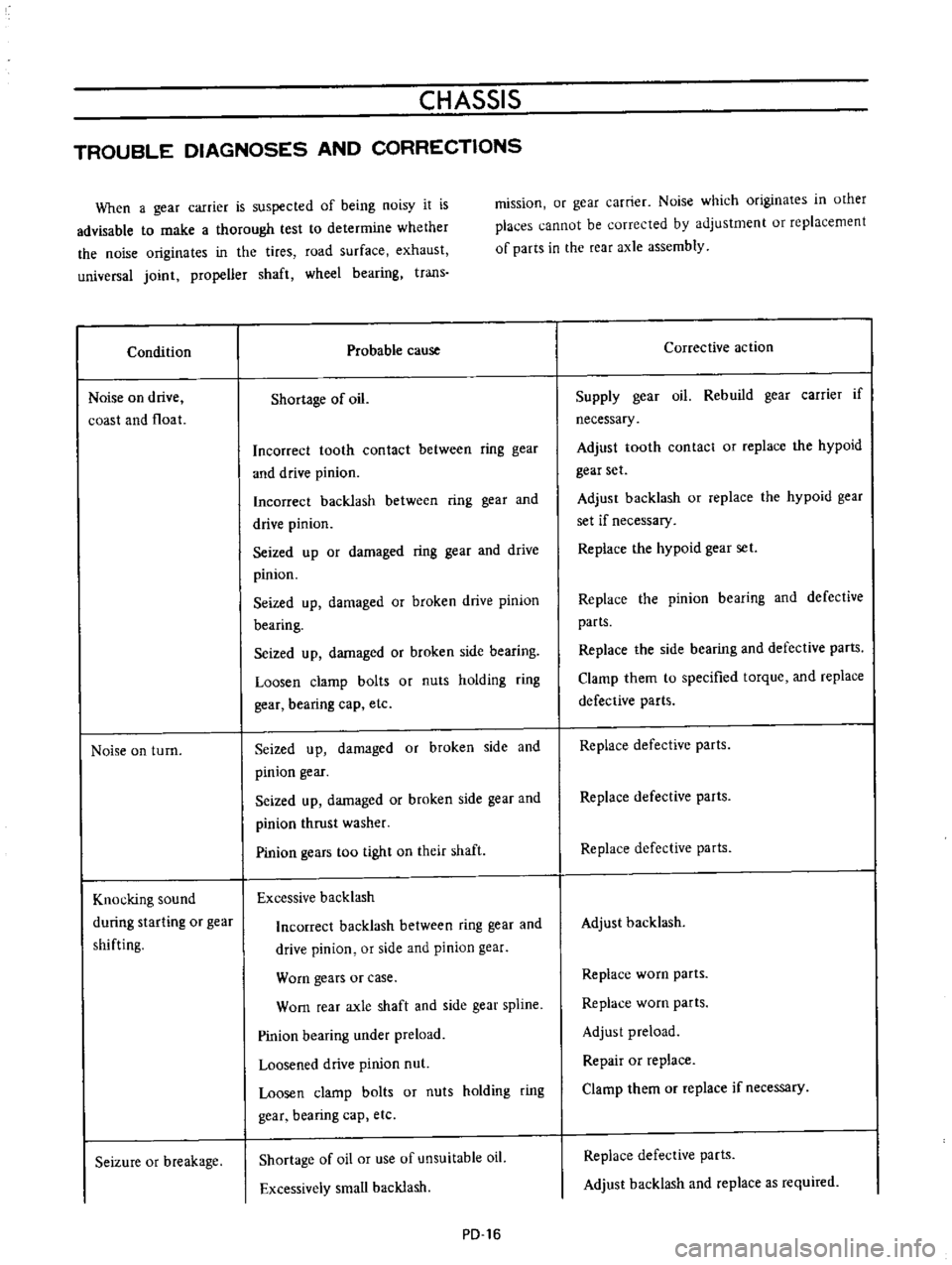
When
a
gear
carrier
is
suspected
of
being
noisy
it
is
advisable
to
make
a
thorough
test
to
determine
whether
the
noise
originates
in
the
tires
road
surface
exhaust
universal
joint
propeller
shaft
wheel
bearing
trans
Condition
Noise
on
drive
coast
and
float
Noise
on
turn
Knocking
sound
during
starting
or
gear
shifting
Seizure
or
breakage
mission
or
gear
carrier
Noise
which
originates
in
other
places
cannot
be
corrected
by
adjustment
or
replacement
of
parts
in
the
rear
axle
assembly
Probable
cause
Shortage
of
oil
Incorrect
tooth
contact
between
ring
gear
and
drive
pinion
Incorrect
backlash
between
ring
gear
and
drive
pinion
Seized
up
or
damaged
ring
gear
and
drive
pinion
Seized
up
damaged
or
broken
drive
pinion
bearing
Seized
up
damaged
or
broken
side
bearing
Loosen
clamp
bolts
or
nuts
holding
ring
gear
bearing
cap
etc
Seized
up
damaged
or
broken
side
and
pinion
gear
I
Seized
up
damaged
or
broken
side
gear
and
pinion
thrust
washer
Pinion
gears
too
tight
on
their
shaft
Excessive
backlash
Incorrect
backlash
between
ring
gear
and
drive
pinion
or
side
and
pinion
gear
Worn
gears
or
case
Worn
rear
axle
shaft
and
side
gear
spline
Pinion
bearing
under
preload
Loosened
drive
pinion
nut
Loosen
clamp
bolts
or
nuts
holding
ring
gear
bearing
cap
etc
Shortage
of
oil
or
use
of
unsuitable
oil
Excessively
small
backlash
PD
16
Corrective
action
Supply
gear
oil
Rebuild
gear
carrier
if
necessary
Adjust
tooth
contact
or
replace
the
hypoid
gear
set
Adjust
backlash
or
replace
the
hypoid
gear
set
if
necessary
Replace
the
hypoid
gear
set
Replace
the
pinion
bearing
and
defective
parts
Replace
the
side
bearing
and
defective
parts
Clamp
them
to
specified
torque
and
replace
defective
parts
Replace
defective
parts
Replace
defective
parts
Replace
defective
parts
Adjust
backlash
Replace
worn
parts
Replace
worn
parts
Adjust
preload
Repair
or
replace
Clamp
them
or
replace
if
necessary
Replace
defective
parts
Adjust
backlash
and
replace
as
required
Page 92 of 513

CHASSIS
Tightening
torque
of
front
suspension
cross
member
and
body
is
3
2
to
4
0
kg
m
23
1
to
28
9
ft
Ib
5
Tightening
torque
of
bolt
used
to
secure
the
upper
portion
of
the
strut
assembly
on
the
body
is
1
6
to
2
1
kg
m
11
6
to
15
2ft
lb
FRONT
AXLE
Removal
I
Jack
up
the
vehicle
remove
the
wheel
and
discon
nect
the
brake
hose
at
the
strut
outer
casing
bracket
unit
For
details
see
Removal
of
front
axle
and
suspension
assembly
2
Remove
the
brake
caliper
installation
bolts
and
remove
the
caliper
assembly
Disc
type
brake
3
Remove
the
brake
druOL
Drum
type
brake
4
Remove
the
hub
cap
with
a
flal
headed
screwdriver
or
other
proper
tool
and
hammer
Be
sure
to
tap
lightly
5
Remove
cotter
pin
from
the
wheel
bearing
lock
nut
and
remove
the
lock
nut
6
With
the
wheel
bearing
washer
and
wheel
bearing
installed
on
the
wheel
hub
remove
the
wheel
hub
from
the
spindle
In
the
case
of
a
disc
type
brake
the
wheel
hub
may
be
removed
with
the
disc
rotor
installed
on
the
wheel
hub
Fig
FA
17
Removing
wheel
hub
7
Remove
the
return
spring
and
brake
shoes
remove
brake
disc
assembly
installation
bolts
and
remove
the
brake
disc
assembly
from
the
spindle
Drum
type
brake
Fig
FA
IS
Removing
brake
disc
a
ssembly
8
Remove
baffle
plate
set
screws
and
remove
the
baffle
plate
Disc
type
brake
Fig
FA
19
Removingbaffleplate
9
Utilizing
two
grooves
inside
the
wheel
hub
tap
and
remove
the
wheel
bearing
outer
race
from
the
hub
Fig
FA
20
Removing
wheel
bearing
outer
race
FA
6
Page 96 of 513
CHASSIS
Reinstallation
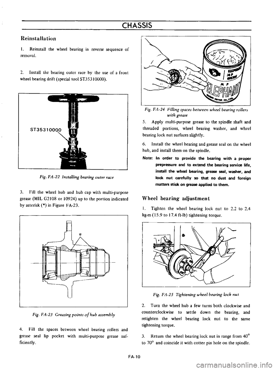
Reinstall
the
wheel
bearing
in
reverse
sequence
of
removal
2
Install
the
bearing
outer
race
by
the
use
of
a
froot
wheel
bearing
drift
special
tool
ST353
10000
Fig
FA
22
Installing
bearing
outer
race
3
Fill
the
wheel
hub
and
hub
cap
with
multi
purpose
grease
MIL
G2108
or
10924
up
to
the
portion
indicated
by
asterisk
in
Figure
F
A
23
l
I
L
I
I
P
p
r
Fig
FA
23
Greasing
points
of
hub
assembly
4
Fill
the
spaces
between
wheel
bearing
rollers
and
grease
seal
lip
pocket
with
multi
purpose
grease
suf
ficiently
FA
10
Fig
FA
24
Filling
spaces
betweetJ
wheel
bearing
rollers
with
grease
5
Apply
multi
purpose
grease
to
the
spindle
shaft
and
threaded
portions
wheel
bearing
washer
and
wheel
bearing
lock
nut
surfaces
slightly
6
Install
the
wheei
bearing
and
grease
seal
on
the
wheel
hub
and
install
them
on
the
spindle
Note
In
order
to
provide
the
bearing
with
a
proper
prepressure
and
to
extend
the
bearing
service
life
install
the
wheel
bearing
grease
seal
washer
and
lock
nut
carefully
so
that
no
dust
and
foreign
matters
stick
on
grease
applied
to
them
Wheel
bearing
adjustment
I
Tighten
the
wheel
bearing
lock
nut
to
2
2
to
2
4
kg
m
15
9
to
174
ft
lb
tightening
torque
Fig
FA
25
Tightening
wheel
bearing
lock
nut
2
Turn
the
wheel
hub
a
few
turns
both
clockwise
and
counterclockwise
to
settle
down
the
bearing
and
retighten
the
wheel
bearing
lock
nut
to
the
same
tightening
torque
3
Return
the
wheel
bearing
lock
nut
in
range
from
400
to
700
and
coincide
it
with
cotter
pin
hole
on
the
spindle
Page 97 of 513
FRONT
AXLE
FRONT
SUSPENSION
t
t
Fig
FA
26
Returning
wheel
bearing
lock
nut
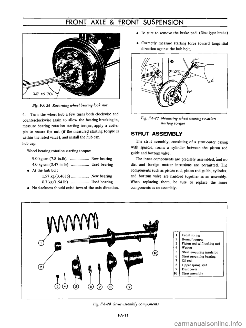
4
Turn
the
wheel
hub
a
few
turns
both
clockwise
and
counterclockwise
again
to
allow
the
bearing
breaking
in
measure
bearing
rotation
starting
torque
apply
a
cotter
pin
to
secure
the
nut
if
the
measured
starting
torque
is
within
the
rated
value
and
install
the
hub
cap
hub
cap
Wheel
bearing
rotation
starting
torque
9
0
kg
cm
7
8
in
1b
4
0
kg
cm
3
4
7
in
1b
At
the
hub
bolt
1
57
kg
3
461b
New
bearing
0
7
kg
1
54lb
Used
bearing
No
slackness
should
exist
toward
the
axis
direction
New
bearing
Used
bearing
J
o
i
@
j
Be
sure
to
remove
the
brake
pad
Disc
type
brake
Correctly
measure
starting
force
toward
tangential
direction
against
the
hub
bolt
Fig
FA
27
Measuring
wheel
bearing
ro
ation
starting
torque
STRUT
ASSEMBLY
The
strut
assembly
consisting
of
a
strut
outer
casing
with
spindle
forms
a
cylinder
between
the
piston
rod
guide
and
bottom
valve
The
inner
components
are
precisely
assembled
and
no
dirt
and
foreign
matter
intrusions
are
permitted
The
components
such
as
piston
rod
piston
rod
guide
cylinder
and
bottom
valve
are
handled
together
as
an
assembly
When
replacing
them
be
sure
to
replace
the
inner
components
as
an
assembly
1
2
3
4
5
6
7
8
9
10
Front
spring
Bound
bumper
Piston
rod
self
locking
nut
Washer
Strut
mounting
insulator
Strut
mounting
bearing
Oil
seal
Upper
spring
seat
Dust
cover
Strut
assembly
Fig
FA
28
Strut
assembly
components
FA
l1
Page 110 of 513

CHASSIS
Strut
assembly
Strut
outer
diameter
Piston
rod
diameter
mmlin
nml
in
45
17
7
18
0
709
15
0
984
Piston
diameter
mmlin
Damping
force
at
piston
speed
0
3
m
sec
Expansion
kg
Ib
Compression
kg
lb
48
106
22
48
5
Piston
rod
Bend
limit
Wear
limit
mm
in
0
1
0
0039
mm
in
0
025
0
0010
Piston
cylinder
Bend
limit
Wear
limit
inside
mm
in
mm
in
0
2
0
0079
0
1
0
0039
17
0
669
Stabilizer
bar
diameter
mm
in
Front
wheel
bearing
rotation
starting
torque
kg
cm
in
lb
Ball
joint
shaking
torque
kg
cm
in
lb
Ball
joint
end
play
axial
direction
mm
in
9
0
7
8
35
to
60
30
4
to
52
1
0
3
to
1
0
0
0118
to
0
0394
TIGHTENING
TORQUE
Front
axle
Brake
disc
rotor
and
hub
assembly
tightening
torque
Wheel
bearing
lock
nut
Disc
brake
caliper
fixing
bolt
Buffle
plate
installation
screw
Brake
disc
assembly
installation
bolt
kg
m
ft
lb
4
4
to
5
9
31
8
to
42
7
2
2
to
2
4
15
9
to
174
4
6
to
6
1
33
3
to
44
1
0
3
to
0
4
2
1
to
2
9
2
7
to
3
7
19
5
to
26
8
Strut
assembly
Gland
packing
tightening
torque
Piston
rod
self
locking
nut
Upper
support
nut
8
0
to
11
0
57
8
to
79
5
3
6
to
4
5
26
0
to
32
5
1
6
to
2
1
I
1
6
to
15
2
Transverse
link
and
ball
joint
Bolts
used
to
install
the
knuckle
arm
to
strut
Ball
joint
castle
nut
Bolts
used
to
install
the
transverse
link
to
ball
4
6
to
6
1
33
3
to
44
1
5
5
to
7
4
39
8
to
53
5
FA
24
Page 122 of 513
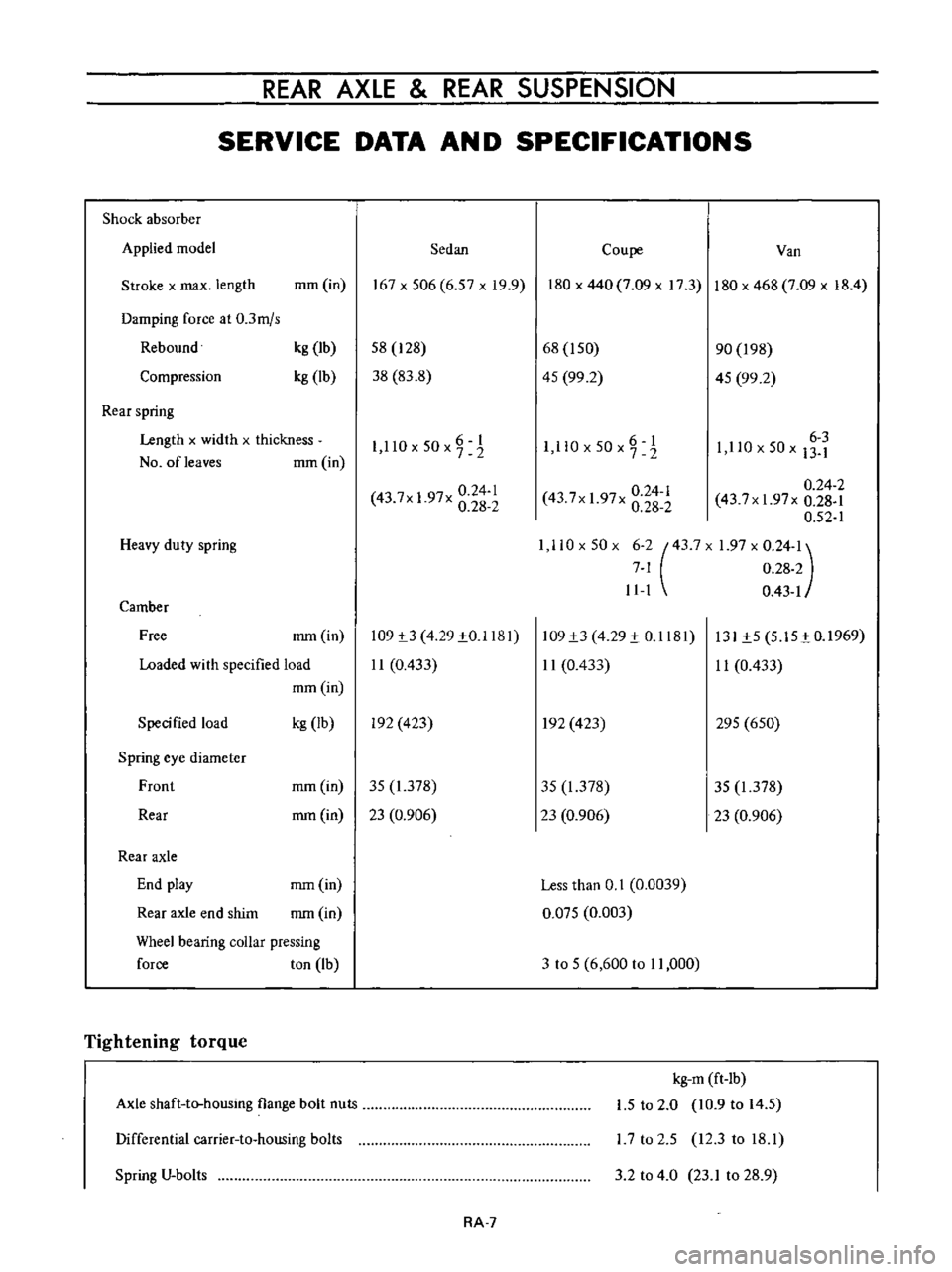
REAR
AXLE
REAR
SUSPENSION
SERVICE
DATA
AN
D
SPECIFICATIONS
Shock
absorber
Applied
model
Sedan
Coupe
Van
Stroke
x
max
length
mm
in
167x506
6
57xI9
9
180
x
440
7
09
x
17
3
180
x
468
7
09
x
18
4
Damping
force
at
0
3mjs
Rebound
Compression
kg
Ib
kg
lb
58
128
38
83
8
68
I
50
45
99
2
90
198
45
99
2
Rear
spring
Length
x
widlh
x
thickness
NO
ofleaves
mm
in
6
I
1
llOx50x72
O
6
1
I
ll
x50x7
2
6
3
1
110
x
50
x
13
1
0
24
1
43
7x
1
97x
0
28
2
0
24
2
43
7xI
97x
0
28
1
0
52
1
1
110x50x
6
2
43
7X
1
97
x
0
24
1
7
1
0
28
2
11
1
0
43
1
0
24
1
43
7x
1
97x
0
28
2
Heavy
duty
spring
Camber
Free
mm
in
109
t3
4
29
1
0
1181
11
0
433
109
1
3
4
29
1
0
1181
11
0
433
131
1
5
5
15
tO
1969
11
0
433
Loaded
wi
th
specified
load
mm
in
Specified
load
kg
Ib
In
423
In
423
295
650
Spring
eye
diameter
Front
mm
in
35
1
378
35
1
378
35
1
378
Rear
mm
in
23
0
906
23
0
906
23
0
906
Rear
axle
End
play
mm
in
Less
than
0
1
0
0039
Rear
axle
end
shim
mm
in
0
Q75
0
003
Wheel
bearing
coUar
pressing
force
ton
Ib
3
to
5
6
600
to
11
000
Tightening
torque
Axle
shaft
to
housing
flange
bolt
nuts
kg
m
ft
lb
1
5
to
2
0
10
9
to
14
5
L7
to
2
5
12
3
to
18
1
Differential
carrier
to
housing
bolts
Spring
V
bolts
3
2
to
4
0
23
1
to
28
9
RA
7