1973 DATSUN B110 water pump
[x] Cancel search: water pumpPage 54 of 513

through
all
drive
positions
and
place
the
lever
in
park
P
position
In
this
inspection
the
car
must
be
placed
on
a
level
surface
The
amount
of
the
oil
varies
with
the
temperature
As
a
rule
the
oil
level
must
be
measured
after
its
tempera
ture
becomes
sufficiently
high
I
Fill
the
oil
to
the
line
H
The
difference
of
capacities
between
both
H
and
L
is
approximately
0
4
liter
7
8
U
S
pt
3
4
Imper
pt
and
therefore
take
care
not
to
fill
beyond
the
line
H
2
At
the
time
of
the
above
topping
up
and
changing
of
oil
care
should
be
taken
of
to
prevent
mixing
the
oil
with
dust
and
water
2
Inspecting
oil
condition
The
condition
of
oil
sticking
to
the
level
gauge
indicates
whether
to
over
haul
and
repair
the
transmission
or
look
for
the
defective
part
If
the
oil
has
deteriorated
into
a
varnish
like
quality
it
causes
the
con
trol
valve
to
stick
The
blackened
oil
gives
the
proof
of
the
burned
clutch
brake
band
etc
In
these
cases
the
transmission
must
be
replaced
Notes
a
In
oil
level
checking
use
special
paper
waste
to
handle
the
level
gauge
and
take
care
not
to
let
the
scraps
of
paper
and
cloth
tick
to
the
gauge
b
Insert
the
gauge
fully
and
take
it
out
quickly
before
splashing
oil
adheres
to
the
gauge
and
theu
observe
the
level
c
Use
automatic
transmission
fluid
having
DEXRON
iden
tIficatIon
only
in
the
3N71
B
automatic
transmission
d
Pay
atteutIon
because
the
oil
to
be
used
dIffers
from
that
i
used
in
the
Nissan
Full
Automatic
Transmission
3N7IA
Never
mix
the
oil
with
that
CHASSIS
Inspection
and
repair
of
oil
leakage
When
oil
leakage
takes
place
the
portion
near
the
leakage
is
covered
with
oil
presenting
difficulty
in
de
tecting
the
spot
Therefore
the
places
where
oil
seals
and
gaskets
are
equipped
are
enumerated
below
I
Converter
housing
The
rubber
ring
of
oil
pump
hous
ing
The
oil
eaI
of
oil
pump
housing
The
oil
seal
of
engine
crankshaft
The
bolts
of
converter
housing
to
case
2
Transmission
and
rear
extension
Junction
of
transmission
and
rear
extension
Oil
tube
connectors
Oil
pan
Oil
pressure
inspection
holes
Refer
to
Figure
AT
112
The
mounting
portion
of
vacuum
diaphragm
and
downshift
solenoid
Breather
and
oil
charging
pipe
Speedometer
pinion
sleeve
The
oil
seal
of
rear
extension
To
exactly
locate
the
place
of
oil
leakage
proceeds
as
follows
Place
the
vehicle
in
a
pit
and
by
sampling
the
leaked
oil
examine
whe
ther
it
is
the
torq
le
converter
oil
or
not
The
torque
converter
oil
assumes
color
like
red
wine
when
shipped
from
the
factory
so
it
is
ea
ily
distin
guished
from
engine
oil
or
gear
oil
Cleanly
wipe
off
the
leaking
oil
and
dust
and
detect
the
spot
of
oil
leakage
Use
nonflammable
organic
solvent
such
as
carbon
tetrachloride
for
wip
ing
Raise
the
oil
temperature
by
op
erating
the
engine
and
shift
the
lever
to
0
to
heighten
the
oil
pressure
The
spot
of
oil
leakage
will
then
be
found
more
easily
Note
A
the
oil
leakage
from
the
breather
does
not
take
place
except
when
running
at
high
speed
it
is
impossible
to
locate
the
spot
of
leakage
with
vehicle
stalled
AT
50
Checking
engine
idling
rprn
The
engine
idling
revolution
should
be
properly
adjusted
If
the
engine
revolution
is
too
low
the
engine
does
not
operate
smoothly
and
if
too
high
a
strong
shock
or
creep
develops
when
changing
over
from
N
to
D
or
R
Specified
idling
speed
650
rpm
at
D
position
800
rpm
at
N
position
Checking
and
adjusting
kick
down
switch
and
downshift
solenoid
When
the
kick
down
operation
is
not
made
properly
or
the
speed
chang
ing
point
is
too
high
check
the
kick
down
switch
downshift
solenoid
and
wiring
between
them
When
the
igni
tion
key
is
positioned
at
the
1st
stage
and
the
accelerator
pedal
is
depressed
deeply
the
switch
contact
should
be
closed
and
the
solenoid
should
click
If
it
does
not
click
it
indicates
a
defect
Then
check
each
part
with
the
testing
instruments
See
Figure
AT
I09
0
0
1
M
r
7
I
Y
ATl08
Fig
A
T
l
09
Downshift
solenoid
Note
Watch
for
oil
leakage
from
transmission
case
Page 270 of 513
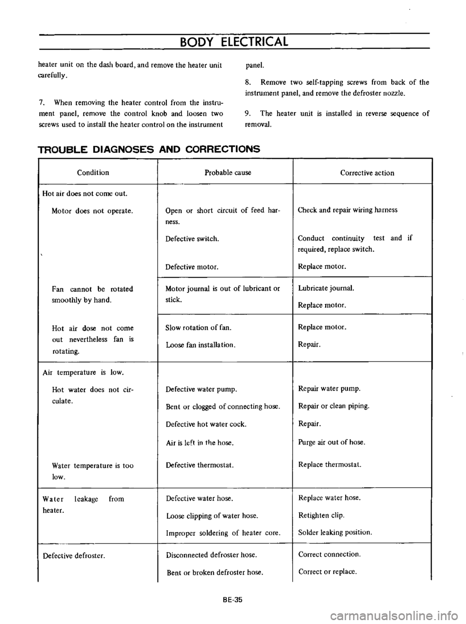
BODY
ELECTRICAL
heater
unit
on
the
dash
board
and
remove
the
heater
unit
carefully
panel
8
Rernove
two
self
tapping
screws
from
back
of
the
instrument
panel
and
remove
the
defroster
nozzle
7
When
removing
the
heater
control
from
the
instru
ment
panel
remove
the
control
knob
and
loosen
two
screws
used
to
install
the
heater
control
on
the
instrument
9
The
heater
unit
is
installed
in
reverse
sequence
of
removal
TROUBLE
DIAGNOSES
AND
CORRECTIONS
Condition
Probable
cause
Hot
air
does
not
come
out
Motor
does
not
operate
Open
or
short
circuit
of
feed
har
ness
Defective
switch
Defective
motor
Fan
cannot
be
rotated
smoothly
by
hand
Motor
journal
is
out
of
lubricant
or
stick
Hot
air
dose
not
come
out
nevertheless
fan
is
rotating
Slow
rotation
of
fan
Loose
fan
installation
Air
temperature
is
low
Hot
water
does
not
cir
culate
Defective
water
pump
Bent
or
clogged
of
connecting
hose
Defective
hot
water
cock
Air
is
left
in
the
hose
Water
temperature
is
too
low
Defective
thermostat
Water
leakage
from
heater
Defective
water
hose
Loose
clipping
of
water
hose
Improper
soldering
of
heater
core
Defective
defroster
Disconnected
defroster
hose
Bent
or
broken
defroster
hose
BE
35
Corrective
action
Check
and
repair
wiring
harness
Conduct
continuity
test
and
if
required
replace
switch
Replace
motor
Lubricate
journal
Replace
motor
Replace
motor
Repair
Repair
water
pump
Repair
or
clean
piping
Repair
Purge
air
out
of
hose
Replace
thermostat
Replace
water
hose
Retighten
clip
Solder
leaking
position
Correct
connection
Correct
or
replace
Page 335 of 513
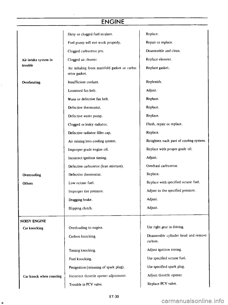
Air
intake
system
in
trouble
Overheating
Overcooling
Others
NOISY
ENGINE
Car
knocking
Car
knock
when
coasting
ENGINE
Diny
ur
clogged
fuel
strainer
Fuel
pump
will
not
work
properly
Clogged
carburetor
jets
Clogged
air
cleaner
Air
inhaling
from
manifold
gasket
or
carbu
retor
gasket
Insufficient
coolant
Loosened
fan
belt
Worn
or
defective
fan
belt
Defective
thermostat
Defective
water
pump
Clogged
or
leaky
radiator
Defective
radiator
filler
cap
Air
mixing
into
cooling
system
Improper
grade
engine
oil
Incorrect
ignition
timing
Defective
carburetor
lean
mixture
Defective
thermostat
Low
octane
fuel
Improper
tire
pressure
Dragging
brake
Slipping
clutch
Overloading
to
engine
Carbon
knocking
Timing
knocking
Fuel
knocking
Preignition
misusing
of
spark
plug
Incorrect
throttle
opener
adjustment
Trouble
in
PCV
valve
ET
30
Replace
Repair
or
replace
Disassemble
and
clean
Replace
element
Replace
gasket
Replenish
Adjust
Replace
Replace
Replace
Flush
repair
or
replace
Replace
Retighten
each
part
of
cooling
system
Replace
with
proper
grade
oil
Adjust
Overhaul
carburetor
Replace
Replace
with
specified
octane
fuel
Adjust
to
the
specified
pressure
Adjust
Adjust
Use
right
gear
in
driving
Disassemble
cylinder
head
and
remove
carbon
Adjust
ignition
timing
Use
specified
octane
fuel
Use
specified
spark
plug
Adjust
throttle
opener
Replace
PCV
valve
Page 336 of 513
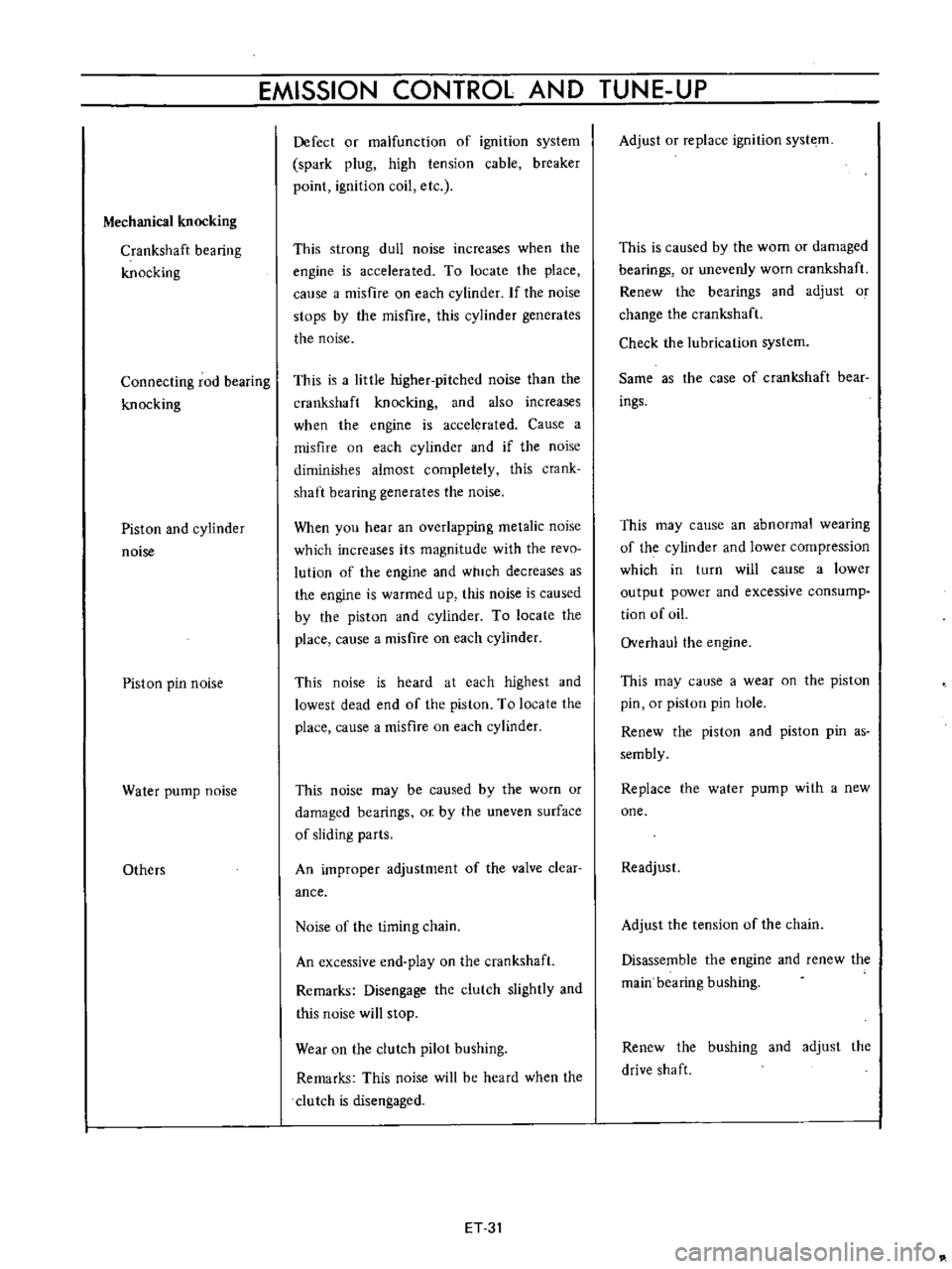
EMISSION
CONTROL
AND
TUNE
UP
Mechanical
knocking
Crankshaft
bearing
knocking
Connecting
rod
bearing
knocking
Piston
and
cylinder
noise
Piston
pin
noise
Water
pump
noise
Others
Defect
or
malfunction
of
ignition
system
spark
plug
high
tension
cable
breaker
point
ignition
coil
etc
This
strong
dull
noise
increases
when
the
engine
is
accelerated
To
locate
the
place
calise
a
misfire
on
each
cylinder
If
the
noise
stops
by
the
misfire
this
cylinder
generates
the
noise
This
is
a
little
higher
pitched
noise
than
the
crankshaft
knocking
and
also
increases
when
the
engine
is
accelerated
Cause
a
misfire
on
each
cylinder
and
if
the
noise
diminishes
almost
completely
this
crank
shaft
bearing
generates
the
noise
When
you
hear
an
overlapping
metalic
noise
which
increases
its
magnitude
with
the
revo
lution
of
the
engine
and
which
decreases
as
the
engine
is
warmed
up
this
noise
is
caused
by
the
piston
and
cylinder
To
locate
the
place
cause
a
misfire
on
each
cylinder
This
noise
is
heard
at
each
highest
and
lowest
dead
end
of
the
piston
To
locate
the
place
cause
a
misfire
on
each
cylinder
This
noise
may
be
caused
by
the
worn
or
damaged
bearings
or
by
the
uneven
surface
of
sliding
parts
An
improper
adjustment
of
the
valve
clear
ance
Noise
of
the
timing
chain
An
excessive
end
play
on
the
crankshaft
Remarks
Disengage
the
clutch
slightly
and
this
noise
will
stop
Wear
on
the
clutch
pilot
bushing
Remarks
This
noise
will
be
heard
when
the
clutch
is
disengaged
ET
31
Adjust
or
replace
ignition
syste
m
This
is
caused
by
the
wom
or
damaged
bearings
or
unevenly
worn
crankshaft
Renew
the
bearings
and
adjust
o
change
the
crankshaft
Check
the
lubrication
system
Same
as
the
case
of
crankshaft
bear
ings
This
may
cause
an
abnormal
wearing
of
the
cylinder
and
lower
compression
which
in
turn
will
cause
a
lower
output
power
and
excessive
consump
tion
of
oiL
Overhaul
the
engine
This
may
cause
a
wear
on
the
piston
pin
or
piston
pin
hole
Renew
the
piston
and
piston
pin
as
sembly
Replace
the
water
pump
with
a
new
one
Readjust
Adjust
the
tension
of
the
chain
Disassemble
the
engine
and
renew
the
main
bearing
bushing
Renew
the
bushing
and
adjust
the
drive
shaft
Page 345 of 513
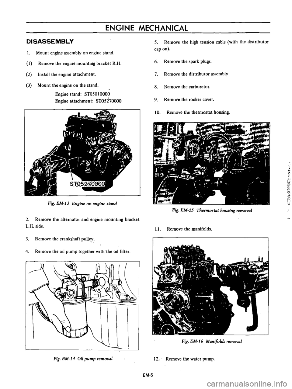
ENGINE
MECHANICAL
I
I
J
I
v
Fig
EM
13
Engine
on
engine
stand
DISASSEMBLY
1
Mount
engine
assembly
on
engine
stand
I
Remove
the
engine
mounting
bracket
R
H
2
Install
the
engine
attachment
3
Mount
the
engine
on
the
stand
Engine
stand
ST050
10000
Engine
attachment
ST05270000
2
Remove
the
alternator
and
engine
mounting
bracket
L
H
side
3
Remove
the
crankshaft
pulley
4
Remove
the
oil
pump
together
with
the
oil
ftIter
Fig
EM
14
Oil
pump
removal
5
Remove
the
high
tension
cable
with
the
distributor
cap
on
6
Remove
the
spark
plugs
7
Remove
the
distributor
assembly
8
Remove
the
carburetor
9
Remove
the
rocker
cover
10
Remove
the
thermostat
housing
Fig
EM
15
Thermostat
housing
removal
I
L
Remove
the
manifolds
Fig
EM
16
Manifolds
removal
12
Remove
the
water
pump
EM
5
Page 346 of 513
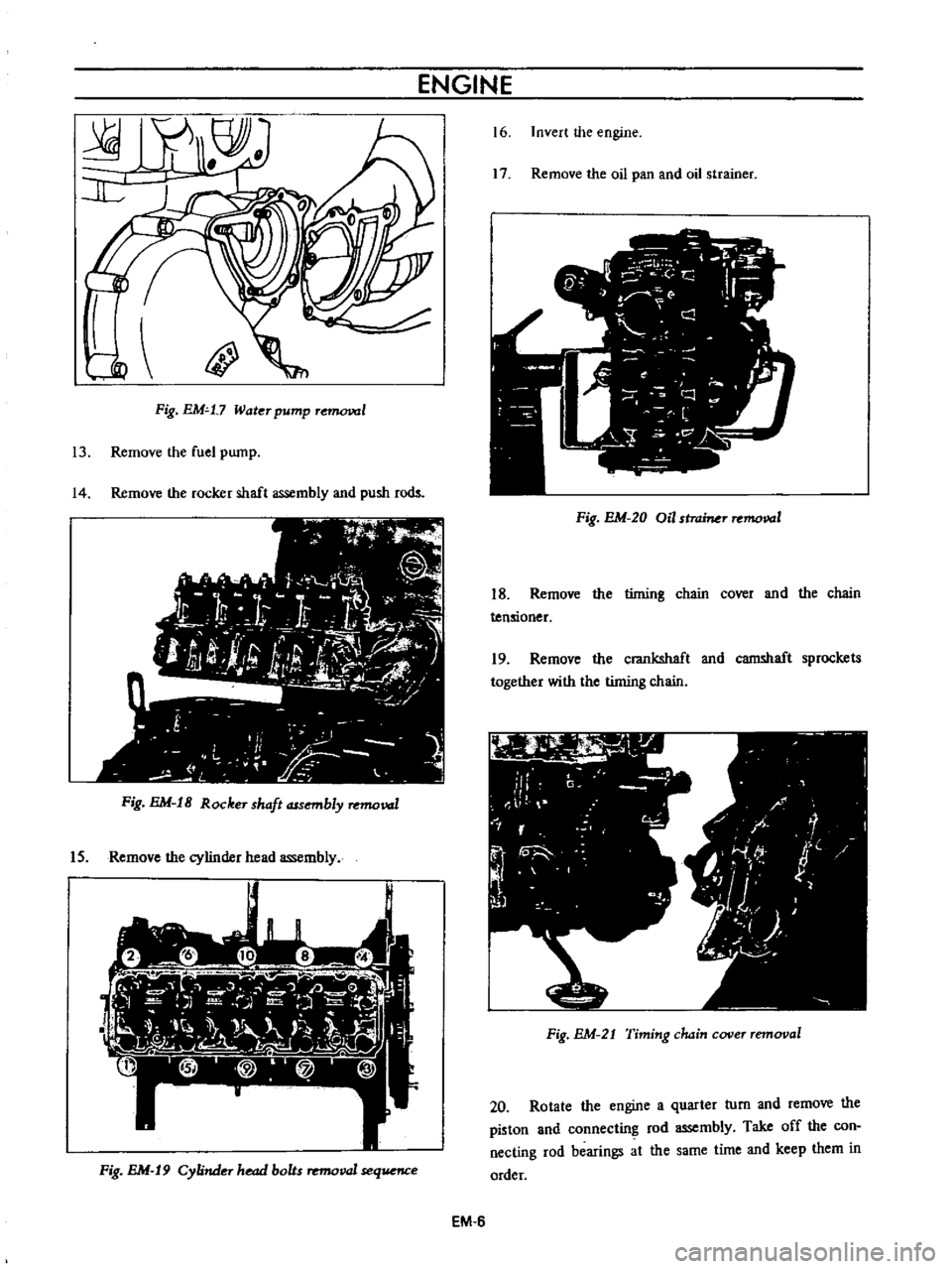
ENGINE
l
JJ
l
Ii
Fig
EM
t7
Water
pump
r
1
13
Remove
the
fuel
pump
14
Remove
the
rocker
shaft
assembly
and
push
rods
Fig
EM
18
Rocker
shaft
assembly
removal
IS
Remove
the
cylinder
head
assembly
Fig
EM
19
Cylinder
head
bolts
removal
sequence
16
Invert
the
engine
17
Remove
the
oil
pan
and
oil
strainer
Fig
EM
20
Oil
stromer
removal
18
Remove
the
timing
chain
cover
and
the
chain
tensioner
19
Remove
the
crankshaft
and
camshaft
sprockets
together
with
the
timing
chain
Fig
EM
21
Timing
chain
cover
removal
20
Rotate
the
engine
a
quarter
turn
and
remove
the
piston
and
connecting
rod
assembly
Take
off
the
con
necting
rod
bearings
at
the
same
time
and
keep
them
in
order
EM
6
Page 371 of 513
ENGINE
MECHANICAL
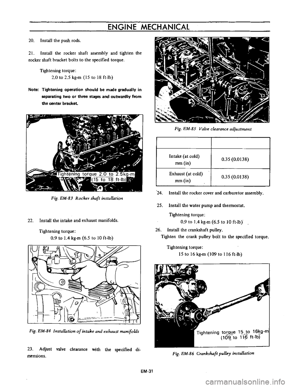
20
Install
the
push
rods
21
Install
the
rocker
shaft
assembly
and
tighten
the
rocker
shaft
bracket
bolts
to
the
specified
torque
Tightening
torque
2
0
to
2
5
kg
m
15
to
18
ft
Ib
Note
Tightening
operation
should
be
made
gradually
in
separating
two
or
three
stages
and
outwardly
from
the
center
bracket
Fig
EM
B
RockeT
shaft
installation
22
Install
the
intake
and
exhaust
manifolds
Tightening
torque
0
9
to
I
4
kg
m
6
5
to
10
ft
lb
Fig
EM
B4
Installation
of
intake
and
exhaust
manifolds
23
Adjust
valve
clearance
with
the
specified
di
mensions
Fig
EM
85
Valve
clearance
adjustment
Intake
at
cold
rom
in
0
35
0
0138
Exhaust
at
cold
rom
in
0
35
0
0138
24
Install
the
rocker
cover
and
carburetor
assembly
25
Install
the
water
pump
and
thermostat
Tightening
torque
0
9
to
I
4
kg
m
6
5
to
10
ft
lb
26
Install
the
crankshaft
pulley
Tighten
the
crank
pulley
bolt
to
the
specified
torque
Tightening
torque
15
to
16
kg
m
109
to
116
ft
lb
Tightening
tOI
q
e
15
JP
16
g
m
10l
to
11
ft
Ib
Fig
EM
B6
CTankshaft
pulky
installation
EM
31
Page 379 of 513
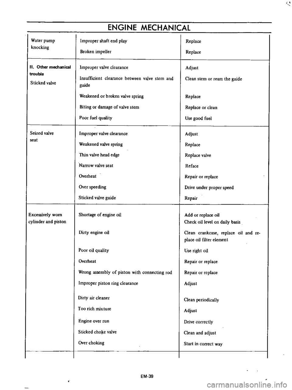
Water
pump
knocking
II
Other
mechanical
trouble
Sticked
valve
Seized
valve
seat
Excessively
worn
cylinder
and
piston
ENGINE
MECHANICAL
Improper
shaft
end
play
Broken
impeller
Improper
valve
clearance
Insufficient
clearance
between
valve
stem
and
guide
Weakened
or
broken
valve
spring
Biting
or
damage
ofvalve
stem
Poor
fuel
quality
Improper
valve
clearance
Weakened
valve
spring
Thin
valve
head
edge
Narrow
valve
seat
Overheat
Over
speeding
Sticked
valve
guide
Shortage
of
engine
oil
Dirty
engine
oil
Poor
oil
quality
Overheat
Wrong
assembly
of
piston
with
connecting
rod
Improper
piston
ring
clearance
Dirty
air
cleaner
Too
rich
mixture
Engine
over
run
Slicked
cho
e
valve
Over
choking
EM
39
Replace
Replace
Adjust
Clean
stem
or
ream
the
guide
Replace
Replace
or
clean
Use
good
fuel
Adjust
Replace
Replace
valve
Reface
Repair
or
replace
Drive
under
proper
speed
Repair
Add
or
replace
oil
Check
oil
level
on
daily
basis
Clean
crankcase
replace
oil
and
re
place
oil
fIlter
element
use
right
oil
Repair
or
replace
Repair
or
replace
Adjust
Clean
periodically
Adjust
Drive
correctly
Clean
and
adjust
Start
in
correct
way