1973 DATSUN B110 air condition
[x] Cancel search: air conditionPage 48 of 513
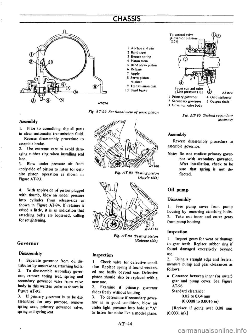
Assembly
I
Prior
10
assemlbing
dip
all
parts
in
clean
automatic
transmission
fluid
Reverse
disassembly
procedure
to
assemble
brake
2
Use
extreme
care
to
avoid
dam
aging
rubber
ring
when
installing
seal
lace
3
Blow
under
pressure
air
from
apply
side
of
piston
to
lislen
for
defi
nite
piston
operation
as
shown
in
Figure
AT
93
4
With
appIy
side
of
piston
plugged
with
thumb
blow
air
under
pressure
into
cylinder
from
release
side
as
shown
in
Figure
AT
94
If
retainer
is
raised
a
little
it
is
an
indication
that
attaching
bolts
are
loosened
calling
for
retightening
Governor
Disassembly
l
Separate
governor
from
oil
dis
tributor
by
unscrewing
attaching
bolts
2
To
disassemble
secondary
gover
nor
remove
spring
seat
spring
and
secondary
governor
valve
from
valve
body
in
this
written
order
as
shown
in
Figure
AT
95
3
If
primary
governor
is
to
be
dis
assembled
for
any
purpose
remove
spring
seat
primary
governor
valve
spring
and
spring
eal
CHASSIS
I
Anchor
end
pin
2
Band
strut
3
Return
spring
4
Piston
stem
5
Band
servo
piston
6
Release
7
Apply
8
Servo
piston
relainer
9
Transmission
case
10
Band
brake
AT074
Fig
A
T
92
Sectional
view
of
servo
piston
Fig
A
T
93
Testing
piston
Apply
side
Fig
A
T
94
Testing
pi8ton
Rele
side
Inspection
I
Check
valve
for
defective
condi
tion
Replace
spring
if
found
weaken
ed
too
badly
beyond
use
Defective
piston
should
also
be
replaced
with
a
new
one
2
Examine
if
primary
governor
slides
freely
without
binding
3
To
determine
if
secondary
gover
nor
is
in
good
condition
blow
air
under
light
pressure
into
hole
at
A
to
listen
for
noise
like
a
model
plane
AT
44
r
To
control
valve
Governor
pressure
15
1
4
From
control
valve
Line
pressure
I
I
Primary
governor
2
Secondary
governor
3
Governor
valve
body
A
TogO
4
Oil
distributor
5
Output
shaft
Fig
A
T
95
Testing
secondary
governor
Assembly
Reverse
disassembly
procedure
to
assemble
governor
Note
Do
nol
confuse
primary
gover
nor
wilh
secondary
governor
After
instaDation
check
to
be
sure
that
spring
is
nol
de
flecled
Oil
pump
Disassembly
I
Free
pump
cover
from
pump
housing
by
removing
attaching
bolts
2
Take
out
inner
and
outer
gears
from
pump
houisng
Inspection
1
Inspect
gears
for
wear
or
damage
to
gear
leeth
Replace
rubber
ring
if
found
damaged
excessively
beyond
use
2
Using
a
straight
edge
and
feelers
measure
pump
and
gear
clearances
as
follows
Clearance
between
inner
or
outer
gear
and
pump
cover
See
Figure
AT
96
Standard
clearance
0
02
to
0
04
mm
0
0008
to
0
0016
in
Replace
if
going
over
0
08
mm
0
0031
in
Page 53 of 513

AUTOMATIC
TRANSMISSIO
N
TROUBLE
DIAGNOSES
AND
ADJUSTMENT
INSPECTION
AND
ADJUSTMENT
BEFORE
TROUBLE
DIAGNOSIS
Testing
instrument
for
inspection
Checking
oil
level
Inspection
and
repair
of
oil
leakage
Checking
engine
idling
rpm
Checking
and
adjusting
kick
down
switch
and
downshift
solenoid
Inspection
and
adjustment
of
manual
linkage
Checking
and
adjusting
inhibitor
switch
STALL
TEST
Stall
test
procedures
Judgement
As
the
troubles
on
the
automatic
transmission
can
be
mostly
repaired
by
doing
simple
adjustment
so
do
not
disassemble
immediately
if
the
auto
m
tic
transmission
is
in
trouble
Firstly
inspect
and
adjust
the
auto
matic
transmission
with
mounting
on
vehicle
by
observing
the
trouble
shooting
chart
If
the
trouble
could
not
be
solved
by
this
procedure
then
remove
and
disassemble
the
automatic
transmis
sion
It
is
advisable
to
check
overhaul
and
repair
each
point
in
the
order
itemized
in
the
trouble
shooting
chart
l
In
the
trouble
shooting
chart
the
diagnosis
items
are
arranged
in
the
order
from
easy
to
difficult
and
there
fore
please
follow
these
items
The
transmission
should
not
be
removed
unless
necessary
2
The
test
and
adjustment
for
trou
ble
diagnosis
should
be
made
on
the
basis
of
standard
values
and
the
data
should
be
recorded
ROAD
TEST
Car
speed
at
gear
shift
Checking
speed
changing
condition
Checking
items
during
speed
change
Shift
schedule
LINE
PRESSURE
TEST
Line
pressure
governor
feed
pressure
Judgement
in
measuring
line
pressure
TROUBLE
SHOOTING
CHART
Inspecting
items
Trouble
shooting
chart
for
3N71
B
Automatic
Transmission
Trouble
shooting
guide
for
3N718
Automatic
Transmission
CONTENTS
AT
49
AT
49
AT
49
AT
50
AT
50
AT
50
AT
51
AT
51
AT
51
AT51
AT
52
INSPECTION
AND
AD
JUSTMENT
BEFORE
TROUBLE
DIAGNOSIS
Testing
instrument
for
inspection
1
Engine
tachometer
2
Vacuum
gauge
3
Oil
pressure
gauge
It
is
convenient
to
install
these
instruments
in
a
way
that
allows
meas
urements
to
be
made
from
the
driver
s
seat
Checking
oil
level
In
checking
the
automatic
transmis
sion
the
oil
level
and
the
condition
of
oil
around
the
oil
level
gauge
should
be
examined
every
5
000
km
3
000
miles
These
steps
are
easy
and
effec
live
in
trouble
shooting
as
some
change
of
oil
conditions
are
linked
with
developed
troubles
in
many
cases
AT
49
AT
52
AT
52
AT
53
AT
53
AT
53
AT
53
AT
53
AT
54
AT
54
AT
54
AT
55
AT
5B
For
instance
Lack
of
oil
causes
defective
opera
tion
by
making
the
clutches
and
brakes
slip
developing
severe
wear
The
cause
of
this
operation
is
that
the
oil
pump
has
begun
to
suck
air
which
caused
oil
foaming
thus
rapidly
deteriora
ting
the
oil
quality
and
pro
ducing
sludge
and
varnish
Meanwhile
excessive
oil
is
also
bad
as
in
the
case
of
a
lack
of
oil
because
of
oil
foaming
by
being
stirred
up
by
the
gears
Moreover
in
high
speed
driving
with
excessive
oil
in
the
trans
mission
the
oil
often
blows
out
from
the
breather
I
Measuring
oil
level
When
checking
the
fluid
level
start
the
engine
and
run
it
until
normal
operating
temperatures
oil
tempera
ture
50
to
800e
122
to
176
F
Approximately
ten
minute
operation
will
elevate
the
temperature
to
this
range
and
enigne
idling
conditions
are
stabilized
Then
apply
the
brakes
and
move
the
transmission
shift
lever
Page 54 of 513

through
all
drive
positions
and
place
the
lever
in
park
P
position
In
this
inspection
the
car
must
be
placed
on
a
level
surface
The
amount
of
the
oil
varies
with
the
temperature
As
a
rule
the
oil
level
must
be
measured
after
its
tempera
ture
becomes
sufficiently
high
I
Fill
the
oil
to
the
line
H
The
difference
of
capacities
between
both
H
and
L
is
approximately
0
4
liter
7
8
U
S
pt
3
4
Imper
pt
and
therefore
take
care
not
to
fill
beyond
the
line
H
2
At
the
time
of
the
above
topping
up
and
changing
of
oil
care
should
be
taken
of
to
prevent
mixing
the
oil
with
dust
and
water
2
Inspecting
oil
condition
The
condition
of
oil
sticking
to
the
level
gauge
indicates
whether
to
over
haul
and
repair
the
transmission
or
look
for
the
defective
part
If
the
oil
has
deteriorated
into
a
varnish
like
quality
it
causes
the
con
trol
valve
to
stick
The
blackened
oil
gives
the
proof
of
the
burned
clutch
brake
band
etc
In
these
cases
the
transmission
must
be
replaced
Notes
a
In
oil
level
checking
use
special
paper
waste
to
handle
the
level
gauge
and
take
care
not
to
let
the
scraps
of
paper
and
cloth
tick
to
the
gauge
b
Insert
the
gauge
fully
and
take
it
out
quickly
before
splashing
oil
adheres
to
the
gauge
and
theu
observe
the
level
c
Use
automatic
transmission
fluid
having
DEXRON
iden
tIficatIon
only
in
the
3N71
B
automatic
transmission
d
Pay
atteutIon
because
the
oil
to
be
used
dIffers
from
that
i
used
in
the
Nissan
Full
Automatic
Transmission
3N7IA
Never
mix
the
oil
with
that
CHASSIS
Inspection
and
repair
of
oil
leakage
When
oil
leakage
takes
place
the
portion
near
the
leakage
is
covered
with
oil
presenting
difficulty
in
de
tecting
the
spot
Therefore
the
places
where
oil
seals
and
gaskets
are
equipped
are
enumerated
below
I
Converter
housing
The
rubber
ring
of
oil
pump
hous
ing
The
oil
eaI
of
oil
pump
housing
The
oil
seal
of
engine
crankshaft
The
bolts
of
converter
housing
to
case
2
Transmission
and
rear
extension
Junction
of
transmission
and
rear
extension
Oil
tube
connectors
Oil
pan
Oil
pressure
inspection
holes
Refer
to
Figure
AT
112
The
mounting
portion
of
vacuum
diaphragm
and
downshift
solenoid
Breather
and
oil
charging
pipe
Speedometer
pinion
sleeve
The
oil
seal
of
rear
extension
To
exactly
locate
the
place
of
oil
leakage
proceeds
as
follows
Place
the
vehicle
in
a
pit
and
by
sampling
the
leaked
oil
examine
whe
ther
it
is
the
torq
le
converter
oil
or
not
The
torque
converter
oil
assumes
color
like
red
wine
when
shipped
from
the
factory
so
it
is
ea
ily
distin
guished
from
engine
oil
or
gear
oil
Cleanly
wipe
off
the
leaking
oil
and
dust
and
detect
the
spot
of
oil
leakage
Use
nonflammable
organic
solvent
such
as
carbon
tetrachloride
for
wip
ing
Raise
the
oil
temperature
by
op
erating
the
engine
and
shift
the
lever
to
0
to
heighten
the
oil
pressure
The
spot
of
oil
leakage
will
then
be
found
more
easily
Note
A
the
oil
leakage
from
the
breather
does
not
take
place
except
when
running
at
high
speed
it
is
impossible
to
locate
the
spot
of
leakage
with
vehicle
stalled
AT
50
Checking
engine
idling
rprn
The
engine
idling
revolution
should
be
properly
adjusted
If
the
engine
revolution
is
too
low
the
engine
does
not
operate
smoothly
and
if
too
high
a
strong
shock
or
creep
develops
when
changing
over
from
N
to
D
or
R
Specified
idling
speed
650
rpm
at
D
position
800
rpm
at
N
position
Checking
and
adjusting
kick
down
switch
and
downshift
solenoid
When
the
kick
down
operation
is
not
made
properly
or
the
speed
chang
ing
point
is
too
high
check
the
kick
down
switch
downshift
solenoid
and
wiring
between
them
When
the
igni
tion
key
is
positioned
at
the
1st
stage
and
the
accelerator
pedal
is
depressed
deeply
the
switch
contact
should
be
closed
and
the
solenoid
should
click
If
it
does
not
click
it
indicates
a
defect
Then
check
each
part
with
the
testing
instruments
See
Figure
AT
I09
0
0
1
M
r
7
I
Y
ATl08
Fig
A
T
l
09
Downshift
solenoid
Note
Watch
for
oil
leakage
from
transmission
case
Page 55 of 513

c
Inspection
and
adJu
Stmenf
trouble
first
check
the
linhge
f
no
1
i
jI
fect
is
found
in
the
lin1
age
check
of
manu
a
l
liiiJ
i
the
inhibitor
switch
Th
d
1F
aI
S
t
th
I
I
f
e
a
JU
i
J
u
epara
e
e
range
se
eet
ever
rom
Iy
important
ii
s3
ns
etion
of
oil
the
lower
shift
rod
and
turn
the
range
1
level
for
the
automatiC
tran
smission
select
lever
to
N
Therefore
great
care
should
be
exer
Note
In
the
position
N
the
slot
of
cised
because
defective
adjustment
will
the
manual
shaft
is
vertical
result
in
the
breakdown
of
the
trans
By
the
use
of
the
tester
check
the
two
bIack
yellow
BY
wires
from
the
inhibitor
switch
in
the
ranges
N
and
P
and
the
two
red
bIack
RB
wires
in
the
range
R
for
continuity
Turn
range
select
lever
to
both
directions
from
each
lever
set
position
and
check
each
continuity
range
It
is
normal
if
the
electricity
is
on
while
the
lever
is
within
an
angle
of
about
3
0
on
both
sides
from
each
lever
set
line
How
ever
if
its
continuity
range
is
obvi
ously
unequal
on
both
sides
the
adjustment
is
required
f
any
malfunction
is
found
un
screw
the
fastening
nut
of
the
range
selector
lever
and
two
fastening
bolts
of
the
switch
body
and
then
remove
the
machine
screw
under
the
switch
body
Adjust
the
manual
shaft
correct
ly
to
the
position
N
by
means
of
the
selector
lever
When
the
slot
of
the
shaft
becomes
vertical
the
detent
works
to
position
the
shaft
correctly
with
a
click
sound
Move
the
switch
slightly
aside
so
that
the
screw
hole
will
be
aligned
with
the
pin
hole
of
the
internal
rotor
combined
with
the
manual
shaft
and
check
their
alignment
by
inserting
a
1
5
0101
0
0591
in
diameter
pin
into
the
holes
If
the
alignment
is
made
correct
1
5ten
the
switch
body
with
the
bolts
pull
out
the
pin
and
tighten
up
the
screw
again
into
the
hole
and
fasten
the
selector
lever
as
before
Check
over
again
the
continuity
with
the
tester
If
the
malfunction
still
remains
replace
the
inhibitor
switch
mission
Inspection
Pull
the
selector
lever
toward
you
and
turn
it
so
far
as
p
to
1
range
where
clicks
will
be
felt
by
hand
This
is
the
detent
of
manual
valve
in
the
body
and
indicates
the
correct
posi
tion
of
the
lever
Inspect
whether
the
pointer
of
selector
dial
corresponds
to
this
point
and
also
whether
the
lever
comes
in
alignment
with
the
stepping
of
posi
tion
plate
when
it
is
released
Adjustment
This
procedure
can
be
accom
plished
by
referring
to
Removal
and
nstallation
Checking
and
adjusting
inhibitor
switch
The
inhibitor
switch
serves
to
light
the
reverse
lamp
in
the
range
R
of
the
transmission
operation
and
also
to
rotate
the
starter
motor
in
the
ranges
N
and
P
j
r@
I
If
r
f
B
@
I
Jt
@
@
c
v@
i
r
fji
AT109
1
Inhibitor
switch
2
Manual
shaft
3
Washer
4
Nut
5
Manual
plate
Fig
AT
II
0
Con
truction
of
inhibitor
witch
6
Washer
7
Nut
8
Inhibitor
switch
9
Range
select
lever
Check
whether
the
reverse
lamp
and
the
starter
motor
operate
normal
ly
in
these
ranges
If
there
is
any
t
ki
A
mm
ATIC
TRANSMISSION
STALL
TEST
The
purpose
of
this
test
is
to
check
the
transmission
and
engine
for
trou
ble
by
measuring
the
maximwn
num
bers
of
revolutions
of
the
engine
while
vehicle
is
held
in
a
stalled
condition
and
the
carburetor
is
in
full
throttle
operation
with
the
selector
lever
in
AT
51
rang
s
D
2
and
I
respectively
and
by
com
pairing
the
measured
re
sults
with
the
standard
values
Standard
stall
revolution
1
750
to
2
000
rpm
Components
to
be
tested
and
test
items
1
Clutches
brake
and
band
in
trans
mission
for
slipping
2
Torque
converter
for
function
3
Engine
for
overall
property
Stall
test
procedures
Before
testing
check
the
enigne
oil
and
torque
converter
oil
warm
up
the
engine
cooling
water
to
the
suitable
temperature
by
warming
up
ope
ration
at
1
200
rpm
with
the
selector
lever
in
the
range
P
for
several
minutes
and
warm
up
the
torque
converter
oil
to
the
suitable
temperature
60
to
IOOoC
140
to
2120F
1
Mount
the
engine
tachometer
at
a
location
that
allows
good
visibility
from
the
driver
s
seat
and
put
a
mark
on
specified
revolutions
on
the
meter
2
Secure
the
front
and
rear
wheels
completely
with
chocks
and
apply
the
hand
brake
Be
sure
to
depress
the
brake
pedal
firmly
with
the
left
foot
before
depressing
down
the
accelerator
pedal
3
Throw
the
selector
lever
into
the
range
D
4
Slowly
depress
the
accelerator
pedal
down
till
the
throttle
valve
is
fully
opened
Quickly
read
and
record
the
engine
revolution
when
the
engine
begins
to
rotate
steadily
and
then
release
the
accelerator
pedal
5
Turn
the
selector
lever
into
N
and
operate
the
enigne
at
approxi
mately
1
200
rpm
for
more
than
one
minute
to
cool
down
the
torque
con
verter
oil
and
coolant
6
Make
similar
stall
tests
in
the
ranges
2
I
and
R
Note
The
stall
test
operation
as
spec
ified
in
the
item
4
should
be
made
within
five
seconds
If
it
takes
too
long
the
oil
deterio
rates
and
the
clutches
brake
Page 70 of 513
PROPELLER
SHAFT
DIFFERENTIAL
CARRIER
Insert
the
journal
into
the
yoke
flange
Tap
the
journal
bearing
into
the
yoke
flange
using
a
brass
drift
smaller
than
the
hole
in
the
yoke
Tap
the
other
bearing
into
the
opposite
end
of
the
yoke
flange
until
the
bearing
is
in
line
with
the
snap
ring
grooves
With
a
pair
of
pliers
install
the
snap
rings
on
both
ends
of
the
yoke
flange
Insert
the
flange
assembly
in
the
sleeve
yoke
Place
the
other
yoke
bearing
into
the
opposite
end
of
the
yoke
and
tap
this
bearing
into
the
yoke
until
the
bearing
is
in
line
with
the
snap
ring
grooves
Install
the
snap
rings
on
both
ends
of
the
yoke
When
all
parts
are
assembled
check
the
spider
and
surroundings
for
tightness
When
the
clearance
is
excessive
adjust
with
over
size
snap
rings
as
follows
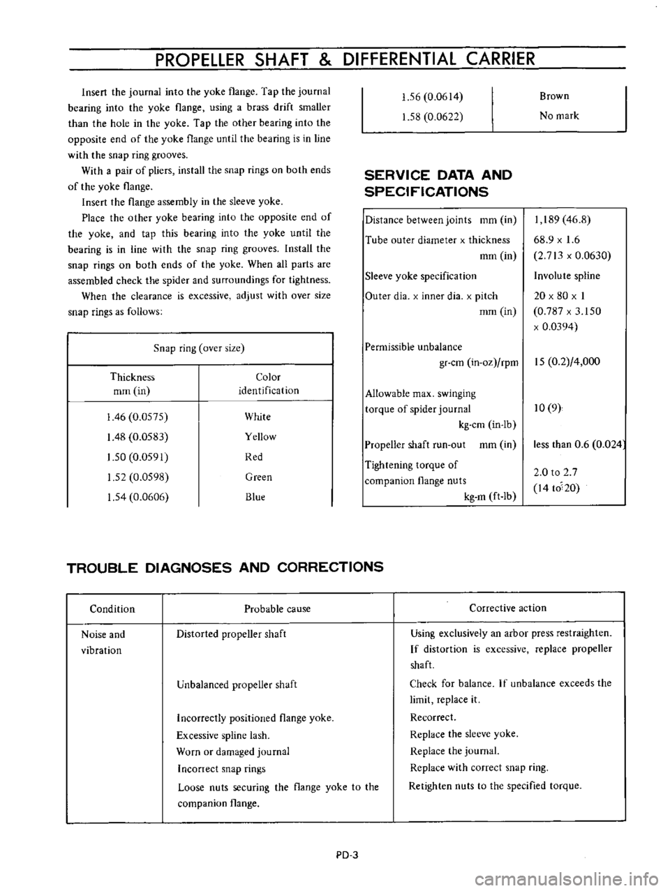
Snap
ring
over
size
Thickness
Color
mrn
in
identification
I
46
0
0575
White
I
48
0
0583
Yellow
1
50
0
0591
Red
1
52
0
0598
Green
1
54
0
0606
Blue
1
56
0
0614
1
58
0
0622
SERVICE
DATA
AND
SPECIFICATIONS
Distance
between
joints
mm
in
Tube
outer
diameter
x
thickness
mm
in
Sleeve
yoke
specification
Outer
dia
x
inner
dia
x
pitch
mm
in
Brown
No
mark
I
189
46
8
68
9
x
1
6
2
713
x
0
0630
Involute
spline
20
x
80
x
I
0
787
x
3
150
x
0
0394
Permissible
unbalance
gr
cm
in
oz
rpm
15
0
2
4
000
Allowable
max
swinging
torque
of
spider
journal
10
9
kg
cm
in
lb
Propeller
shaft
run
out
mm
in
Tightening
torque
of
companion
flange
nuts
kg
m
ft
Ib
TROUBLE
DIAGNOSES
AND
CORRECTIONS
Condition
Probable
cause
Noise
and
vibration
Distorted
propeller
shaft
Unbalanced
propeller
shaft
Corrective
action
less
than
0
6
0
024
2
0
to
2
7
I4
to
20
Using
exclusively
an
arbor
press
restraighten
If
distortion
is
excessive
replace
propeller
shaft
Check
for
balance
If
unbalance
exceeds
the
limit
replace
it
Recorrect
Replace
the
sleeve
yoke
Replace
the
journal
Replace
with
correct
snap
ring
Retighten
nuts
to
the
specified
torque
Incorrectly
positioned
flange
yoke
Excessive
spline
lash
Worn
or
damaged
journal
Inconect
snap
rings
Loose
nuts
securing
the
flange
yoke
to
the
companion
flange
PD
3
Page 83 of 513
CHASSIS
TROUBLE
DIAGNOSES
AND
CORRECTIONS
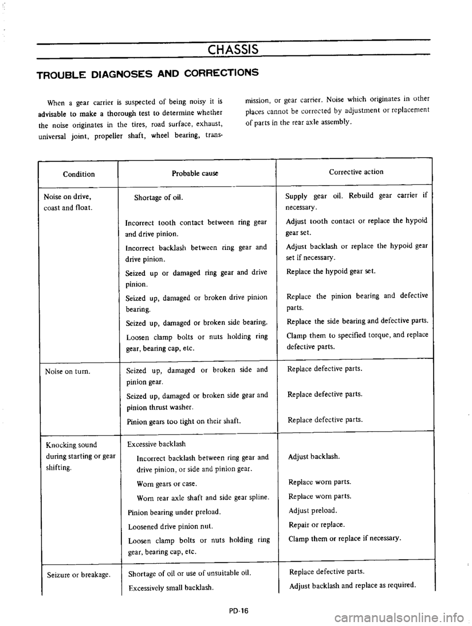
When
a
gear
carrier
is
suspected
of
being
noisy
it
is
advisable
to
make
a
thorough
test
to
determine
whether
the
noise
originates
in
the
tires
road
surface
exhaust
universal
joint
propeller
shaft
wheel
bearing
trans
Condition
Noise
on
drive
coast
and
float
Noise
on
turn
Knocking
sound
during
starting
or
gear
shifting
Seizure
or
breakage
mission
or
gear
carrier
Noise
which
originates
in
other
places
cannot
be
corrected
by
adjustment
or
replacement
of
parts
in
the
rear
axle
assembly
Probable
cause
Shortage
of
oil
Incorrect
tooth
contact
between
ring
gear
and
drive
pinion
Incorrect
backlash
between
ring
gear
and
drive
pinion
Seized
up
or
damaged
ring
gear
and
drive
pinion
Seized
up
damaged
or
broken
drive
pinion
bearing
Seized
up
damaged
or
broken
side
bearing
Loosen
clamp
bolts
or
nuts
holding
ring
gear
bearing
cap
etc
Seized
up
damaged
or
broken
side
and
pinion
gear
I
Seized
up
damaged
or
broken
side
gear
and
pinion
thrust
washer
Pinion
gears
too
tight
on
their
shaft
Excessive
backlash
Incorrect
backlash
between
ring
gear
and
drive
pinion
or
side
and
pinion
gear
Worn
gears
or
case
Worn
rear
axle
shaft
and
side
gear
spline
Pinion
bearing
under
preload
Loosened
drive
pinion
nut
Loosen
clamp
bolts
or
nuts
holding
ring
gear
bearing
cap
etc
Shortage
of
oil
or
use
of
unsuitable
oil
Excessively
small
backlash
PD
16
Corrective
action
Supply
gear
oil
Rebuild
gear
carrier
if
necessary
Adjust
tooth
contact
or
replace
the
hypoid
gear
set
Adjust
backlash
or
replace
the
hypoid
gear
set
if
necessary
Replace
the
hypoid
gear
set
Replace
the
pinion
bearing
and
defective
parts
Replace
the
side
bearing
and
defective
parts
Clamp
them
to
specified
torque
and
replace
defective
parts
Replace
defective
parts
Replace
defective
parts
Replace
defective
parts
Adjust
backlash
Replace
worn
parts
Replace
worn
parts
Adjust
preload
Repair
or
replace
Clamp
them
or
replace
if
necessary
Replace
defective
parts
Adjust
backlash
and
replace
as
required
Page 100 of 513
CHASSIS
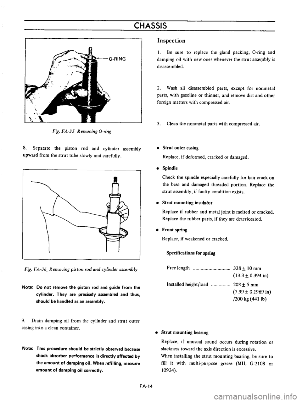
Fig
FA
35
Removing
O
ring
8
Separate
the
piston
rod
and
cyiinder
assembly
upward
from
the
strut
tube
slowly
and
carefully
M
Fig
FA
36
Removing
piston
rod
and
cylinder
assembly
Note
Do
not
remove
the
piston
rod
and
guide
from
the
cylinder
They
are
precisely
assembled
and
thus
should
be
handled
as
an
assembly
9
Drain
damping
oil
from
the
cylinder
and
strut
outer
casing
into
a
clean
container
Note
This
procedure
should
be
strictly
observed
because
shock
absorber
perlormance
is
directly
affected
by
the
amount
of
damping
oil
When
refilling
measure
amount
of
damping
oil
correctly
FA
14
Inspection
Be
sure
to
replace
the
gland
packing
O
ring
and
damping
oil
with
new
ones
whenever
the
strut
assetnb1y
is
disassembled
2
Wash
all
disassembled
parts
except
for
nonmetal
parts
with
gasoline
or
thinner
and
remove
dirt
and
other
foreign
matters
with
compressed
air
3
Clean
the
nonmetal
parts
with
compressed
air
Strut
outer
casing
Replace
if
deformed
cracked
or
damaged
Spindle
Check
the
spindle
especially
carefully
for
hair
crack
on
the
base
and
damaged
threaded
portion
Replace
the
strut
assembly
if
faulty
condition
exists
Strut
mounting
insulator
Replace
if
rubber
and
metal
joint
is
melted
or
cracked
Replace
the
rubber
parts
if
they
are
deteriorated
Front
spring
Replace
if
weakened
or
cracked
Specifications
for
spring
Free
length
338
t
10
mm
13
3
t
0
394
in
203
t
5
mm
7
99
t
0
1969
in
200
kg
441Ib
Installed
height
load
Strut
mounting
bearing
Replace
if
unusual
sound
occurs
during
rotation
or
slackness
toward
the
axis
direction
is
excessive
When
installing
the
strut
mounting
bearing
be
sure
to
fill
it
with
mul1i
purpose
grease
MIL
G
2108
or
10924
Page 102 of 513
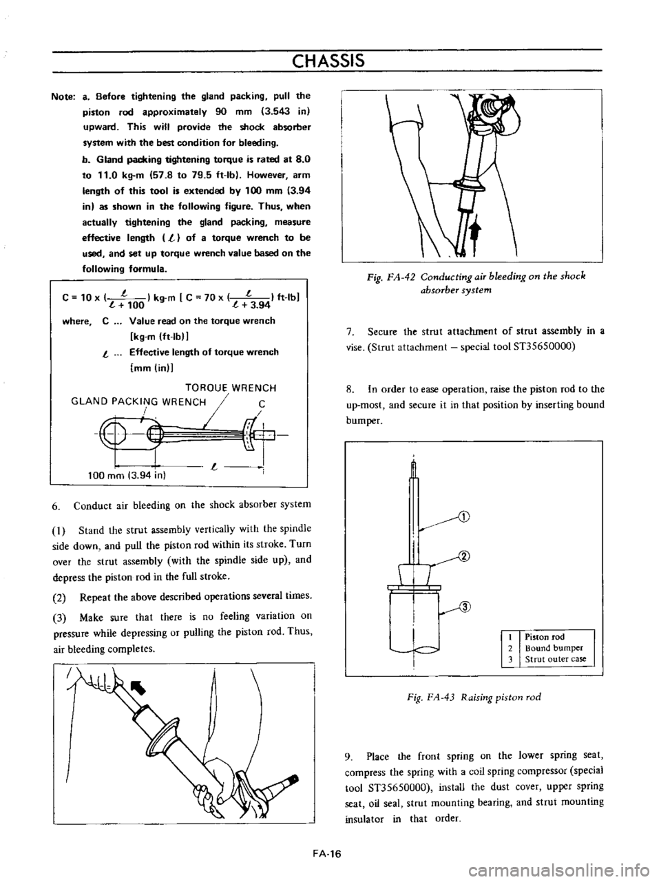
CHASSIS
Note
a
Before
tightening
the
gland
packing
pull
the
piston
rod
approximately
90
mm
3
543
in
upward
This
will
provide
the
shock
absorber
system
with
the
best
condition
for
bleeding
b
Gland
packing
tightening
torque
is
rated
at
8
0
to
11
0
kg
m
57
8
to
79
5
ft
Ib
However
arm
length
of
this
tool
is
extended
by
100
mm
3
94
in
as
shown
in
the
following
figure
Thus
when
actually
tightening
the
gland
packing
measure
effective
length
L
of
a
torque
wrench
to
be
used
and
set
up
torque
wrench
value
based
on
the
following
formula
C
10
x
l
I
kg
m
C
70
x
l
I
ft
lbJ
100
l
3
94
where
C
Value
read
on
the
torque
wrench
kg
m
ft
lbIJ
Effective
length
of
torque
wrench
mm
in
l
TOROUE
WRENCH
GLAND
PACKING
WRENCH
I
C
4
F
r
I
L
I
100
mm
3
94
in
6
Conduct
air
bleeding
on
the
shock
absorber
system
1
Stand
the
strut
assembly
vertically
with
the
spindle
side
down
and
pull
the
piston
rod
within
its
stroke
Turn
over
the
strut
assembly
with
the
spindle
side
up
and
depress
the
piston
rod
in
the
full
stroke
2
Repeat
the
above
described
operations
several
times
3
Make
sure
that
there
is
no
feeling
variation
on
pressure
while
depressing
or
pulling
the
piston
rod
Thus
air
bleeding
completes
J
FA
16
Fig
FA
42
ConductingaiT
bleeding
on
the
shock
absorber
system
7
Secure
the
strut
attachment
of
strut
assembly
in
a
vise
Strut
attachment
special
tool
Sn5650000
8
In
order
to
ease
operation
raise
the
piston
rod
to
the
up
most
and
secure
it
in
that
position
by
inserting
bound
bum
per
t
D
I
T
I
c
I
Piston
rod
2
Bound
bumper
3
Strut
outer
case
Fig
FA
43
Raising
piston
rod
9
Place
the
front
spring
on
the
lower
spring
seat
compress
the
spring
with
a
coil
spring
compressor
special
tool
Sn5650000
install
the
dust
cover
upper
spring
seat
oil
seal
strut
mounting
bearing
and
strut
mounting
insulator
in
that
order