1973 DATSUN B110 air condition
[x] Cancel search: air conditionPage 111 of 513
FRONT
AXLE
FRONT
SUSPENSION
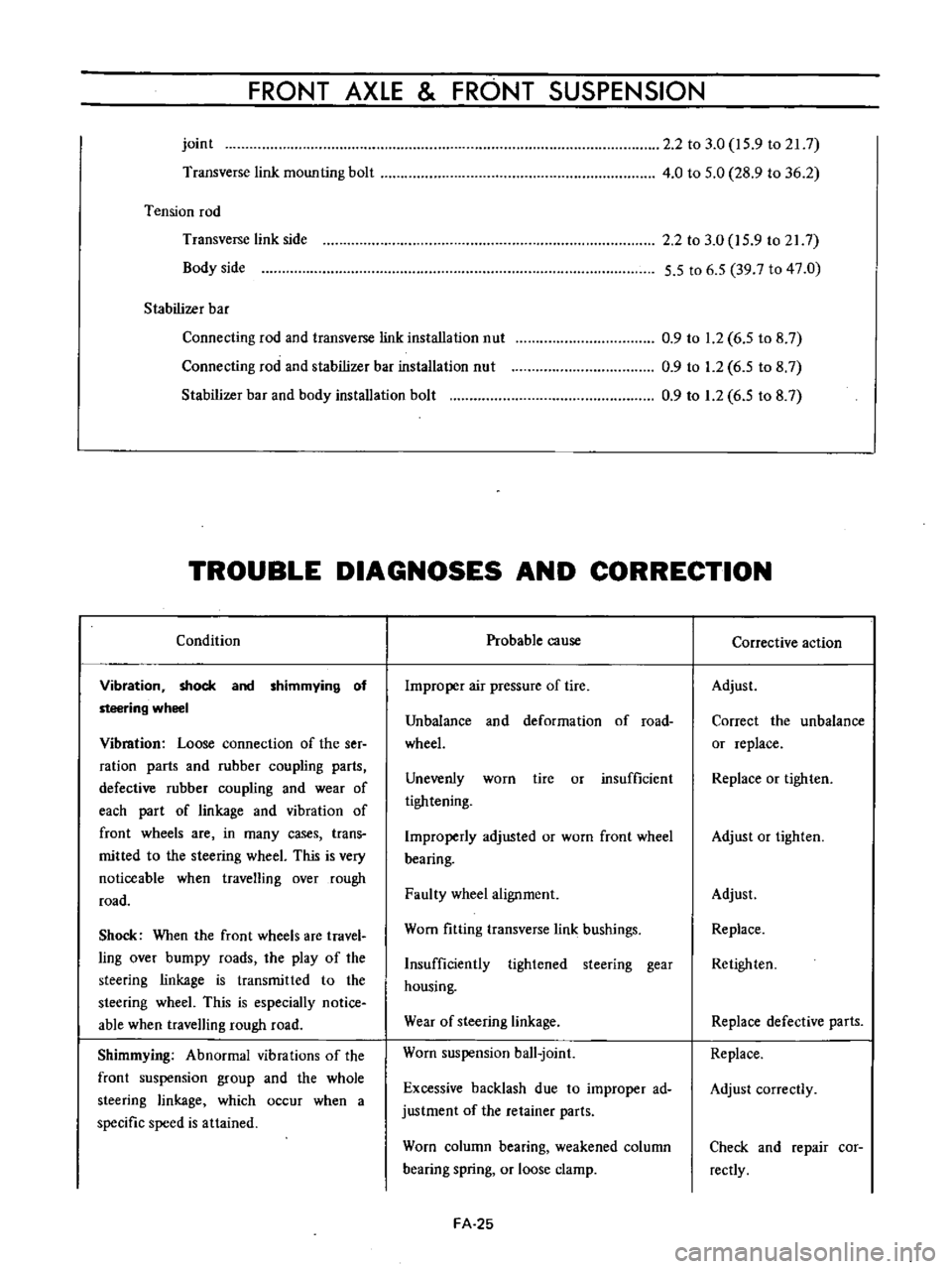
joint
Transverse
link
mounting
bolt
Tension
rod
Transverse
link
side
Body
side
Stabilizer
bar
Connecting
rod
and
transverse
link
installation
nut
Connecting
rod
and
stabilizer
bar
installation
nut
Stabilizer
bar
and
body
installation
bolt
2
2
to
3
0
15
9
to
21
7
4
0
to
5
0
28
9
to
36
2
2
2
to
3
0
15
9
to
217
5
5
to
6
5
39
7
to
47
0
0
9
to
1
2
6
5
to
8
7
0
9
to
1
2
6
5
to
8
7
0
9
to
1
2
6
5
to
8
7
TROUBLE
DIAGNOSES
AND
CORRECTION
Condition
Vibration
shock
and
shimmying
of
steering
wheel
Vibmtion
Loose
connection
of
the
ser
ration
parts
and
rubber
coupling
parts
defective
rubber
coupling
and
wear
of
each
part
of
linkage
and
vibration
of
front
wheels
are
in
many
cases
trans
mitted
to
the
steering
wheeL
This
is
very
noticeable
when
travelling
over
rough
road
Shock
When
the
front
wheels
are
travel
ling
over
bumpy
roads
the
play
of
the
steering
linkage
is
transmitted
to
the
steering
wheeL
This
is
especially
notice
able
when
travelling
rough
road
Shimmying
Abnormal
vibrations
of
the
front
suspension
group
and
the
whole
steering
linkage
which
occur
when
a
specific
speed
is
attained
Probable
cause
Improper
air
pressure
of
tire
Unbalance
and
deformation
of
road
wheeL
Unevenly
worn
tire
or
insufficient
tightening
Improperly
adjusted
or
worn
front
wheel
bearing
Faulty
wheel
alignment
Worn
fitting
transverse
link
bushings
Insufficiently
tightened
steering
gear
housing
Wear
of
steering
linkage
Worn
suspension
ball
joint
Excessive
backlash
due
to
improper
ad
justment
of
the
retainer
parts
Worn
column
bearing
weakened
column
bearing
spring
or
loose
clamp
FA
25
Corrective
action
Adjust
Correct
the
unbalance
or
replace
Replace
or
tighten
Adjust
or
tighten
Adjust
Replace
Retighten
Replace
defective
parts
Replace
Adjust
correctly
Check
and
repair
cor
rectly
Page 128 of 513
CHASSIS
Ii
t
L
1
J
rJ
I
e
i
L
rubber
parts
und
alcohol
long
than
30
seconds
After
the
parts
are
cleaned
dry
them
with
com
pressed
air
Check
the
cylinder
and
piston
for
damage
and
uneven
wear
on
the
sliding
surface
and
for
other
defective
conditions
Replace
as
required
2
Replace
if
the
cylinder
and
piston
clearance
is
more
than
0
15
mm
0
006
in
3
In
principle
replace
the
piston
cup
packing
and
valves
with
new
ones
whenever
the
master
cylinder
is
disassembled
Be
sure
to
replace
if
damaged
worn
weakened
or
expanded
4
Check
the
return
springs
for
wear
damage
and
other
defective
conditions
and
replace
as
required
5
Replace
others
if
deformed
damaged
or
defective
Reassembly
Assemble
the
master
cylinder
in
reverse
sequence
of
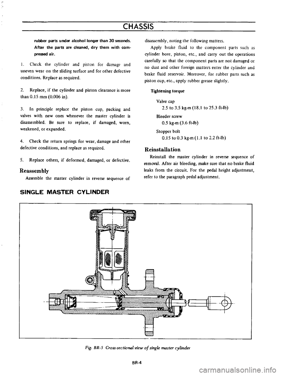
SINGLE
MASTER
CYLINDER
s
m
e
disassembly
noting
the
following
matters
Apply
brake
fluid
to
the
component
parts
such
as
cylinder
bore
piston
etc
and
carry
out
the
operations
carefully
so
that
the
component
parts
are
not
damaged
or
no
dust
and
other
foreign
matters
enter
the
cylinder
and
brake
fluid
reselVoir
Moreover
for
rubber
parts
such
as
piston
cup
etc
apply
rubber
grease
slightly
Tightening
torque
Valve
cap
2
5
to
3
5
kg
m
I8
to
25
3
ft
Ib
Bleeder
screw
0
5
kg
m
3
6
ft
lb
Stopper
bolt
0
5
to
0
3
kg
m
l
I
to
2
2ft
lb
Reinstallation
Reinstall
the
master
cylinder
in
reverse
sequence
of
removal
After
air
bleeding
make
sure
that
no
brake
fluid
leaks
from
the
circuit
For
the
pedal
height
adjustment
refer
to
lhe
paragraph
pedal
adjustment
r
11L
y
Fig
BR
5
Cross
sectional
view
of
single
master
cylinder
BR
4
Page 133 of 513
7
Remove
the
brake
disc
installation
bolt
and
remove
the
brake
disc
from
the
spindle
8
Disassemble
the
wheel
cylinders
Inspection
l
Drums
If
they
show
score
excessive
out
of
round
and
so
forth
reconditioning
by
machining
is
required
Brake
drum
inner
diameter
203
2
mm
8
00
in
Drum
inside
out
of
roundness
Below
0
02
mm
0
0008
in
Max
allowable
drum
inner
diameter
204
5
mm
8
051
in
2
Linings
If
brake
shoe
linings
are
incomp1etedly
seated
soiled
or
greasy
or
deteriorated
due
to
excessive
heating
repair
or
replace
them
If
the
thickness
of
the
lining
is
less
than
1
5
mm
0
0591
in
replace
it
Note
a
If
oil
or
grease
is
found
on
linings
clean
thoroughly
with
carbon
tetrachloride
or
gasoline
b
After
installing
and
bonding
lining
grind
the
lining
face
to
a
diameter
equal
to
the
brake
drum
3
Check
the
adjusting
cams
for
their
smooth
operation
4
Return
springs
If
they
are
considerably
weak
replace
them
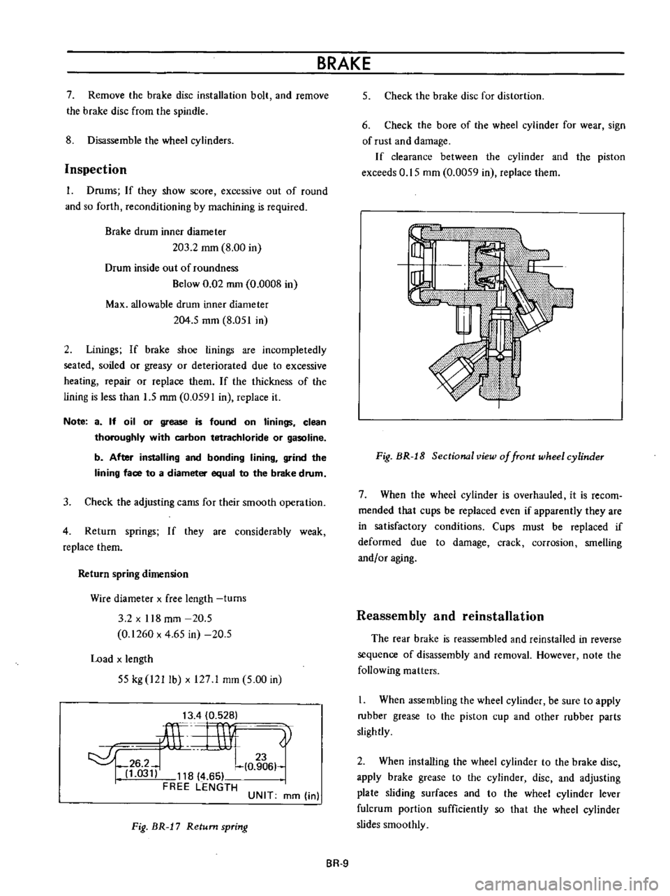
Return
spring
dimension
Wire
diameter
x
free
length
turns
3
2
x
118
mm
20
5
0
1260
x
4
65
in
20
5
Load
x
length
55
kg
I21
lb
x
127
1
mm
5
00
in
13
4
0
528
ilL
rnv
0
t
6
hl
03
118
4
65
FREE
LENGTH
UNIT
mm
in
Fig
BR
J
7
Return
spring
BRAKE
5
Check
the
brake
disc
for
distortion
6
Check
the
bore
of
the
wheel
cylinder
for
wear
sign
of
rust
and
damage
If
clearance
between
the
cylinder
and
the
piston
exceeds
0
15
mm
0
0059
in
replace
them
Fig
BR
J
8
Sectional
view
of
front
wheel
cylinder
7
When
the
wheel
cylinder
is
overhauled
it
is
recom
mended
that
cups
be
replaced
even
if
apparently
they
are
in
satisfactory
conditions
Cups
must
be
replaced
if
deformed
due
to
damage
crack
corrosion
smelling
andf
or
aging
Reassembly
and
reinstallation
The
rear
brake
is
reassembled
and
reinstalled
in
reverse
sequence
of
disassembly
and
removal
However
note
the
following
matters
When
assembling
the
wheel
cylinder
be
sure
to
apply
rubber
grease
to
the
piston
cup
and
other
rubber
parts
slightly
2
When
installing
the
wheel
cylinder
to
the
brake
disc
apply
brake
grease
to
the
cylinder
disc
and
adjusting
plate
sliding
surfaces
and
to
the
wheel
cylinder
lever
fulcrum
portion
sufficiently
so
that
the
wheel
cylinder
slides
smoothly
BR
9
Page 148 of 513
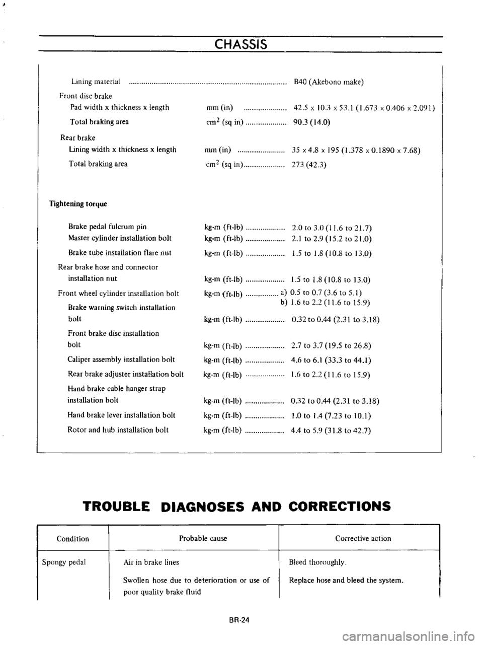
Lining
material
Front
disc
brake
Pad
width
x
thickness
x
length
Total
braking
area
Rear
brake
Lining
width
x
thickness
x
length
Total
braking
area
Tightening
torque
Brake
pedal
fulcrum
pin
Master
cylinder
installation
bolt
Brake
tube
installation
flare
nut
Rear
brake
hose
and
connector
installation
nut
Front
wheel
cylinder
installation
bolt
Brake
warning
switch
installation
bolt
Front
brake
disc
installation
bolt
Caliper
assembly
installation
bolt
Rear
brake
adjuster
installation
bolt
Hand
brake
cable
hanger
strap
installation
bolt
Hand
brake
lever
installation
bolt
Rotor
and
hub
installation
bolt
CHASSIS
mm
in
cm2
sq
in
mm
in
cm2
sq
in
kg
m
ft
1b
kg
m
ft
lb
kg
m
ft
lb
kg
m
ft
lb
kg
m
ft
lb
kg
m
ft
lb
kg
m
ft
lb
kg
m
ft
lb
kg
m
ft
lb
kg
m
ft
lb
kg
m
ft
lb
kg
m
ft
Ib
B40
Akebuno
make
42
5
x
10
3
x
53
I
1
673
x
0
406
x
2
091
90
3
14
0
35
x
4
8
x
195
1
378
x
0
1890
x
7
68
273
42
3
2
0
to
3
0
11
6
to
217
2
1
to
2
9
15
2
to
21
0
1
5
to
1
8
l
0
8
to
13
0
1
5
to
1
8
10
8
to
13
0
a
0
5
to
0
7
3
6
to
5
I
b
1
6
to
2
2
I
1
6
to
15
9
0
32
to
0
44
2
31
to
3
18
2
7
to
3
7
19
5
to
26
8
4
6
to
6
1
33
3
to
44
1
1
6
to
2
2
11
6
to
15
9
0
32
to
0
44
2
31
to
3
18
1
0
to
I
4
7
23
to
10
1
44
to
59
31
8
to
42
7
TROUBLE
DIAGNOSES
AND
CORRECTIONS
Condition
Spongy
pedal
Air
in
brake
lines
Probable
cause
Swollen
hose
due
to
deterioration
or
use
of
poor
quality
brake
fluid
BR
24
Corrective
action
Bleed
thoroughly
Replace
hose
and
bleed
the
system
Page 156 of 513
WHEEL
AND
TIRE
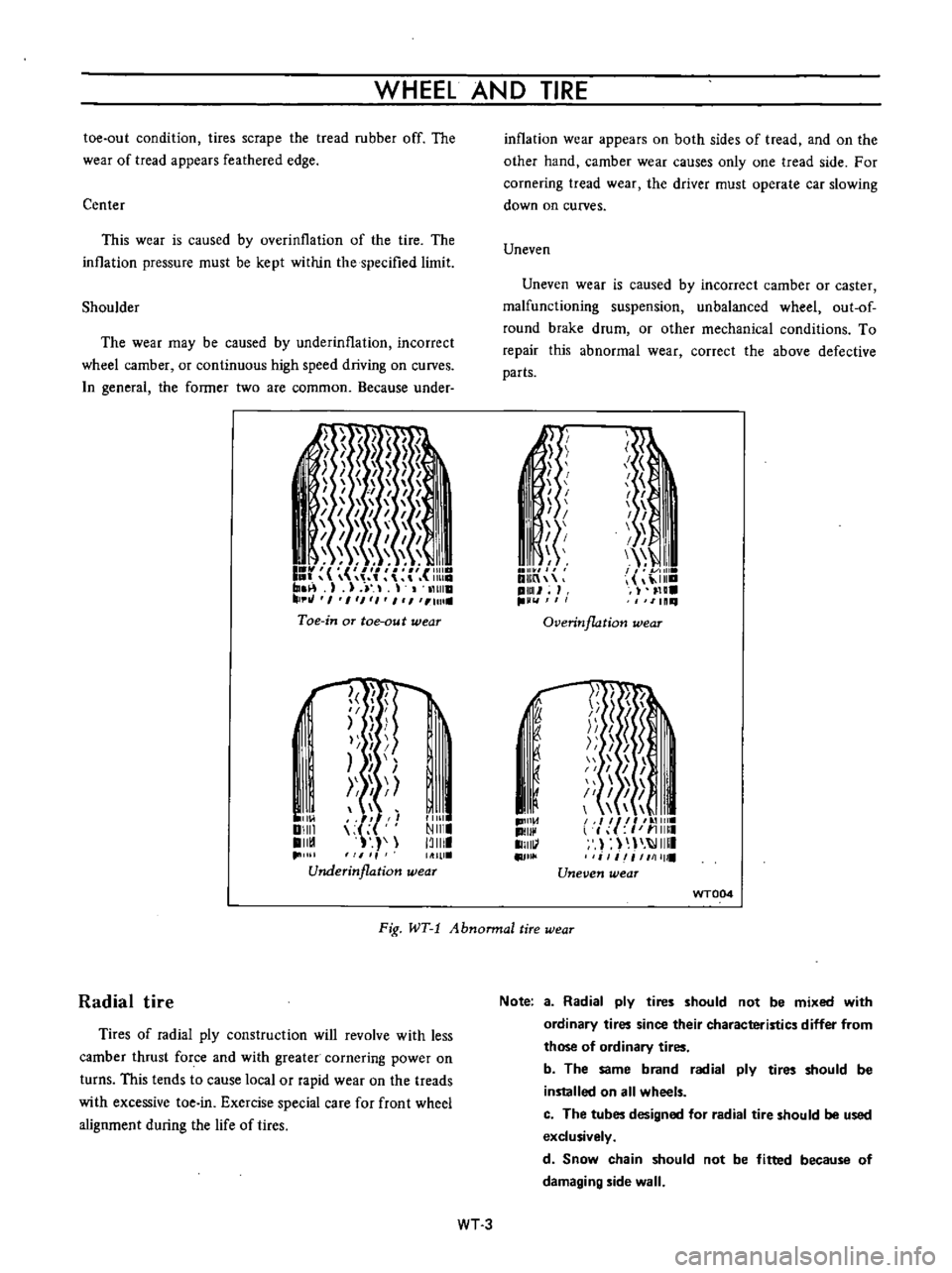
toe
out
condition
tires
scrape
the
tread
rubber
off
The
wear
of
tread
appears
feathered
edge
Center
This
wear
is
caused
by
overinllation
of
the
tire
The
inllation
pressure
must
be
kept
within
the
specified
limit
Shoulder
The
wear
may
be
caused
by
underinflation
incorrect
wheel
camber
or
continuous
high
speed
driving
on
curves
n
general
the
former
two
are
common
Because
under
I
I
I
I
1
1111
I
r
r
m
1
J
11
tHlla
tJ
I
1
1
1
I
1
Ull
Toe
in
aT
toe
au
t
wear
l
f
I
II
I
I
I
I
Ill
Ill
Underinflation
wear
I
11
01
DIIII
II
1
11111
NIII
13111
inflation
wear
appears
on
both
sides
of
tread
and
on
the
other
hand
camber
wear
causes
only
one
tread
side
For
cornering
tread
wear
the
driver
must
operate
car
slowing
down
on
curves
Uneven
Uneven
wear
is
caused
by
incorrect
camber
or
caster
malfunctioning
suspension
unbalanced
wheel
out
of
round
brake
drum
or
other
mechanical
conditions
To
repair
this
abnormal
wear
correct
the
above
defective
parts
Ii
I
I
I
I
1
i
f
I
I
I
I
I
III
I
I
11
DlIIn
ilia
pml
H
IlLl
11111
Overinflation
wear
1D1I1
d
II
1I111
II
j
J
1
51
I
I
I
1
il
I
I
II
l
f
I
11
11111
I
IIIII
i
1
iI
1111111
Uneven
wear
f
I
I
u
WT004
Fig
WT
1
Abnonnal
tire
wear
Radial
tire
Tires
of
radial
ply
construction
will
revolve
with
less
camber
thrust
force
and
with
greater
cornering
power
on
turns
This
tends
to
cause
local
or
rapid
wear
on
the
treads
with
excessive
toe
in
Exercise
special
care
for
front
wheel
alignment
during
the
life
of
tires
Note
a
Radial
ply
tires
should
not
be
mixed
with
ordinary
tires
since
their
characteristics
differ
from
those
of
ordinary
tires
b
The
same
brand
radial
ply
tires
should
be
installed
on
all
wheels
c
The
tubes
designed
for
radial
tire
should
be
used
exclusively
d
Snow
chain
should
not
be
fitted
because
of
damaging
side
wall
WT3
Page 157 of 513

CHASSIS
Tire
rotation
Tires
wear
unevenly
and
become
unbalanced
according
to
running
distance
Uneven
tire
wear
often
results
in
tire
noise
whkh
is
attributed
to
rear
axle
gears
bearing
ell
Meanwhile
the
front
tires
tend
to
wear
unevenly
because
of
front
wheel
alignment
Accordingly
to
equalize
tire
wear
it
is
necessary
to
rotate
tires
every
10
000
km
6
000
miles
of
operation
RIGHT
FRONT
RIGHT
REAR
r
1
Xl
L
J
LEFT
FRONT
LEFT
REAR
Fig
WT
2
Tire
rotation
The
tires
are
provided
with
tread
wear
indicator
at
six
places
around
tire
circumference
indicating
1
6
nun
0
16
in
tread
depth
When
the
tires
wear
and
then
the
marks
a
ppear
replace
them
with
new
ones
TREAD
WEAR
INDICATOR
7
TREAD
m
Y
X
W
X
v
w
WH024
Fig
WI
3
Tread
wear
illdicator
To
change
tire
with
wheel
using
a
jack
in
the
safe
manner
observe
the
following
procedures
I
Apply
parking
brake
and
block
front
wheels
when
rear
wheel
is
being
changed
2
Remove
wheel
cap
and
loosen
wheel
nuts
3
Place
jack
at
jacking
point
instructed
under
General
Information
and
raise
car
until
wheel
clears
ground
4
Remove
wheel
nuts
and
whed
from
drum
5
To
install
wheel
reverse
the
above
steps
Tighten
whed
nuts
in
criss
cross
fashion
to
8
0
to
9
0
kg
m
58
to
65
ft
lb
Note
Never
get
under
the
car
while
it
is
supported
only
by
the
jack
Always
use
safety
stands
to
support
the
side
member
of
body
construction
when
you
must
get
beneath
the
car
INSPECTION
Wheel
balance
The
wheel
and
tire
assembly
should
be
kept
balanced
statically
and
dynamically
Proper
tire
balance
is
necessary
when
driving
the
car
at
high
speeds
Consequently
the
wheel
and
tire
assembly
should
be
properly
rebalanced
whenever
puncture
is
repaired
The
wheel
and
tire
assembly
becomes
out
of
balance
according
to
uneven
tire
wear
Severe
acceleration
and
braking
or
fast
cornering
is
the
cause
of
wear
on
tire
resulting
in
unbalance
of
tire
and
wheel
assembly
The
symptom
of
unbalance
appears
as
tramp
car
shake
and
steering
trouble
To
correct
unbalance
use
proper
wheel
balancer
Maximum
allowable
unbalance
165
gr
cm
2
3
in
ol
at
rim
circumferences
Balance
weight
10
to
70
gr
0
35
to
2
47
Ol
at
10
gr
0
35
Ol
interval
Note
Be
sure
to
place
the
correct
balance
weights
on
the
inner
edge
of
rim
as
shown
in
Figure
WT
4
Wheel
and
tire
In
order
to
ensure
satisfactory
steering
condition
as
well
as
maximum
tire
life
proceed
as
follows
I
Check
wheel
rim
especially
rim
flange
and
bead
seat
for
rust
distortion
cracks
or
other
defects
which
might
cause
air
leaks
Function
of
tubeless
tire
depends
on
a
good
seal
between
tire
bead
and
wheel
rim
Thoroughly
remove
rust
dust
oxidized
rubber
or
sand
from
wheel
rim
with
wire
brush
emery
cloth
or
paper
Use
dial
gauge
to
examine
wheel
rim
for
lateral
and
diametral
run
out
WT
4
Page 158 of 513
WHEEL
AND
TIRE
Note
In
replacing
tire
take
extra
care
not
to
damage
tire
bead
rim
flange
and
bead
seat
Do
not
use
tire
irons
to
force
beads
away
from
wheel
rim
flange
that
is
always
use
tire
replace
ment
device
whenever
tire
is
removed
WT005
2
Discard
when
any
of
the
following
trouble
occurs
I
Broken
or
damaged
bead
wire
2
Ply
or
tread
separation
3
Worn
febric
damage
on
tubeless
tire
4
Cracked
or
damaged
side
wall
etc
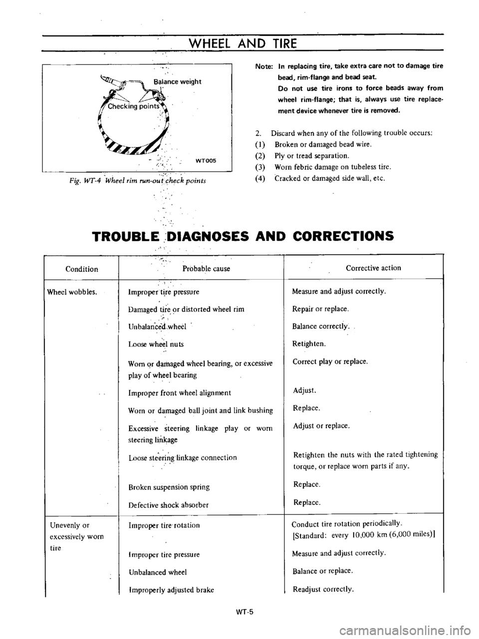
Fig
WT
4
Wheel
rim
run
out
heck
points
TROUBLE
DIAGNOSES
AND
CORRECTIONS
Condition
Probable
cause
Corrective
action
Wheel
wobbles
Improper
t
re
pressure
Measure
and
adjust
correctly
Damaged
tire
9f
distorted
wheel
rim
Repair
or
replace
UnbalanceiLwheel
Balance
correctly
Loose
wheel
nuts
Retighten
Worn
qr
damaged
wheel
bearing
or
excessive
play
of
wheel
bearing
Correct
play
or
replace
Improper
front
wheel
alignment
Adjust
Worn
or
damaged
ball
joint
and
link
bushing
Replace
Excessive
steering
linkage
play
or
worn
steering
lin
age
Adjust
or
replace
Loose
stcerin
linkage
connection
Retighten
the
nuts
with
the
rated
lightening
torque
or
replace
worn
parts
if
any
Broken
suspension
spring
Replace
Defective
shock
absorber
Replace
Unevenly
or
excessively
worn
tire
Improper
tire
rotation
Conduct
tire
rotation
periodically
Standard
every
10
000
km
6
000
miies
Improper
tire
pressure
Measure
and
adjust
correctly
Unbalanced
wheel
Balance
or
replace
Improperly
adjusled
brake
Readjust
correctly
WT5
Page 175 of 513
fJ
J
STEERING
INSPECTION
AND
REPAIR
I
Check
the
idler
rubber
bushing
for
damage
wear
and
play
and
replace
bushing
if
necessary
2
Check
the
cross
rod
and
side
rods
for
damage
bend
and
crack
and
replace
them
if
necessary
3
Check
each
ball
joints
for
play
due
to
lack
of
spring
action
of
the
push
spring
or
a
damaged
ball
stud
11
I
Ball
stud
2
Dust
cover
143
I
Clamp
Spring
seat
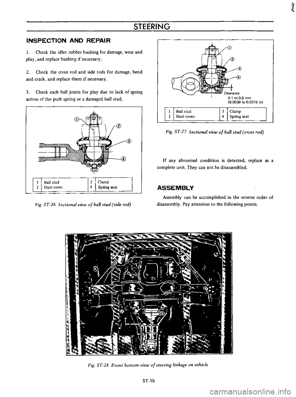
Fig
ST
27
Sectional
view
of
ball
stud
cross
rod
If
any
abnormal
condition
is
detected
replace
as
a
complete
unit
They
can
not
be
disassembled
I
I
Ball
stud
Dust
cover
13
I
Clamp
4
Spring
seat
ASSEMBLY
FiJI
ST
26
Sectional
view
of
ball
stud
side
rod
Assembly
can
be
accomplished
in
the
reverse
order
of
disassernbly
Pay
attention
to
the
following
points
l
I
f
t
ljo
Fig
ST
28
Front
bottom
view
of
steeritJg
linkage
on
vehicle
ST
15