1973 DATSUN B110 air condition
[x] Cancel search: air conditionPage 267 of 513
BODY
RADIO
Removal
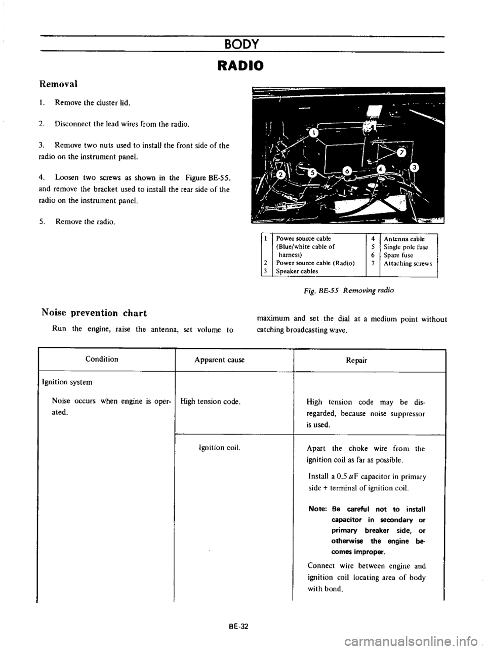
Remove
he
cluster
lid
2
Disconnect
the
lead
wires
from
the
radio
3
Remove
two
nuts
used
to
install
the
front
side
of
the
radio
on
the
instrument
panel
4
Loosen
two
screws
as
shown
in
the
Figure
BE
55
and
remove
the
bracket
used
to
install
the
rear
side
of
the
radio
on
the
instrument
panel
5
Remove
the
radio
Noise
prevention
chart
Run
the
engine
raise
the
antenna
set
volume
to
Condition
Apparent
cause
Ignition
system
Noise
occurs
when
engine
is
oper
High
tension
code
ated
Ignition
coil
i
O
i
M
1
iiJ
1
7
L
l
o
f
I
ft
V
r
1
1
v
I
I
t
i
J
iL
1
Power
soutee
cable
Blue
white
cable
of
harness
2
Power
source
cable
Radio
3
Speaker
cables
4
Antenna
cable
5
Single
pole
fuse
6
Spare
fuse
7
Attaching
screws
Fig
BE
55
Removing
radio
maximum
and
set
the
dial
at
a
medium
point
without
catching
broadcasting
wave
Repair
High
tension
code
may
be
dis
regarded
because
noise
suppressor
is
used
Apart
the
choke
wire
frorn
the
ignition
coil
as
far
as
possible
Install
a
0
5
uF
capacitor
in
primary
side
terminal
of
ignition
coil
Note
8e
careful
not
to
install
capacitor
in
secondary
or
primary
breaker
side
or
otherwise
the
engine
be
comes
improper
Connect
wire
between
engine
and
ignition
coil
locating
area
of
body
with
bond
BE
32
Page 270 of 513
BODY
ELECTRICAL
heater
unit
on
the
dash
board
and
remove
the
heater
unit
carefully
panel
8
Rernove
two
self
tapping
screws
from
back
of
the
instrument
panel
and
remove
the
defroster
nozzle
7
When
removing
the
heater
control
from
the
instru
ment
panel
remove
the
control
knob
and
loosen
two
screws
used
to
install
the
heater
control
on
the
instrument
9
The
heater
unit
is
installed
in
reverse
sequence
of
removal
TROUBLE
DIAGNOSES
AND
CORRECTIONS
Condition
Probable
cause
Hot
air
does
not
come
out
Motor
does
not
operate
Open
or
short
circuit
of
feed
har
ness
Defective
switch
Defective
motor
Fan
cannot
be
rotated
smoothly
by
hand
Motor
journal
is
out
of
lubricant
or
stick
Hot
air
dose
not
come
out
nevertheless
fan
is
rotating
Slow
rotation
of
fan
Loose
fan
installation
Air
temperature
is
low
Hot
water
does
not
cir
culate
Defective
water
pump
Bent
or
clogged
of
connecting
hose
Defective
hot
water
cock
Air
is
left
in
the
hose
Water
temperature
is
too
low
Defective
thermostat
Water
leakage
from
heater
Defective
water
hose
Loose
clipping
of
water
hose
Improper
soldering
of
heater
core
Defective
defroster
Disconnected
defroster
hose
Bent
or
broken
defroster
hose
BE
35
Corrective
action
Check
and
repair
wiring
harness
Conduct
continuity
test
and
if
required
replace
switch
Replace
motor
Lubricate
journal
Replace
motor
Replace
motor
Repair
Repair
water
pump
Repair
or
clean
piping
Repair
Purge
air
out
of
hose
Replace
thermostat
Replace
water
hose
Retighten
clip
Solder
leaking
position
Correct
connection
Correct
or
replace
Page 310 of 513

EMISSION
CONTROL
AND
TUNE
UP
reading
cylinders
through
spark
plug
hole
Repeat
compression
check
on
these
cylinders
1
If
compression
improves
considerably
piston
rings
are
defective
2
If
compression
does
not
improve
valves
are
sticking
or
seating
improperly
3
If
two
adjacent
cylinders
indicate
low
compression
and
injecting
oil
on
pistons
does
not
increase
compres
sion
the
cause
may
be
a
cylinder
head
gasket
leak
between
the
cylinders
Engine
oil
and
coolant
in
cylinder
could
result
from
this
problem
Compression
pressure
12
S
to
14
S
kg
cm2
178
to
206
psi
at
3S0
rpm
Checking
exhaust
manifold
heat
control
valve
Check
heat
control
valve
for
proper
operation
If
it
does
not
operate
properly
trouble
is
due
to
excess
carbon
on
shaft
or
damaged
shaft
Clean
if
necessary
The
bimetal
should
be
also
checked
for
proper
function
IGNITION
AND
FUEL
SYSTEM
Checking
battery
Check
electrolyte
level
in
each
battery
celL
L
Unscrew
each
filler
cap
and
inspect
fluid
leveL
If
fluid
level
is
low
add
distilled
water
to
bring
level
up
to
app
roximately
10
to
20
mm
0
3937
to
0
7874
in
above
plates
Do
not
overfilL
2
Measure
specific
gravity
of
battery
electrolyte
ET002
Fig
ET
B
Checking
the
specific
gravity
of
battery
electrolyte
Permissible
Full
charge
value
value
at
200C
68OF
Frigid
climates
Over
1
22
1
28
Tropical
climates
Over
1
18
1
23
Other
climates
Over
L
20
1
26
Clean
the
top
of
battery
and
terminals
with
a
solu
lion
of
baking
soda
and
water
Rinse
off
and
dry
with
compressed
air
The
top
of
battery
must
be
clean
to
prevent
current
leakage
between
terminals
and
from
positive
terminal
to
hold
down
clamp
In
addition
to
current
leakage
prolonged
accumulation
of
acid
and
dirt
on
the
top
of
battery
may
cause
blistering
of
the
material
covering
connector
straps
and
corrosion
of
straps
After
tightening
terminals
coat
them
with
petro
laturn
vaseline
to
protect
them
from
corrosion
Checking
and
adjusting
ignition
timing
I
Check
spark
plugs
and
distributor
breaker
points
for
condition
2
Thoroughly
wipe
off
dirt
and
dust
from
timing
marks
on
crank
pulley
and
front
cover
3
Warm
up
engine
sufficiently
ET
5
Page 312 of 513

EMISSION
CONTROL
AND
TUNE
UP
Fig
ET
11
Checking
spark
plug
gap
Checking
distributor
ignition
wiring
and
ignition
coil
Distributor
Check
centrifugal
advance
unit
for
loose
connection
or
improper
operation
If
it
is
not
operating
properly
the
trouble
may
be
due
to
a
sticky
spring
or
excessively
worn
parts
This
operation
needs
a
distributor
tester
As
to
inspection
procedure
and
reference
data
refer
to
relative
topic
under
Distributor
in
Section
EE
Page
EE
32
If
vacuum
advance
mechanism
fails
to
operate
proJr
erly
check
for
the
following
items
and
correct
the
trouble
as
required
1
Check
vacuum
inlet
for
signs
of
leakage
at
its
connection
If
necessary
retighten
or
replace
with
a
new
one
2
Check
vacuum
diaphragm
for
air
leak
If
leak
is
found
replace
diaphragm
with
a
new
one
3
Inspect
breaker
plate
for
smooth
moving
If
plate
does
not
move
smoothly
this
condition
could
be
due
to
sticky
steel
balls
or
pivot
Apply
grease
to
steel
balls
or
if
necessary
replace
breaker
plate
as
an
assembly
For
vacuum
advance
characteristics
refer
to
Distribu
tor
in
Section
EE
Page
EE
32
Ignition
wiring
Use
an
ohmmeter
to
check
resistance
of
secondary
cables
Disconnect
cables
from
spark
plugs
and
install
the
proper
adapter
between
cable
and
spark
plug
Remove
distributor
cap
from
the
distributor
with
secondary
cables
attached
Do
not
remove
the
cables
from
the
cap
Check
the
resistance
of
one
cable
at
a
time
Connect
the
ohmmeter
between
the
spark
plug
adapter
and
the
corresponding
electrode
inside
the
cap
If
resistance
is
more
than
30
000
ohms
remove
the
cable
from
the
cap
and
check
cable
resistance
only
If
the
resistance
is
still
more
than
30
000
ohms
replace
cable
assembly
T
I
II
Fig
ET
12
Checking
high
tension
cables
Ignition
coil
Check
ignition
coil
for
appearance
oil
leakage
or
performance
For
details
refer
to
Section
EE
Page
EE36
Checking
distributor
cap
and
rotor
Note
This
operation
is
to
be
performed
while
chekcing
distribuotr
points
Inspect
distributor
cap
for
cracks
and
flash
over
External
surfaces
of
all
parts
of
secondary
system
must
be
cleaned
to
reduce
possibility
of
voltage
loss
All
wires
should
be
removed
from
distributor
cap
and
coil
so
that
terminals
can
be
inspected
and
cleaned
Burned
or
corroded
terminals
indicate
that
wires
were
not
fully
seated
which
causes
arcing
between
end
of
wire
and
terminal
When
replacing
wires
in
terminal
be
sure
they
are
fully
seated
before
pushing
rubber
nipple
down
over
tower
Check
distributor
rotor
for
damage
and
distributor
cap
for
cracks
ET
7
Page 314 of 513

EMISSION
CONTROL
AND
TUNE
UP
Checking
and
adjusting
dash
pot
automatic
transmission
model
only
Check
operation
of
dash
pot
It
should
not
be
cracked
or
bound
It
is
also
essential
to
check
to
be
certain
that
it
is
in
correct
adjustment
L
Check
to
be
sure
that
dash
pot
contacts
stopper
lever
when
engine
speed
reaches
1
900
to
2
000
rpm
2
Engine
should
be
slowed
down
from
3
000
to
1
000
rpm
within
a
few
seconds
Readjust
dash
pot
or
replace
it
with
a
new
one
if
it
fails
to
meet
the
above
conditions
Checking
carburetor
return
spring
Check
throttle
return
spring
for
sign
of
damage
wear
or
squareness
Discard
spring
if
found
with
any
of
above
excessively
beyond
use
Checking
choke
mechanism
choke
valve
and
linkage
1
Check
choke
valve
and
mechanism
for
free
operation
and
clean
or
replace
if
necessary
A
binding
condition
may
have
developed
from
petro
leum
gum
for
motion
on
choke
shaft
or
from
damage
2
Check
bimetal
cover
setting
position
The
index
mark
of
bimetal
cover
is
usually
aligned
at
the
middle
point
of
the
scale
Note
When
somewhat
over
choked
turn
bimetal
caver
clockwise
slightly
3
Prior
to
starting
check
to
be
sure
that
choke
valve
closes
automatically
when
pressing
down
on
accelerator
pedal
Should
it
fail
to
close
automatically
the
likelihood
is
that
fast
idle
cam
is
out
of
proper
adjustment
or
that
bimetal
is
not
properly
adjusted
calling
for
adjustment
Refer
to
Carburetor
in
Section
EF
Page
EF
15
Checking
anti
dieseling
solenoid
If
engine
will
not
stop
when
ignition
switch
is
turned
off
this
indicates
a
striking
closed
solenoid
valve
shutting
off
supply
of
fuel
to
engine
If
harness
is
in
good
condition
replace
solenoid
as
a
unit
To
replace
proceed
as
follows
Removal
and
installation
of
anti
dieseling
solenoid
Removal
Solenoid
is
cemented
at
factory
Use
special
tool
STl
91
50000
to
remove
a
solenoid
When
this
tool
is
not
effective
use
a
pair
of
pliers
to
loosen
body
out
of
position
lnstalltion
I
Before
installing
a
solenoid
it
is
essential
to
clean
all
threaded
parts
of
carburetor
and
solenoid
Supply
screws
in
holes
and
turn
them
in
two
or
three
pitches
2
First
without
disturbing
the
above
setting
coat
all
exposed
threads
with
adhensive
the
Stud
Lock
of
LOCTlTE
or
equivalent
Then
torque
screws
to
35
to
55
kg
cm
30
to
48
in
lb
using
a
special
tool
STl9150000
After
installing
anti
dieseling
solenoid
leave
the
carbu
retor
more
than
12
hours
without
operation
3
After
replacement
is
over
start
engine
and
check
to
be
sure
that
fuel
is
not
leaking
and
that
anti
dieseling
solenoid
is
in
good
condition
Notes
a
Do
not
allow
adhesive
getting
on
valve
Failure
to
follow
this
caution
would
result
in
improper
valve
performance
or
clogged
fuel
passage
b
I
n
installing
valve
use
caution
not
to
hold
body
directly
Instead
use
special
tool
tighten
ing
nuts
as
required
ET
9
Page 325 of 513
ENGINE
Caution
lock
the
front
and
rear
wheels
by
fully
pulling
the
parking
brake
lever
before
con
ducting
this
test
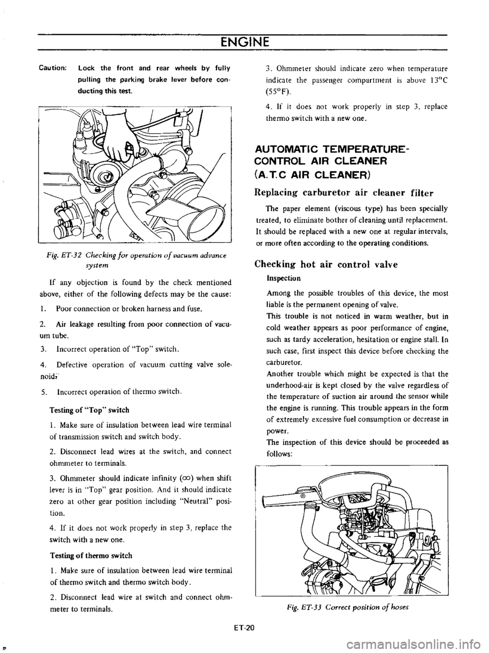
Fig
ET
32
Checking
for
operation
of
vacuum
advance
system
If
any
objection
is
found
by
the
check
mentioned
above
either
of
the
following
defects
may
be
the
cause
Poor
connection
or
broken
harness
and
fuse
2
Air
leakage
resulting
from
poor
connection
of
vacu
um
tube
3
Incorrect
operation
of
Top
switch
4
Defective
operation
of
vacuum
cutting
valve
sole
naid
5
Incorrect
operation
of
thermo
switch
Testing
of
Top
switch
1
Make
sure
of
insulation
between
lead
wire
terminal
of
transmission
switch
and
switch
body
2
Disconnect
lead
wires
at
the
switch
and
connect
ohmmeter
to
tenninals
3
Ohmmeter
should
indicate
infmity
co
when
shift
lever
is
in
Top
gear
position
And
it
should
indicate
zero
at
other
gear
position
including
Neutral
posi
tion
4
If
it
does
not
work
properly
in
step
3
replace
the
switch
with
a
new
one
Testing
of
thermo
switch
I
MaJ
e
sure
of
insulation
between
lead
wire
terminal
of
thermo
switch
and
thetmo
switch
body
2
Disconnect
lead
wire
at
switch
and
connect
ohm
meter
to
terminals
Ohmmeter
should
indicate
zero
when
temperature
indicate
the
passenger
compartment
is
above
l30C
550F
4
If
it
does
not
work
properly
in
step
3
replace
thermo
switch
with
a
new
one
AUTOMATIC
TEMPERATURE
CONTROL
AIR
CLEANER
A
T
C
AIR
CLEANER
Replacing
carburetor
air
cleaner
filter
The
paper
element
viscous
type
has
been
specially
treated
to
eliminate
bother
of
cleaning
until
replacement
It
should
be
replaced
with
a
new
one
at
regular
intervals
or
more
often
according
to
the
operating
conditions
Checking
hot
air
control
valve
Inspection
Among
the
possible
troubles
of
this
device
the
most
liable
is
the
permanent
opening
of
valve
This
trouble
is
not
noticed
in
warm
weather
but
in
cold
weather
appears
as
poor
performance
of
engine
such
as
tardy
acceleration
hesitation
or
engine
stall
In
such
case
first
inspect
this
device
before
checking
the
carburetor
Another
trouble
which
might
be
expected
is
that
the
underhood
air
is
kept
closed
by
the
valve
regardless
of
the
temperature
of
suction
air
around
the
sensor
while
the
engine
is
running
This
ttOuble
appears
in
the
form
of
extremely
excessive
fuel
consumption
or
decrease
in
power
The
inspection
of
this
device
should
be
proceeded
as
follows
Fig
ET
33
Correct
position
of
hoses
ET
20
Page 326 of 513
EMISSION
CONTROL
AND
TUNE
UP
Appearance
1
First
inspect
whether
vacuum
hoses
are
connected
to
correct
positions
2
Inspect
hoses
for
cracks
distortion
or
plugging
Checking
of
vacuum
motor
I
With
engine
shut
down
inspect
the
position
of
valve
placing
a
mirror
at
the
end
of
inlet
pipe
for
inspec
tion
The
correct
condition
of
valve
is
that
it
keeps
the
inlet
of
underhood
air
open
and
that
of
hot
air
closed
Otherwise
inspect
the
linkage
of
valve
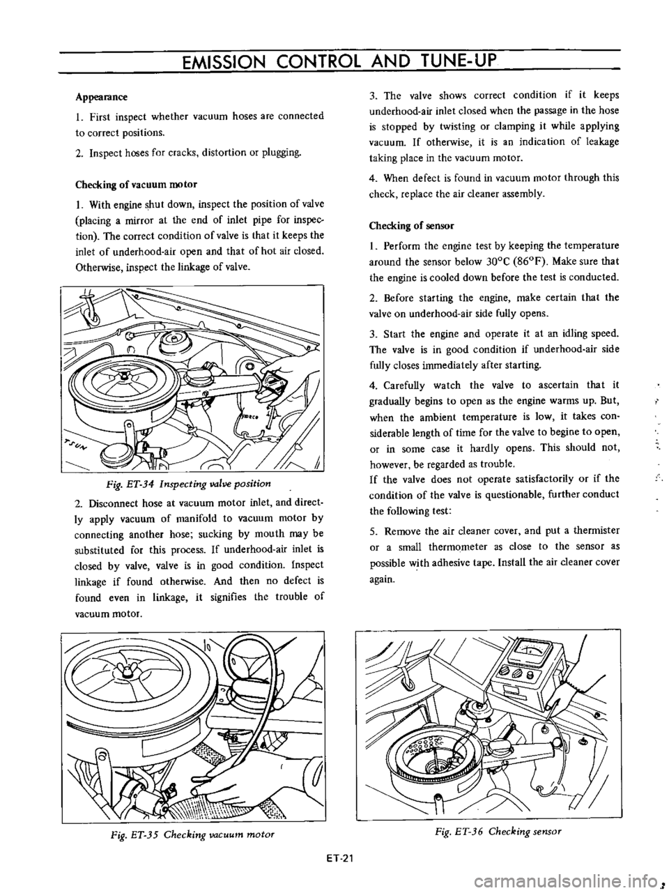
Fig
ET
34
Inspecting
valve
position
2
Disconnect
hose
at
vacuum
motor
inlet
and
direct
ly
apply
vacuum
of
manifold
to
vacuum
motor
by
connecting
another
hose
sucking
by
mouth
may
be
substituted
for
this
process
If
underhood
air
inlet
is
closed
by
valve
valve
is
in
good
condition
Inspect
linkage
if
found
otherwise
And
then
no
defect
is
found
even
in
linkage
it
signifies
the
trouble
of
vacuum
motor
Fig
ET
35
Checking
vacuum
motor
ET
21
3
The
valve
shows
correct
condition
if
it
keeps
underhood
air
inlet
closed
when
the
passage
in
the
hose
is
stopped
by
twisting
or
clamping
it
while
applying
vacuum
If
otherwise
it
is
an
indication
of
leakage
taking
place
in
the
vacuum
motor
4
When
defect
is
found
in
vacuum
motor
through
this
check
replace
the
air
cleaner
assembly
Checking
of
sensor
I
Perform
the
engine
test
by
keeping
the
temperature
around
the
sensor
below
300C
860F
Make
sure
that
the
engine
is
cooled
down
before
the
test
is
conducted
2
Before
starting
the
engine
make
certain
that
the
valve
on
underhood
air
side
fully
opens
3
Start
the
engine
and
operate
it
at
an
idling
speed
The
valve
is
in
good
condition
if
underhood
air
side
fully
closes
immediately
after
starting
4
Carefully
watch
the
valve
to
ascertain
that
it
gradually
begins
to
open
as
the
engine
warms
up
But
when
the
ambient
temperature
is
low
it
takes
con
siderable
length
of
time
for
the
valve
to
begine
to
open
or
in
some
case
it
hardly
opens
This
should
not
however
be
regarded
as
trouble
If
the
valve
does
not
operate
satisfactorily
or
if
the
condition
of
the
valve
is
questionable
further
conduct
the
following
test
5
Remove
the
air
cleaner
cover
and
put
a
thermister
or
a
small
thermometer
as
close
to
the
sensor
as
possible
with
adhesive
tape
Install
the
air
cleaner
cover
again
Fig
ET
36
Checking
sensor
1
Page 327 of 513
ENGINE
6
Start
the
engine
and
continue
idling
as
described
under
paragraphs
I
2
and
3
above
When
several
minutes
have
passed
and
the
valve
is
partially
opened
read
the
thermister
indication
It
is
correct
if
the
reading
falls
between
380C
1000
F
and
550C
1300
F
If
the
reading
is
abnormal
replace
the
sensor
7
On
the
engine
equipped
with
an
idle
compensator
as
service
option
do
as
follows
before
replacing
the
sensor
Clog
hose
on
idle
compensator
side
by
twisting
or
clamping
it
and
check
the
temperature
as
given
in
paragraphs
5
and
6
above
If
the
thermometer
shO
vs
correct
temperature
replace
the
idle
compensa
tOf
if
the
reading
is
abnormal
replace
the
sensor
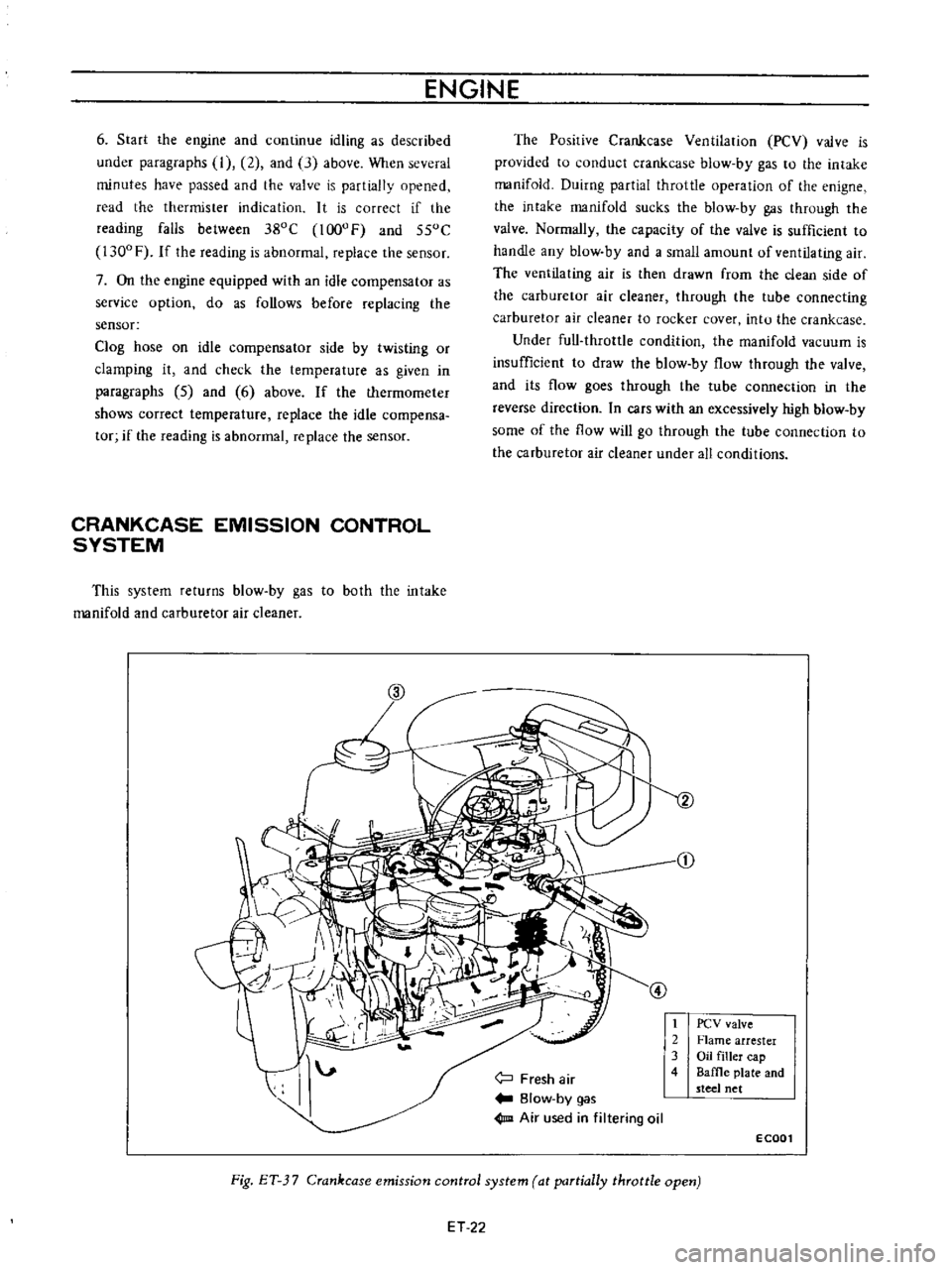
CRANKCASE
EMISSION
CONTROL
SYSTEM
This
system
returns
blow
by
gas
to
both
the
intake
manifold
and
carburetor
air
cleaner
The
Posirive
Crankcase
Ventilation
PCV
valve
is
provided
to
conduct
crankcase
blow
by
gas
to
the
intake
manifold
Duirng
partial
throttle
operation
of
the
enigne
the
intake
manifold
sucks
the
blow
by
gas
through
the
valve
Normally
the
capacity
of
the
valve
is
sufficient
to
handle
any
blow
by
and
a
small
amount
of
ventilating
air
The
ventilating
air
is
then
drawn
from
the
clean
side
of
the
carburetor
air
cleaner
through
the
tube
connecting
carburetor
air
cleaner
to
rocker
cover
intu
the
crankcase
Under
full
throttle
condition
the
manifold
vacuum
is
insufficient
to
draw
the
blow
by
flow
through
the
valve
and
its
flow
goes
through
the
tube
connection
in
the
reverse
direction
In
cars
with
an
excessively
high
blow
by
some
of
the
flow
will
go
through
the
tube
connection
to
the
carburetor
air
cleaner
under
all
conditions
j
Fresh
air
Blow
by
gas
1m
Air
used
in
filtering
oil
t
2
3
4
PCV
valve
Flame
arrester
Oil
filler
cap
Baffle
plate
and
steel
net
ECOOl
Fig
ET
3
7
Crankcase
emission
control
system
at
partially
throttle
open
ET
22