1973 DATSUN B110 suspension
[x] Cancel search: suspensionPage 86 of 513
DATSUN
1200
MODEL
B
110
SERIES
I
NISSAN
I
NISSAN
MOTOR
CO
LTD
TOKYO
JAPAN
SECTION
FA
FRONT
AXLE
FRONT
SUSPENSION
all
FRONT
AXLE
AND
FRONT
SUSPENSION
ADJUSTMENT
SERVICE
DATA
AND
SPECIFICATIONS
TROUBLE
DIAGNOSES
AND
CORRECTIONS
FA
1
FA
21
FA
23
FA
25
Page 87 of 513
FRONT
AXLE
FRONT
SUSPENSION
FRONT
AXLE
AND
FRONT
SUSPENSION
CONTENTS
DESCRIPTION
FA
2
STRUT
ASSEMBLY
FA
ll
FRONT
AXLE
AND
Disassembly
FA
12
SUSPENSION
ASSEMBLY
FA
3
Inspection
FA
14
R
emova
I
FA
3
Reassembly
FA
15
Reinstallation
FA
5
TRANSVERSE
LINK
AND
FRONT
AXLE
FA
6
LOWER
BALL
JOINT
FA
17
R
emova
I
FA
6
Removal
FA
18
Inspection
FA
7
Inspection
FA
19
Rei
nstallation
FA
lO
Reinstallation
FA
19
Wheel
bearing
adjustment
FA
lO
@
@
Fig
FA
l
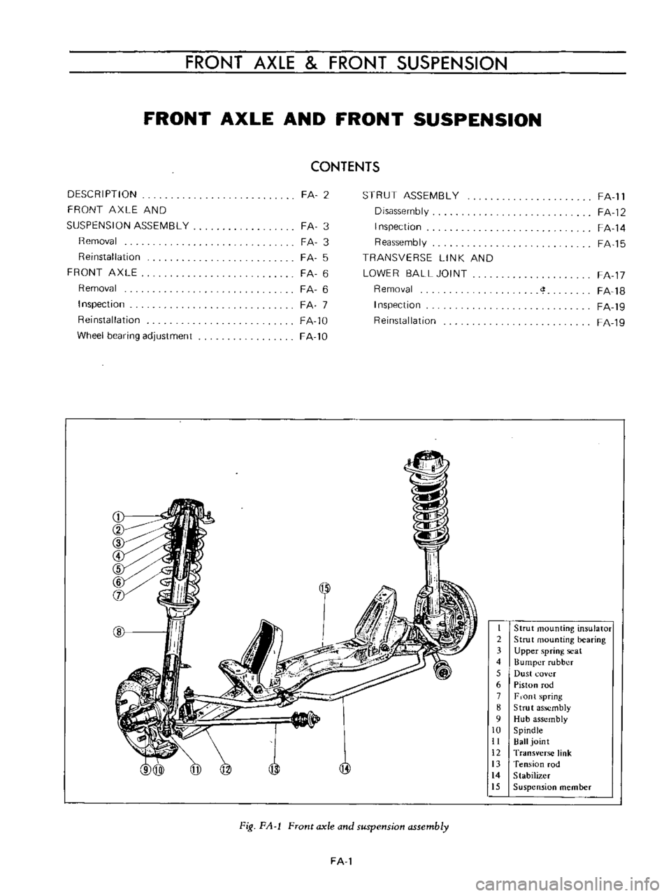
Front
axle
and
suspension
assembly
FA
l
I
Strut
mounting
insulator
2
Strut
mounting
bearing
3
Upper
spring
scal
4
Bumper
rubber
5
Dust
l
ovcr
6
Piston
rod
7
F
on
t
spring
8
Strut
assembly
9
Hub
assembly
10
Spindle
II
Ball
joint
12
Transverse
link
13
Tension
fod
14
Stabilizer
15
Suspension
member
Page 88 of 513
CHASSIS
DESCRIPTION
The
front
suspension
is
of
a
strut
lype
The
shock
absurber
and
spindle
are
combined
to
a
single
unit
which
is
supported
by
the
coil
spring
at
the
upper
end
aod
by
the
transverse
link
at
the
lower
end
The
spindle
is
ins
tailed
on
the
bottom
of
the
strut
outer
casing
by
means
of
welding
A
ball
joint
is
attached
to
the
lower
part
of
the
spindle
The
ball
joint
and
the
transverse
link
lower
link
are
connected
and
they
are
fitted
to
the
suspension
member
through
a
rubber
bushing
The
shock
absorber
mechanism
is
built
in
the
strut
outer
casing
A
coil
spring
is
applied
between
the
upper
spring
seat
filled
to
the
upper
end
of
the
piston
rod
and
spring
seat
welded
to
the
outer
casing
These
components
assembled
to
a
single
unit
are
fitted
tu
the
chassis
frame
at
their
upper
part
through
the
thrust
bearing
Moreover
the
transverse
link
supports
the
overall
forward
and
backward
strut
movements
by
means
of
the
tension
rod
filled
to
the
chassis
frame
through
a
rubber
bushing
The
rubber
bushing
adopts
a
non
linear
shape
with
which
the
forward
and
rearward
rigidities
are
changed
The
torsion
bar
type
stabilizer
adopted
in
this
suspension
system
is
used
so
that
the
strut
maintains
connection
between
both
side
struts
Thus
this
suspension
mechanism
absorbs
shocks
toward
all
directions
into
the
chassis
effectively
and
efficiently
the
tension
rod
absorbs
forward
and
backward
shocks
the
strut
absorbs
vertical
shock
and
the
transverse
link
absorbs
shock
applied
toward
sideway
t
J
f
II
L
II
I
7
f
1
I
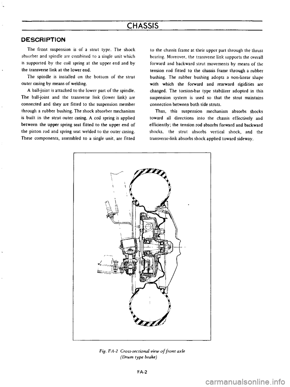
Fig
F
1
2
Cross
sectional
view
of
front
axle
Drum
type
brake
FA
2
Page 89 of 513
FRONT
AXLE
FRONT
SUSPENSION
FRONT
AXLE
AND
SUSPENSION
ASSEMBLY
Removal
1
Jack
up
the
vehicle
and
support
the
vehicle
with
stands
See
the
Section
GL
2
Remove
the
hub
nuts
and
remOve
the
wheel
3
Remove
the
splash
board
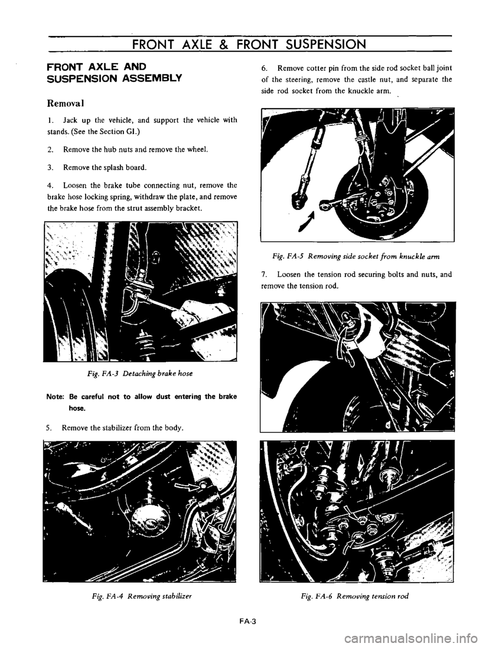
4
Loosen
the
brake
tube
connecting
nut
remove
the
brake
hose
locking
spring
withdraw
the
plate
and
remOve
the
brake
hose
from
the
strul
assembly
bracket
Fig
FA
3
Detaching
brake
hose
Note
Be
careful
not
to
allow
dust
entering
the
brake
hose
5
Remove
the
stabilizer
from
the
body
Fig
FA
4
Removing
stabilizer
6
Remove
cotter
pin
from
the
side
rod
socket
ball
joint
of
the
steering
remove
the
castle
nut
and
separate
the
side
rod
socket
from
the
knuckle
arm
Fig
F
A
5
Removing
side
socket
from
knuckle
arm
7
Loosen
the
tension
rod
securing
bolts
and
nuts
and
remove
the
tension
rod
Fig
F
A
6
RemotJing
tension
rod
FA
3
Page 90 of 513
CHASSIS
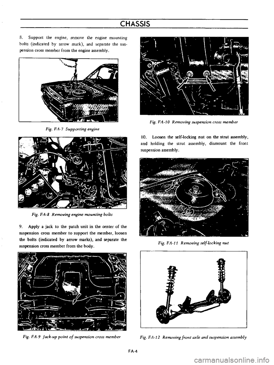
8
Support
the
engine
remove
the
engine
mounting
bolts
indicated
by
arrow
mark
and
separate
the
sus
pension
cross
member
from
the
engine
assembly
Ij
i
1
C
w
ii
lJ
c
l
I
N
r
1
a
n
h
JI
Fig
FA
7
Supporting
engine
I
IV
U
II
G
11J
r
j
F
l
I
IV
I
iL
I
0
I
l
tt
I
i
L
I
It
v
i
1
0
b
c
Ii
irti
J
I
I
1
1
Zi
J
l
ll
c
h
f
J
f
C
Fig
FA
8
Removing
engine
mounting
bolts
9
Apply
a
jack
to
the
patch
unit
in
the
center
of
the
suspension
cross
member
to
support
the
member
loosen
the
bolts
indicated
by
arrow
marks
and
separate
the
suspension
cross
member
from
the
body
Fig
FA
9
Jack
up
point
of
suspension
cross
member
Fig
FA
10
Removing
suspension
cross
member
10
Loosen
the
self
locking
nut
on
the
strut
assembly
and
holding
the
strut
assembly
dismount
the
front
suspension
assembly
Fig
F
1
11
Removing
s
flocking
nut
Fig
F
A
12
Removing
front
axle
and
suspension
assembly
FAA
Page 91 of 513
FRONT
AXLE
FRONT
SUSPENSION
Reinstalla
tion
First
check
rubber
parts
such
as
tension
rod
mount
ing
bushing
stabilizer
bar
bushing
etc
for
deterioration
crack
and
other
defective
conditions
and
replace
as
required
2
Reinstall
the
front
axle
and
suspension
assembly
in
reverse
sequence
of
removal
noting
the
following
matters
1
Tighten
the
transverse
link
mounting
bolts
and
stabilizer
bar
body
side
installation
bolt
to
the
raled
tightening
torque
under
the
unladen
vehicle
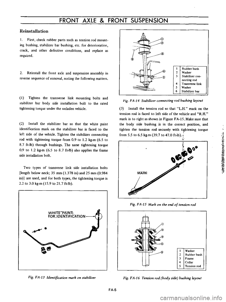
2
Install
the
stabilizer
bar
so
that
the
white
paint
identification
mark
on
the
stabilizer
bar
is
faced
to
the
left
side
of
the
vehicle
Tighten
the
stabilizer
connecting
rod
with
tightening
torque
from
0
9
to
1
2
kg
m
6
5
to
8
7
ft
lb
through
bushings
The
same
tightening
torque
0
9
to
1
2
kg
m
6
5
to
8
7
ft
Ib
also
applies
the
frame
side
installation
bolt
Two
types
of
transverse
link
side
installation
bolts
length
below
neck
35
mm
1
378
in
and
25
mm
0
984
in
are
used
and
for
both
types
the
tightening
torque
is
2
2
to
3
0
kg
m
15
9
to
217
ft
lb
WH
ITFPAI
Nli
F
OR
IDENjIFICATION
H
Fig
FA
13
Identification
mark
on
stabilizer
I
J
1
Rubber
hush
2
Washer
3
Stabilizer
con
necting
rod
4
Transverse
link
5
Washer
6
Stabilizer
bar
Fig
FA
14
Stabilizer
connecting
rod
bushing
layout
3
Install
the
tension
rod
so
that
LH
mark
on
the
tension
rod
is
faced
to
left
side
of
the
vehicle
and
R
H
mark
is
to
right
as
shown
in
Figure
FA
IS
Make
sure
that
the
body
side
bushing
is
in
the
correct
position
and
tighten
the
tension
rod
securely
with
tightening
torque
from
5
5
to
6
5
kg
m
39
7
to
47
0
ft
lb
ii
j
iY
l
fj
i
f
i
Of
1
0
Fig
FA
15
Mark
on
the
end
of
tension
rod
il
1
Washer
2
Rubber
bush
3
Frame
4
Collar
5
Tension
rod
Fig
FA
16
Tension
rod
body
side
bushing
layout
FA
5
Page 92 of 513

CHASSIS
Tightening
torque
of
front
suspension
cross
member
and
body
is
3
2
to
4
0
kg
m
23
1
to
28
9
ft
Ib
5
Tightening
torque
of
bolt
used
to
secure
the
upper
portion
of
the
strut
assembly
on
the
body
is
1
6
to
2
1
kg
m
11
6
to
15
2ft
lb
FRONT
AXLE
Removal
I
Jack
up
the
vehicle
remove
the
wheel
and
discon
nect
the
brake
hose
at
the
strut
outer
casing
bracket
unit
For
details
see
Removal
of
front
axle
and
suspension
assembly
2
Remove
the
brake
caliper
installation
bolts
and
remove
the
caliper
assembly
Disc
type
brake
3
Remove
the
brake
druOL
Drum
type
brake
4
Remove
the
hub
cap
with
a
flal
headed
screwdriver
or
other
proper
tool
and
hammer
Be
sure
to
tap
lightly
5
Remove
cotter
pin
from
the
wheel
bearing
lock
nut
and
remove
the
lock
nut
6
With
the
wheel
bearing
washer
and
wheel
bearing
installed
on
the
wheel
hub
remove
the
wheel
hub
from
the
spindle
In
the
case
of
a
disc
type
brake
the
wheel
hub
may
be
removed
with
the
disc
rotor
installed
on
the
wheel
hub
Fig
FA
17
Removing
wheel
hub
7
Remove
the
return
spring
and
brake
shoes
remove
brake
disc
assembly
installation
bolts
and
remove
the
brake
disc
assembly
from
the
spindle
Drum
type
brake
Fig
FA
IS
Removing
brake
disc
a
ssembly
8
Remove
baffle
plate
set
screws
and
remove
the
baffle
plate
Disc
type
brake
Fig
FA
19
Removingbaffleplate
9
Utilizing
two
grooves
inside
the
wheel
hub
tap
and
remove
the
wheel
bearing
outer
race
from
the
hub
Fig
FA
20
Removing
wheel
bearing
outer
race
FA
6
Page 93 of 513

FRONT
AXLE
FRONT
SUSPENSION
10
Remove
four
brake
disc
fitting
bolts
and
remove
the
brake
disc
rotor
from
the
wheel
hub
assembly
Disc
type
b
rake
Inspection
1
Grease
seal
I
ycQ
r
A
1
r
j
t
I
I
i
I
When
grease
leakage
is
delected
during
disassembly
replace
2
Replace
the
grease
seal
with
a
new
one
if
worn
or
cracked
Fig
FA
21
Removing
brake
disc
rotor
2
Wheel
bearing
Remove
used
grease
from
the
wheel
bearing
with
solvent
and
inspect
the
bearing
for
operating
condition
from
the
rotation
operating
sound
and
appearance
The
outer
race
may
be
checked
for
the
condition
of
rolling
surface
with
the
race
installed
on
the
wheel
hub
Visual
serviceability
judgement
standard
for
the
wheel
bearing
is
indicated
in
the
following
table
Visual
Serviceability
Judg
ment
Standard
for
Wheel
Bearing
INNER
RACE
SURFACE
OUTER
RACE
FITTED
SURFACE
COLLAR
SURFACE
OUTER
RACE
SURFACE
INNER
RACE
FITTED
ROLLER
ROLLING
SURFACE
SURFACE
SMALL
COLLAR
INNER
RACE
LARGE
COLLAR
ROLLER
SUPPORTER
OUTER
RACE
FA
7