1973 DATSUN B110 suspension
[x] Cancel search: suspensionPage 106 of 513
CHASSIS
ST36721000
ST36722000
I
ST36723000
r
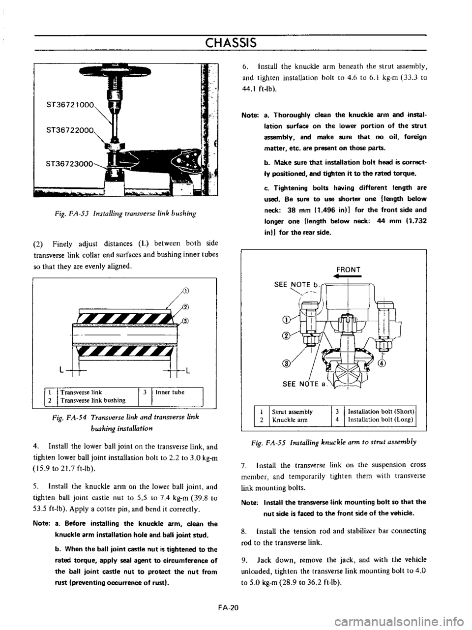
Fig
FA
53
Installing
transverse
link
bushing
2
Finely
adjust
distances
L
between
both
side
transverse
link
collar
end
surfaces
and
bushing
inner
tubes
so
that
they
are
evenly
aligned
D
r
Ii
l
Ii
3
F
f
IIII
I
I
L
T
L
It
I
Transverse
link
2
Transverse
link
bushing
I
3
I
Inner
tube
Fig
FA
54
Transverse
link
and
transverse
link
bushing
nstal1o
tion
4
Install
the
lower
ball
joint
on
the
transverse
link
and
tighten
lower
ball
joint
installation
bolt
to
2
2
to
3
0
kg
m
159
to
21
7
ft
Ib
5
Install
the
knuckle
arm
on
the
lower
ball
joint
and
tighten
ball
joint
castle
nut
to
5
5
to
74
kg
m
39
8
to
53
5
ft
Ib
Apply
a
cotter
pin
and
bend
it
correctly
Note
3
Before
installing
the
knuckle
arm
clean
the
knuckle
arm
installation
hole
and
ball
joint
stud
b
When
the
ball
joint
castle
nut
is
tightened
to
the
rated
torque
apply
seal
agent
to
circumference
of
the
ball
joint
castle
nut
to
protect
the
nut
from
rust
preventing
occurrence
of
rust
FA
20
6
InstaIJ
the
knuckle
arm
beneath
the
strut
assembly
and
tighten
instaIJation
bolt
to
4
6
to
6
J
kg
m
33
3
to
44
I
ft
lb
Note
a
Thoroughly
clean
the
knuckle
arm
and
instal
lation
surface
on
the
lower
portion
of
the
strut
assembly
and
make
sure
that
no
oil
foreign
maner
etc
are
present
on
those
parts
b
Make
sure
that
installation
bolt
head
is
correct
ly
positioned
and
tighten
it
to
the
rated
torque
c
Tightening
bolu
having
different
length
are
used
Be
sure
to
use
shorter
one
length
below
neck
38
mm
11496
in
for
the
front
side
and
longer
one
length
below
neck
44
mm
1
132
in
for
the
rear
side
FRONT
II
I
Strut
assembly
2
Knuckle
arm
143
I
Installation
bolt
Short
I
Installation
bolt
Long
Fig
FA
55
Installing
knuckle
ann
to
strut
assembly
7
I
nstall
the
transverse
link
on
the
suspension
cross
member
and
temporarily
tighten
them
with
transverse
link
mounting
bolts
Note
Install
the
transverse
link
mounting
bolt
so
that
the
nut
side
is
faced
to
the
front
side
of
the
vehicle
8
Install
the
tension
rod
and
stabilizer
bar
connecting
rod
to
the
transverse
link
9
Jack
down
remove
the
jack
and
with
the
vehicle
unloaded
tighten
the
transverse
link
mounting
bolt
to
4
0
to
5
0
kg
m
28
9
to
36
2
ft
lb
Page 107 of 513
FRONT
AXLE
FRONT
SUSPENSION
ADJUSTMENT
CONTENTS
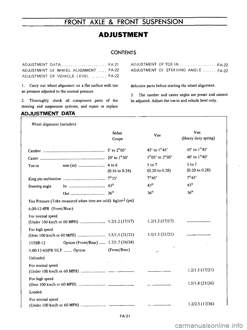
ADJUSTMENT
DATA
ADJUSTMENT
OF
WHEEL
ALIGNMENT
ADJUSTMENT
OF
VEHICLE
LEVEL
FA
21
FA
22
FA
22
1
Carry
out
wheel
alignment
on
a
flat
surface
with
tire
air
pressure
adjusted
to
the
normal
pressure
2
Thoroughly
check
all
component
parts
of
the
steering
and
suspension
systems
and
repair
or
replace
AD
JUSTMENT
DATA
I
Wheel
alignment
unladen
Sedan
Coupe
Camber
5
to
2005
Caster
20
to
1050
Toe
in
mm
in
4
to
6
0
16
to
0
24
King
pin
inclination
7055
Steering
angle
In
430
Out
360
Tire
Pressure
Tobe
measured
when
tires
are
cold
kgfcm2
psi
6
00
12
4PR
Front
Rear
For
normal
speed
Under
100
km
h
or
60
MPH
For
high
speed
Over
100
km
h
or
60
MPH
15SSR
12
Option
Front
Rear
1
2
1
2
17
17
1
5
1
5
21
21
I
7
I
7
24
24
Front
Rear
5
00
12
4
6
R
ULT
Unloaded
Option
For
normal
speed
Under
100
km
h
or
60
MPH
For
high
speed
Over
100
km
h
or
60
MPH
Loaded
For
normal
speed
Under
100
km
h
or
60
MPH
FA
21
ADJUSTMENT
OF
TOE
IN
ADJUSTMENT
OF
STEERING
ANGLE
FA
22
FA
22
defective
parts
before
starting
the
wheel
alignment
3
The
camber
and
caster
angles
are
preset
and
cannot
be
adjusted
Adjust
the
toe
in
and
vehicle
level
only
Van
Van
Heavy
duty
spring
45
to
1045
45
to
1045
1005
to
2005
40
to
1040
5
to
7
5
to
7
0
20
to
0
28
0
20
to
0
28
7045
7045
430
430
360
360
1
2
1
2
I
7
I
7
1
5
1
5
21
21
1
2
1
5
17
21
1
5
1
8
21
26
1
2
2
5
17
36
Page 109 of 513
FRONT
AXLE
FRONT
SUSPENSION
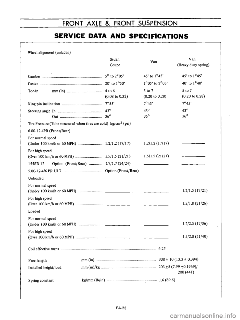
SERVICE
DATA
AND
SPECIFICATIONS
Wheel
alignment
unladen
Sedan
Van
Van
Coupe
Heavy
duty
spring
Camber
50
to
2005
45
to
1
45
45
to
1045
Caster
20
to
1050
r005
to
2005
40
to
1040
Toe
in
mm
in
4
t06
5
to
7
5
to
7
0
08
to
032
0
20
to
0
28
0
20
to
0
28
King
pin
inclination
7055
7045
7045
Steering
angle
In
430
430
430
Out
360
360
360
Tire
Pressure
Tobe
measured
when
tires
are
cold
kg
cm2
psi
6
00
12
4PR
Front
Rear
For
normal
speed
Under
100
km
h
or
60
MPH
1
2
1
2
17
17
1
2
1
2
17
17
For
high
speed
Over
100
km
h
or
60
MPH
155SR
12
Option
Front
Rear
5
00
12
4
6
PR
ULT
Unloaded
1
5
1
5
21
21
1
7
1
7
24
24
Option
Front
Rear
1
5
1
5
21
21
For
normal
speed
Under
100
km
h
or
60
MPH
For
high
speed
Over
100
km
h
or
60
MPH
Loaded
1
2
1
5
17
21
1
5
1
8
21
26
For
normal
speed
Under
100
km
h
or
60
MPH
For
high
speed
Over
100
km
h
or
60
MPH
1
2
2
5
17
36
1
5
2
8
21
40
Coil
effective
turns
6
25
Free
length
Installed
height
load
mm
in
mm
in
kg
338
i
10
133
0394
203i5
7
99
iO
1969
200
441
Spring
constan
t
kgfmm
lb
in
1
6
89
6
FA
23
Page 111 of 513
FRONT
AXLE
FRONT
SUSPENSION
joint
Transverse
link
mounting
bolt
Tension
rod
Transverse
link
side
Body
side
Stabilizer
bar
Connecting
rod
and
transverse
link
installation
nut
Connecting
rod
and
stabilizer
bar
installation
nut
Stabilizer
bar
and
body
installation
bolt
2
2
to
3
0
15
9
to
21
7
4
0
to
5
0
28
9
to
36
2
2
2
to
3
0
15
9
to
217
5
5
to
6
5
39
7
to
47
0
0
9
to
1
2
6
5
to
8
7
0
9
to
1
2
6
5
to
8
7
0
9
to
1
2
6
5
to
8
7
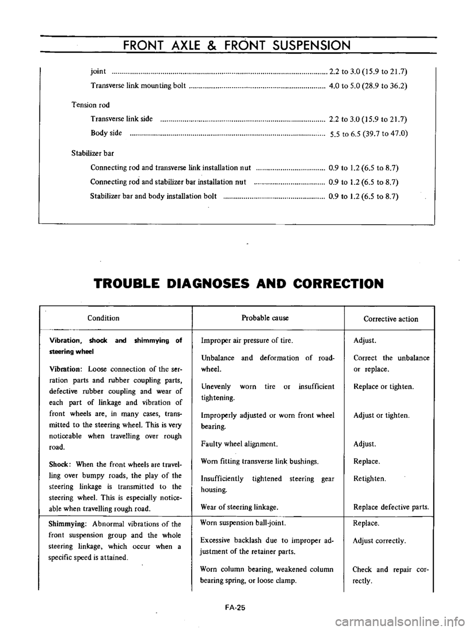
TROUBLE
DIAGNOSES
AND
CORRECTION
Condition
Vibration
shock
and
shimmying
of
steering
wheel
Vibmtion
Loose
connection
of
the
ser
ration
parts
and
rubber
coupling
parts
defective
rubber
coupling
and
wear
of
each
part
of
linkage
and
vibration
of
front
wheels
are
in
many
cases
trans
mitted
to
the
steering
wheeL
This
is
very
noticeable
when
travelling
over
rough
road
Shock
When
the
front
wheels
are
travel
ling
over
bumpy
roads
the
play
of
the
steering
linkage
is
transmitted
to
the
steering
wheeL
This
is
especially
notice
able
when
travelling
rough
road
Shimmying
Abnormal
vibrations
of
the
front
suspension
group
and
the
whole
steering
linkage
which
occur
when
a
specific
speed
is
attained
Probable
cause
Improper
air
pressure
of
tire
Unbalance
and
deformation
of
road
wheeL
Unevenly
worn
tire
or
insufficient
tightening
Improperly
adjusted
or
worn
front
wheel
bearing
Faulty
wheel
alignment
Worn
fitting
transverse
link
bushings
Insufficiently
tightened
steering
gear
housing
Wear
of
steering
linkage
Worn
suspension
ball
joint
Excessive
backlash
due
to
improper
ad
justment
of
the
retainer
parts
Worn
column
bearing
weakened
column
bearing
spring
or
loose
clamp
FA
25
Corrective
action
Adjust
Correct
the
unbalance
or
replace
Replace
or
tighten
Adjust
or
tighten
Adjust
Replace
Retighten
Replace
defective
parts
Replace
Adjust
correctly
Check
and
repair
cor
rectly
Page 112 of 513
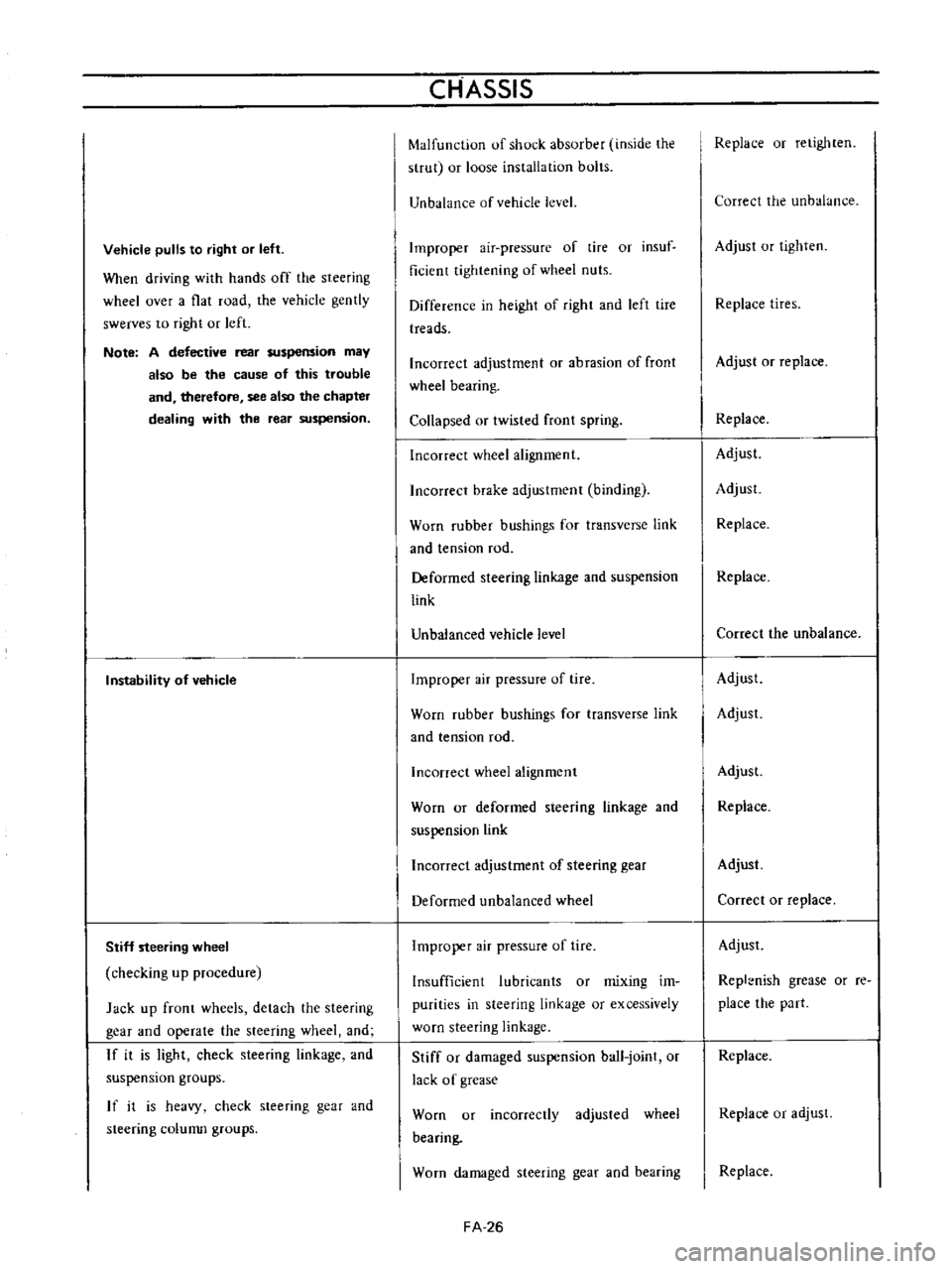
Vehicle
pulls
to
right
or
left
When
driving
with
hands
off
the
steering
wheel
over
a
flat
road
the
vehicle
gently
swerves
to
right
or
left
Note
A
defective
rear
suspension
may
also
be
the
cause
of
this
trouble
and
therefore
see
also
the
chapter
dealing
with
the
rear
suspension
Instability
of
vehicle
Stiff
steering
wheel
checking
up
procedure
Jack
up
front
wheels
detach
the
steering
gear
and
operate
the
steering
wheel
and
If
it
is
light
check
steering
linkage
and
suspension
groups
If
it
is
heavy
check
steering
gear
and
steering
colunm
groups
CHASSIS
Malfunction
of
shock
absorber
inside
the
strut
or
loose
installation
bolts
Unbalance
of
vehicle
level
Improper
air
pressure
of
tire
or
insuf
ficient
tightening
of
wheel
nuts
Difference
in
height
of
right
and
left
tire
treads
Incorrect
adjustment
or
abrasion
of
front
wheel
bearing
Collapsed
or
twisted
front
spring
Incorrect
wheel
alignment
Incorrect
brake
adjustment
binding
Worn
rubber
bushings
for
transverse
link
and
tension
rod
Deformed
steering
linkage
and
suspension
link
Unbalanced
vehicle
level
Improper
air
pressure
of
tire
Worn
rubber
bushings
for
transverse
link
and
tension
rod
Incorrect
wheel
alignment
Worn
or
deformed
steering
linkage
and
suspension
link
Incorrect
adjustment
of
steering
gear
Deformed
unbalanced
wheel
Improper
air
pressure
of
tire
Insufficient
lubricants
or
mixing
im
purities
in
steering
linkage
or
excessively
worn
steering
linkage
Stiff
or
damaged
suspension
ball
joint
or
lack
of
grease
Worn
or
incorrectly
adjusted
wheel
bearing
Worn
damaged
steering
gear
and
bearing
FA
26
Replace
or
retighten
Correct
the
unbalance
Adjust
or
tighten
Replace
tires
Adjust
or
replace
Replace
Adjust
Adjust
Replace
Replace
Correct
the
unbalance
Adjust
Adjust
Adjust
Replace
Adjust
Correct
or
replace
Adjust
Repl
nish
grease
or
re
place
the
part
Replace
Replace
or
adjust
Replace
Page 113 of 513
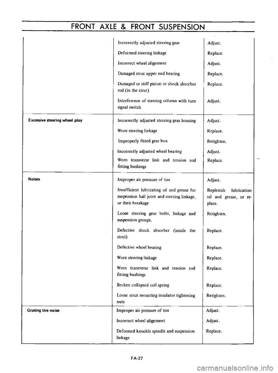
FRONT
AXLE
FRONT
SUSPENSION
Incorrectly
adjusted
steering
gear
Deformed
steering
linkage
Incorrect
wheel
alignment
Damaged
strut
upper
end
bearing
Damaged
or
stiff
piston
or
shock
absorber
rod
in
the
strut
Interference
of
steering
column
with
turn
signal
switch
Excessive
steering
wheel
play
Noises
Grating
tire
noise
Incorrectly
adjusted
steering
gear
housing
Worn
steering
linkage
Improperly
fitted
gear
box
Incorrectly
adjusted
wheel
bearing
Worn
transverse
link
and
tension
rod
fitting
bushings
Improper
air
pressure
of
tire
Insufficient
lubricating
oil
and
grease
for
suspension
ball
joint
and
steering
linkage
or
their
breakage
Loose
steering
gear
bolts
linkage
and
suspension
groups
Defective
shock
absorber
inside
the
strut
Defective
wheel
bearing
Worn
steering
linkage
Worn
transverse
link
and
tension
rod
fitting
bushings
Broken
collapsed
coil
spring
Loose
strut
mounting
insulator
tightening
nuts
Improper
air
pressure
of
tire
Incorrect
wheel
alignment
Deformed
knuckle
spindle
and
suspension
linkage
FA
27
Adjust
Replace
Adjust
Replace
Replace
Adjust
Adjust
Replace
Retighlen
Adjust
Replace
Adjust
Replenish
lubrication
oil
and
grease
or
re
place
Retighten
Replace
Replace
Replace
Replace
Replace
Retighten
Adjust
Adjust
Replace
Page 115 of 513
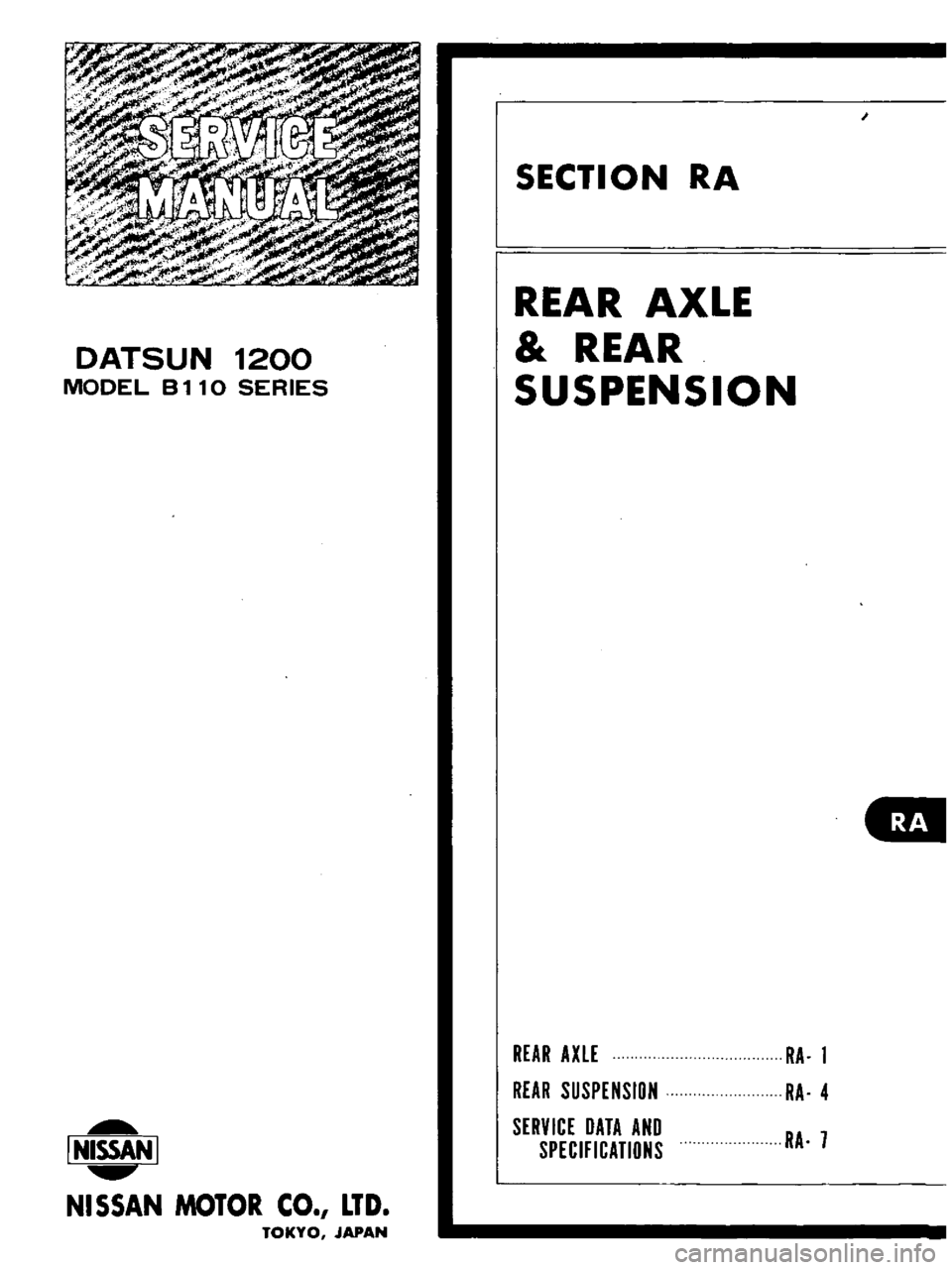
DATSUN
1200
MODEL
B
1
10
SERIES
I
NISSAN
I
NISSAN
MOTOR
CO
LTD
TOKYO
JAPAN
SECTION
RA
REAR
AXLE
REAR
SUSPENSION
REAR
AXLE
REAR
SUSPENSION
SERVICE
DATA
AND
SPECIFICATIONS
RA
1
RA
4
RA
7
Page 116 of 513
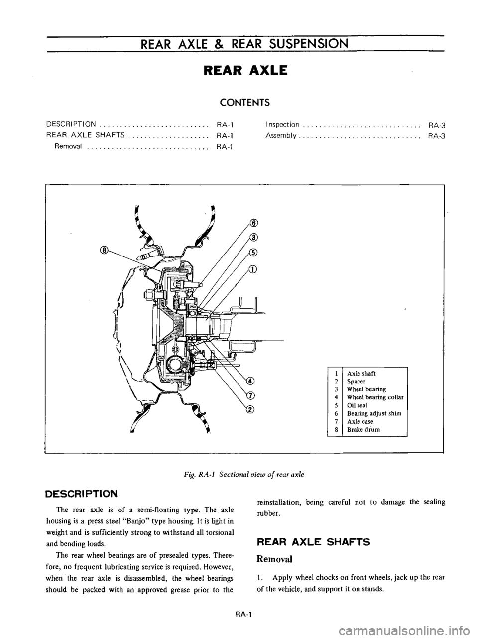
REAR
AXLE
REAR
SUSPENSION
REAR
AXLE
CONTENTS
DESCRIPTION
REAR
AXLE
SHAFTS
Removal
RA
1
RA
l
RA
l
8
Inspection
Assembly
RA
3
RA
3
1
Axle
shaft
2
Spacer
3
Wheel
bearing
4
Wheel
bearing
collar
5
Oil
seal
6
Bearing
adjust
shim
7
Axle
case
8
Brake
drum
DESCRIPTION
Fig
RA
l
Sectional
view
of
rear
axle
The
rear
axle
is
of
a
semi
floating
type
The
axle
housing
is
a
press
steel
Banjo
type
housing
It
is
light
in
weight
and
is
sufficiently
strong
to
withstand
all
torsional
and
bending
loads
The
rear
wheel
bearings
are
of
presea1ed
types
There
fore
no
frequent
lubricating
service
is
required
However
when
the
rear
axle
is
disassembled
the
wheel
bearings
should
be
packed
with
an
approved
grease
prior
io
the
reinstallation
being
careful
not
to
damage
the
sealing
rubber
REAR
AXLE
SHAFTS
Removal
Apply
wheel
chocks
on
front
wheels
jack
up
the
rear
of
the
vehicle
and
support
it
on
stands
RA
l