1973 DATSUN B110 suspension
[x] Cancel search: suspensionPage 118 of 513
REAR
AXLE
REAR
SUSPENSION
y
Jo
r
J
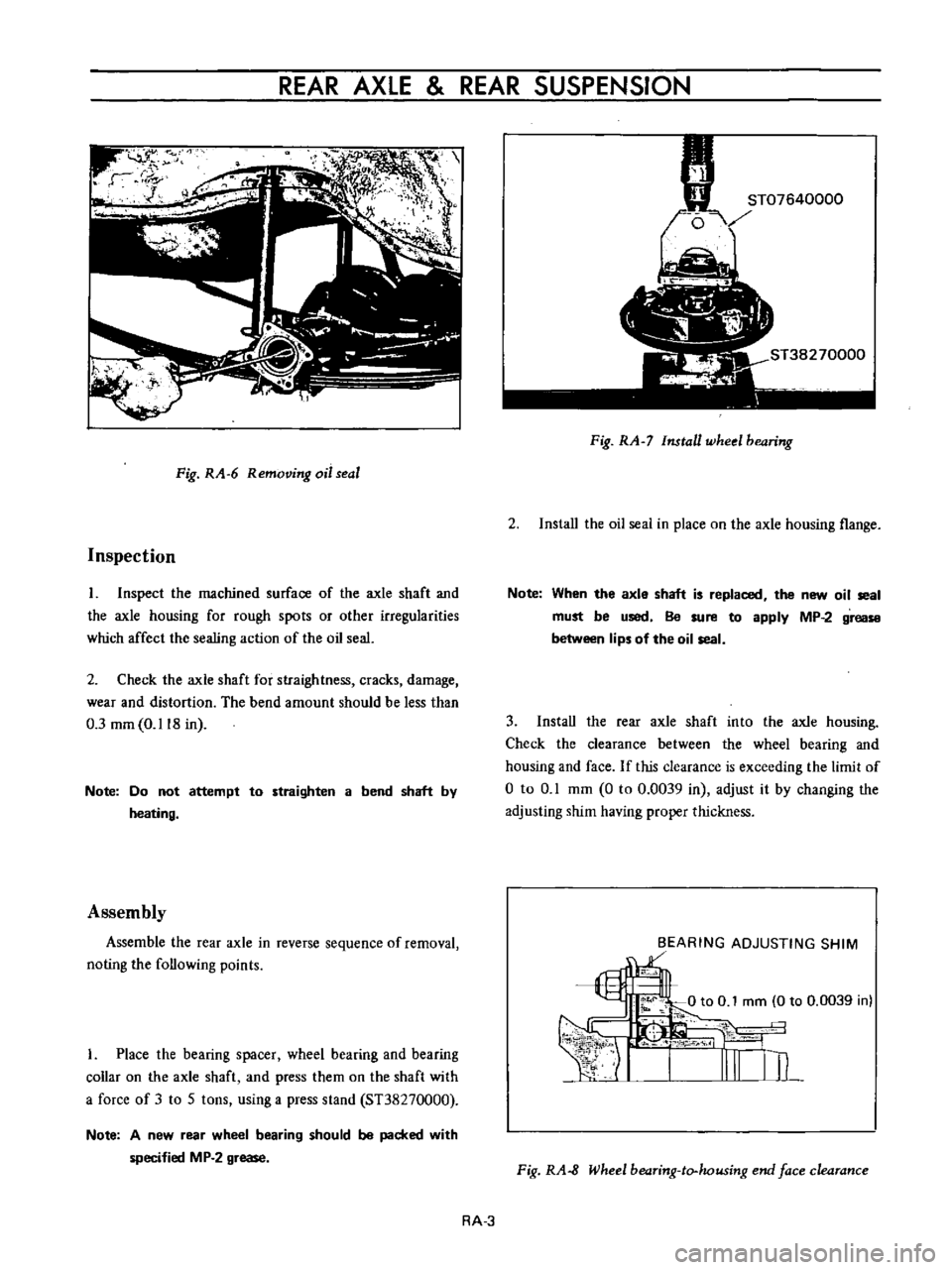
Fig
RA
6
Removing
oil
seal
Inspection
I
Inspect
the
machined
surface
of
the
axle
shaft
and
the
axle
housing
for
rough
spots
or
other
irregularities
which
affect
the
sealing
action
of
the
oil
seal
2
Check
the
axle
shaft
for
straightness
cracks
damage
wear
and
distortion
The
bend
amount
should
be
less
than
0
3
mm
0
118
in
Note
Do
not
attempt
to
straighten
a
bend
shaft
by
heating
Assembly
Assemble
the
rear
axle
in
reverse
sequence
of
removal
noting
the
following
points
I
Place
the
bearing
spacer
wheel
bearing
and
bearing
collar
on
the
axle
shaft
and
press
them
on
the
shaft
with
a
force
of
3
to
5
tons
using
a
press
stand
ST38270000
Note
A
new
rear
wheel
bearing
should
be
packed
with
specified
MP
2
grease
Fig
RA
7
Install
wheel
bearing
2
Install
the
oil
seai
in
place
on
the
axle
housing
flange
Note
When
the
axle
shaft
is
replaced
the
new
oil
seal
must
be
used
Be
sure
to
apply
MP
2
grease
between
lips
of
the
oil
seal
3
Install
the
rear
axle
shaft
into
the
axle
housing
Check
the
clearance
between
the
wheel
bearing
and
housing
and
face
If
this
clearance
is
exceeding
the
limit
of
o
to
0
1
mm
0
to
0
0039
in
adjust
it
by
changing
the
adjusting
shim
having
proper
thickness
BEARING
ADJUSTING
SHIM
1
Fig
RA
8
Wheel
bearing
to
housing
end
face
clearance
RA
3
Page 119 of 513
CHASSIS
4
Tighten
he
brake
back
plate
to
housing
nunge
bults
and
nuts
with
a
torque
of
1
5
to
2
0
kg
m
10
8
to
145
ft
Ibl
Check
the
rear
axle
shaft
end
playas
shown
in
Figure
RA
9
The
end
plav
should
be
less
than
U
I
nun
0
0039
in
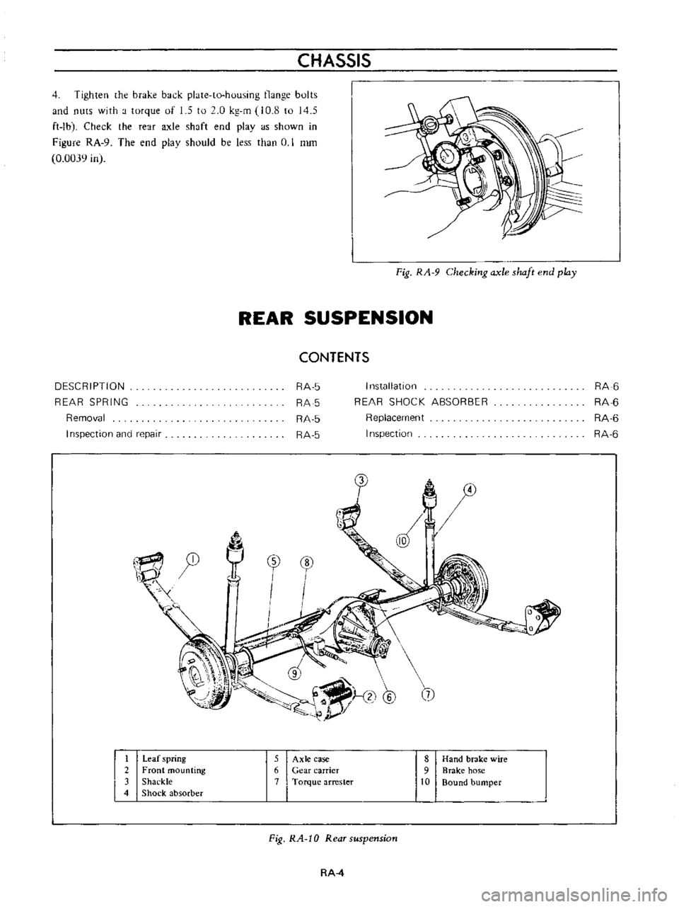
Fig
RA
9
Checking
axle
shaft
end
play
REAR
SUSPENSION
CONTENTS
DESCRIPTION
REAR
SPRING
Removal
I
nspection
and
repair
RA
5
RA
5
RA
5
RA
5
I
n5tallatlon
REAR
SHOCK
ABSORBER
Replacement
Inspection
RA
6
RA
6
RA
6
RA
6
0
tr
1
1
@
5
@
7
I
Leaf
spring
5
Axle
case
8
Hand
brake
wire
2
Front
mounting
6
Gear
carrier
9
Brake
hose
3
Shackle
7
Torque
arrester
10
Bound
bumper
4
Shock
absorber
Fig
RA
10
Rear
suspension
RA
4
Page 120 of 513
REAR
AXLE
REAR
SUSPENSION
DESCRIPTION
Rear
suspension
consists
of
semi
elliptic
leaf
springs
telescopic
hydraulic
shock
absorbers
and
rubber
bumpers
The
rear
spring
center
pin
is
off
set
110
mm
4
33
in
toward
the
front
from
the
center
of
the
spring
This
is
done
to
reduce
spring
wind
up
and
to
decrease
the
arc
while
the
rear
wheel
swings
through
Thereby
minimizing
the
possibility
of
the
rear
suspension
effecting
vehicle
stability
Iso
clamp
devices
are
used
for
attaching
the
axle
housing
to
the
spring
The
leaf
springs
shock
absorbers
and
rear
axle
housing
are
mounted
on
rubber
bushings
at
each
end
to
minimize
noise
and
vibration
of
the
transmission
to
the
car
body
and
passenger
compartment
REAR
SPRING
Removal
1
Jack
up
the
center
of
the
rear
axle
until
the
wheels
are
clear
from
the
ground
Support
the
rear
end
of
the
frame
on
stands
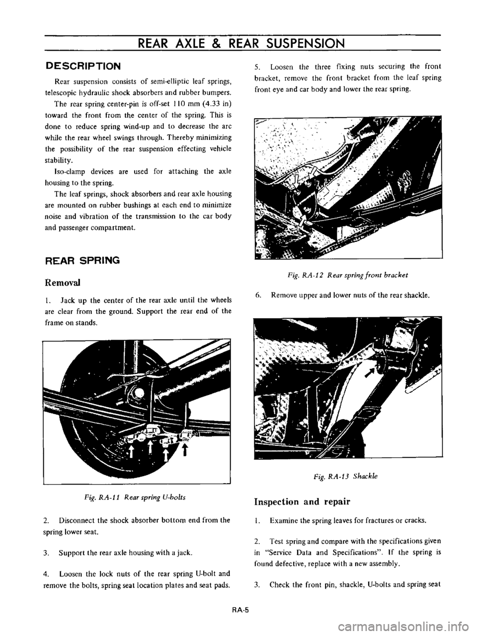
Fig
RA
l1
Rear
spring
U
bo
ts
2
Disconnect
the
shock
absorber
bottom
end
from
the
spring
lower
seat
3
Support
the
rear
axle
housing
with
a
jack
4
Loosen
the
lock
nuts
of
the
rear
spring
U
bolt
and
remove
the
bolts
spring
seat
location
plates
and
seat
pads
5
Loosen
the
three
fixing
nuts
securing
the
front
bracket
remove
the
front
bracket
from
the
leaf
spring
front
eye
and
car
body
and
lower
the
rear
spring
Fig
RA
12
Rear
spring
front
bracket
6
Remove
upper
and
lower
nuts
of
the
rear
shackle
Fig
RA
13
Shackle
Inspection
and
repair
1
Examine
the
spring
leaves
for
fractures
or
cracks
2
Test
spring
and
compare
with
the
specifications
given
in
Service
Data
and
Specifications
If
the
spring
is
found
defective
replace
with
a
new
assembly
3
Check
the
front
pin
shackle
U
bolts
and
spring
seat
RA
5
Page 122 of 513
REAR
AXLE
REAR
SUSPENSION
SERVICE
DATA
AN
D
SPECIFICATIONS
Shock
absorber
Applied
model
Sedan
Coupe
Van
Stroke
x
max
length
mm
in
167x506
6
57xI9
9
180
x
440
7
09
x
17
3
180
x
468
7
09
x
18
4
Damping
force
at
0
3mjs
Rebound
Compression
kg
Ib
kg
lb
58
128
38
83
8
68
I
50
45
99
2
90
198
45
99
2
Rear
spring
Length
x
widlh
x
thickness
NO
ofleaves
mm
in
6
I
1
llOx50x72
O
6
1
I
ll
x50x7
2
6
3
1
110
x
50
x
13
1
0
24
1
43
7x
1
97x
0
28
2
0
24
2
43
7xI
97x
0
28
1
0
52
1
1
110x50x
6
2
43
7X
1
97
x
0
24
1
7
1
0
28
2
11
1
0
43
1
0
24
1
43
7x
1
97x
0
28
2
Heavy
duty
spring
Camber
Free
mm
in
109
t3
4
29
1
0
1181
11
0
433
109
1
3
4
29
1
0
1181
11
0
433
131
1
5
5
15
tO
1969
11
0
433
Loaded
wi
th
specified
load
mm
in
Specified
load
kg
Ib
In
423
In
423
295
650
Spring
eye
diameter
Front
mm
in
35
1
378
35
1
378
35
1
378
Rear
mm
in
23
0
906
23
0
906
23
0
906
Rear
axle
End
play
mm
in
Less
than
0
1
0
0039
Rear
axle
end
shim
mm
in
0
Q75
0
003
Wheel
bearing
coUar
pressing
force
ton
Ib
3
to
5
6
600
to
11
000
Tightening
torque
Axle
shaft
to
housing
flange
bolt
nuts
kg
m
ft
lb
1
5
to
2
0
10
9
to
14
5
L7
to
2
5
12
3
to
18
1
Differential
carrier
to
housing
bolts
Spring
V
bolts
3
2
to
4
0
23
1
to
28
9
RA
7
Page 130 of 513
CHASSIS
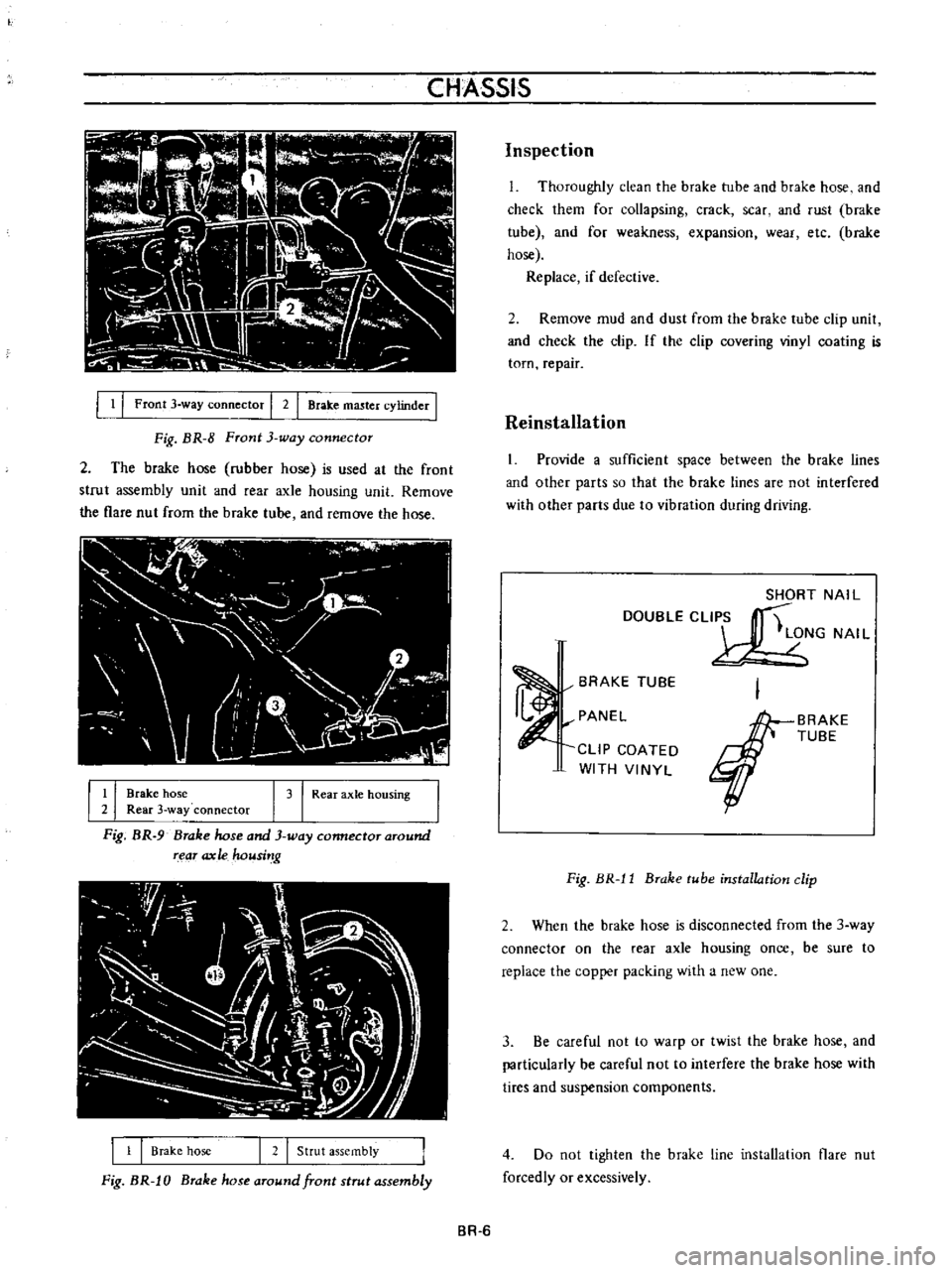
1
I
Front
3
way
connector
I
2
I
Brake
master
cylinder
I
Fig
BR
8
Front
3
way
connector
2
The
brake
hose
rubber
hose
is
used
at
the
front
strut
assembly
unit
and
fear
axle
housing
unit
Remove
the
flare
nut
from
the
brake
tube
and
remove
the
hose
I
r
I
I
l
j
u
l
I
J
II
V
r
1
0
l
I
l
I
I
Brake
hose
I
3
I
Rear
axle
hOUSing
2
Rear
3
way
connector
Fig
BR
9
Brake
hose
and
3
way
connector
around
rear
ax
Ie
housi
g
1
1
Brake
hose
I
2
I
Strut
assembly
Fig
BR
J
0
Brake
hose
around
front
strut
assembly
Inspection
L
Thoroughly
clean
the
brake
tube
and
brake
hose
and
check
them
for
collapsing
crack
scar
and
rust
brake
tube
and
for
weakness
expansion
wear
etc
brake
hose
Replace
if
defective
2
Remove
mud
and
dust
from
the
brake
tube
clip
unit
and
check
the
clip
If
the
clip
covering
vinyl
coating
is
torn
repair
Reinstallation
1
Provide
a
sufficient
space
between
the
brake
lines
and
other
parts
so
that
the
brake
lines
are
not
interfered
with
other
parts
due
to
vibration
during
driving
SHORT
NAIL
DOUBLECLI
S
t
LONG
NAI
L
BRAKE
TUBE
PANEL
CLIP
COATED
WITH
VINYL
BRAKE
TUBE
Fig
BR
l1
Brake
tube
installation
clip
2
When
the
brake
hose
is
disconnected
from
the
3
way
connector
on
the
rear
axle
housing
once
be
sure
to
replace
the
copper
packing
with
a
new
one
3
Be
careful
not
to
warp
or
twist
the
brake
hose
and
particularly
be
careful
not
to
interfere
the
brake
hose
with
tires
and
suspension
components
4
Do
not
tighten
the
brake
line
installation
flare
nut
forcedly
or
excessively
BR
6
Page 150 of 513
CHASSIS
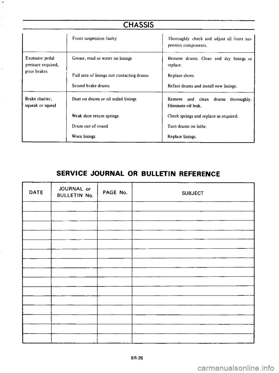
Front
suspension
faulty
Thoroughly
check
and
adjust
all
front
sus
pension
components
Excessive
pedal
pressure
required
poor
brakes
Grease
mud
or
water
on
linings
Remove
drums
Clean
and
dry
linings
or
replace
Full
area
of
linings
not
contacting
drums
Replace
shoes
Scored
brake
drums
Reface
drums
and
install
new
linings
Brake
chatter
squeak
or
squeal
Dust
on
drums
or
oil
soiled
linings
Remove
and
clean
drums
thoroughly
Eliminate
oil
leak
Weak
shoe
return
springs
Check
springs
and
replace
as
required
Drum
out
of
round
Turn
drums
on
lathe
Worn
linings
Replace
linings
SERVICE
JOURNAL
OR
BULLETIN
REFERENCE
DATE
JOURNAL
or
BULLETIN
No
PAGE
No
SUBJECT
BR
26
Page 156 of 513
WHEEL
AND
TIRE
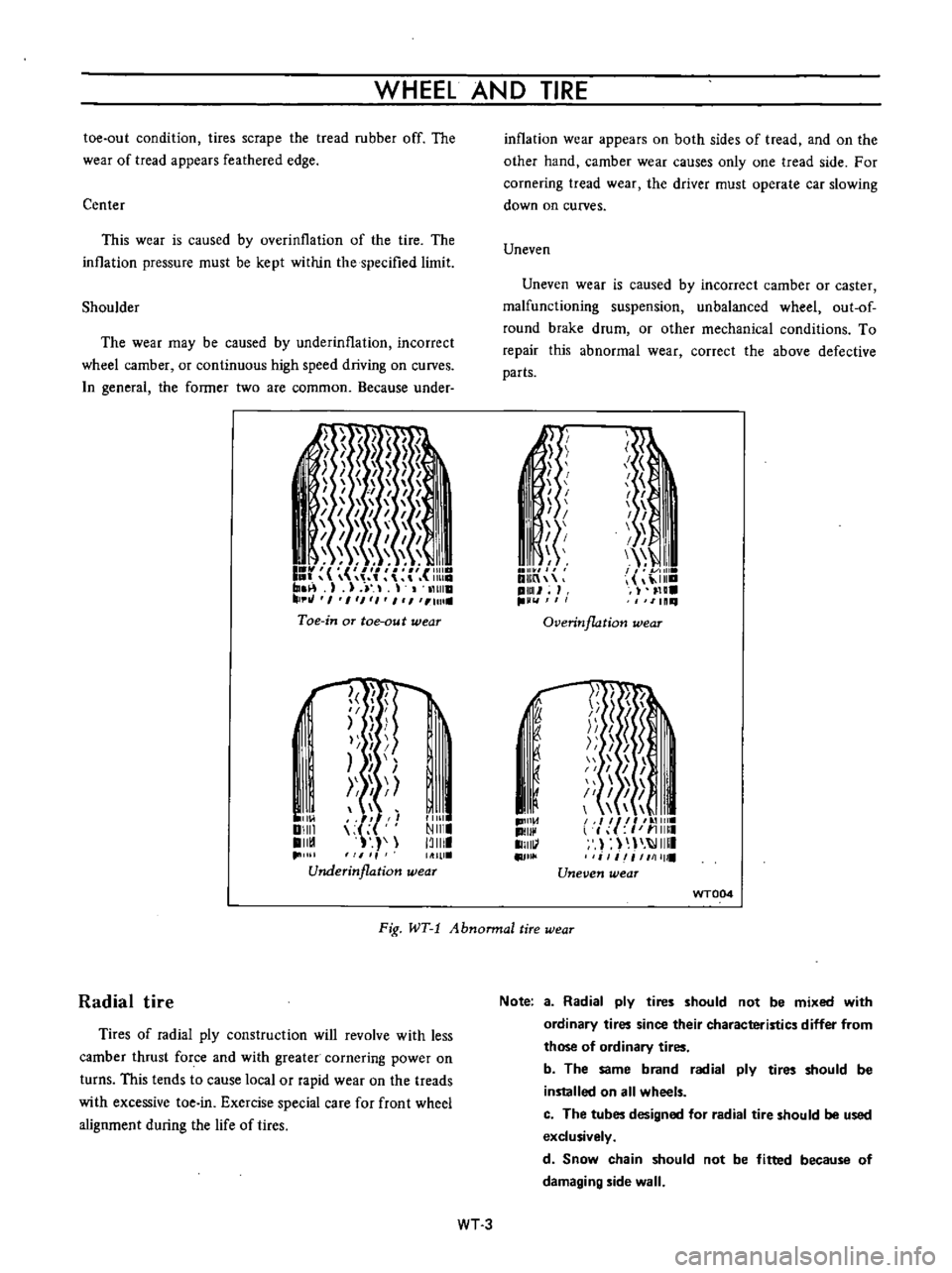
toe
out
condition
tires
scrape
the
tread
rubber
off
The
wear
of
tread
appears
feathered
edge
Center
This
wear
is
caused
by
overinllation
of
the
tire
The
inllation
pressure
must
be
kept
within
the
specified
limit
Shoulder
The
wear
may
be
caused
by
underinflation
incorrect
wheel
camber
or
continuous
high
speed
driving
on
curves
n
general
the
former
two
are
common
Because
under
I
I
I
I
1
1111
I
r
r
m
1
J
11
tHlla
tJ
I
1
1
1
I
1
Ull
Toe
in
aT
toe
au
t
wear
l
f
I
II
I
I
I
I
Ill
Ill
Underinflation
wear
I
11
01
DIIII
II
1
11111
NIII
13111
inflation
wear
appears
on
both
sides
of
tread
and
on
the
other
hand
camber
wear
causes
only
one
tread
side
For
cornering
tread
wear
the
driver
must
operate
car
slowing
down
on
curves
Uneven
Uneven
wear
is
caused
by
incorrect
camber
or
caster
malfunctioning
suspension
unbalanced
wheel
out
of
round
brake
drum
or
other
mechanical
conditions
To
repair
this
abnormal
wear
correct
the
above
defective
parts
Ii
I
I
I
I
1
i
f
I
I
I
I
I
III
I
I
11
DlIIn
ilia
pml
H
IlLl
11111
Overinflation
wear
1D1I1
d
II
1I111
II
j
J
1
51
I
I
I
1
il
I
I
II
l
f
I
11
11111
I
IIIII
i
1
iI
1111111
Uneven
wear
f
I
I
u
WT004
Fig
WT
1
Abnonnal
tire
wear
Radial
tire
Tires
of
radial
ply
construction
will
revolve
with
less
camber
thrust
force
and
with
greater
cornering
power
on
turns
This
tends
to
cause
local
or
rapid
wear
on
the
treads
with
excessive
toe
in
Exercise
special
care
for
front
wheel
alignment
during
the
life
of
tires
Note
a
Radial
ply
tires
should
not
be
mixed
with
ordinary
tires
since
their
characteristics
differ
from
those
of
ordinary
tires
b
The
same
brand
radial
ply
tires
should
be
installed
on
all
wheels
c
The
tubes
designed
for
radial
tire
should
be
used
exclusively
d
Snow
chain
should
not
be
fitted
because
of
damaging
side
wall
WT3
Page 158 of 513
WHEEL
AND
TIRE
Note
In
replacing
tire
take
extra
care
not
to
damage
tire
bead
rim
flange
and
bead
seat
Do
not
use
tire
irons
to
force
beads
away
from
wheel
rim
flange
that
is
always
use
tire
replace
ment
device
whenever
tire
is
removed
WT005
2
Discard
when
any
of
the
following
trouble
occurs
I
Broken
or
damaged
bead
wire
2
Ply
or
tread
separation
3
Worn
febric
damage
on
tubeless
tire
4
Cracked
or
damaged
side
wall
etc
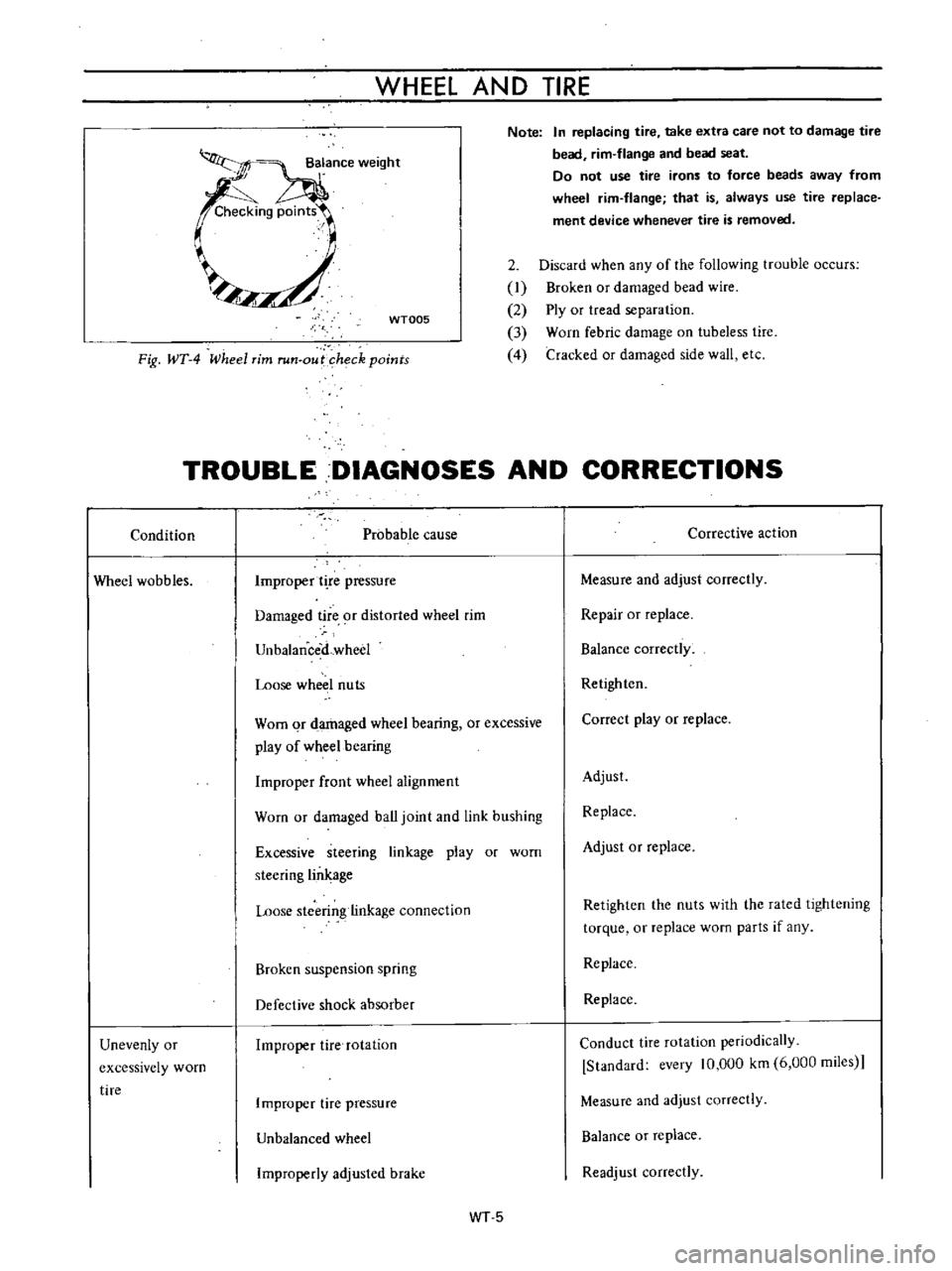
Fig
WT
4
Wheel
rim
run
out
heck
points
TROUBLE
DIAGNOSES
AND
CORRECTIONS
Condition
Probable
cause
Corrective
action
Wheel
wobbles
Improper
t
re
pressure
Measure
and
adjust
correctly
Damaged
tire
9f
distorted
wheel
rim
Repair
or
replace
UnbalanceiLwheel
Balance
correctly
Loose
wheel
nuts
Retighten
Worn
qr
damaged
wheel
bearing
or
excessive
play
of
wheel
bearing
Correct
play
or
replace
Improper
front
wheel
alignment
Adjust
Worn
or
damaged
ball
joint
and
link
bushing
Replace
Excessive
steering
linkage
play
or
worn
steering
lin
age
Adjust
or
replace
Loose
stcerin
linkage
connection
Retighten
the
nuts
with
the
rated
lightening
torque
or
replace
worn
parts
if
any
Broken
suspension
spring
Replace
Defective
shock
absorber
Replace
Unevenly
or
excessively
worn
tire
Improper
tire
rotation
Conduct
tire
rotation
periodically
Standard
every
10
000
km
6
000
miies
Improper
tire
pressure
Measure
and
adjust
correctly
Unbalanced
wheel
Balance
or
replace
Improperly
adjusled
brake
Readjust
correctly
WT5