1973 DATSUN B110 suspension
[x] Cancel search: suspensionPage 95 of 513
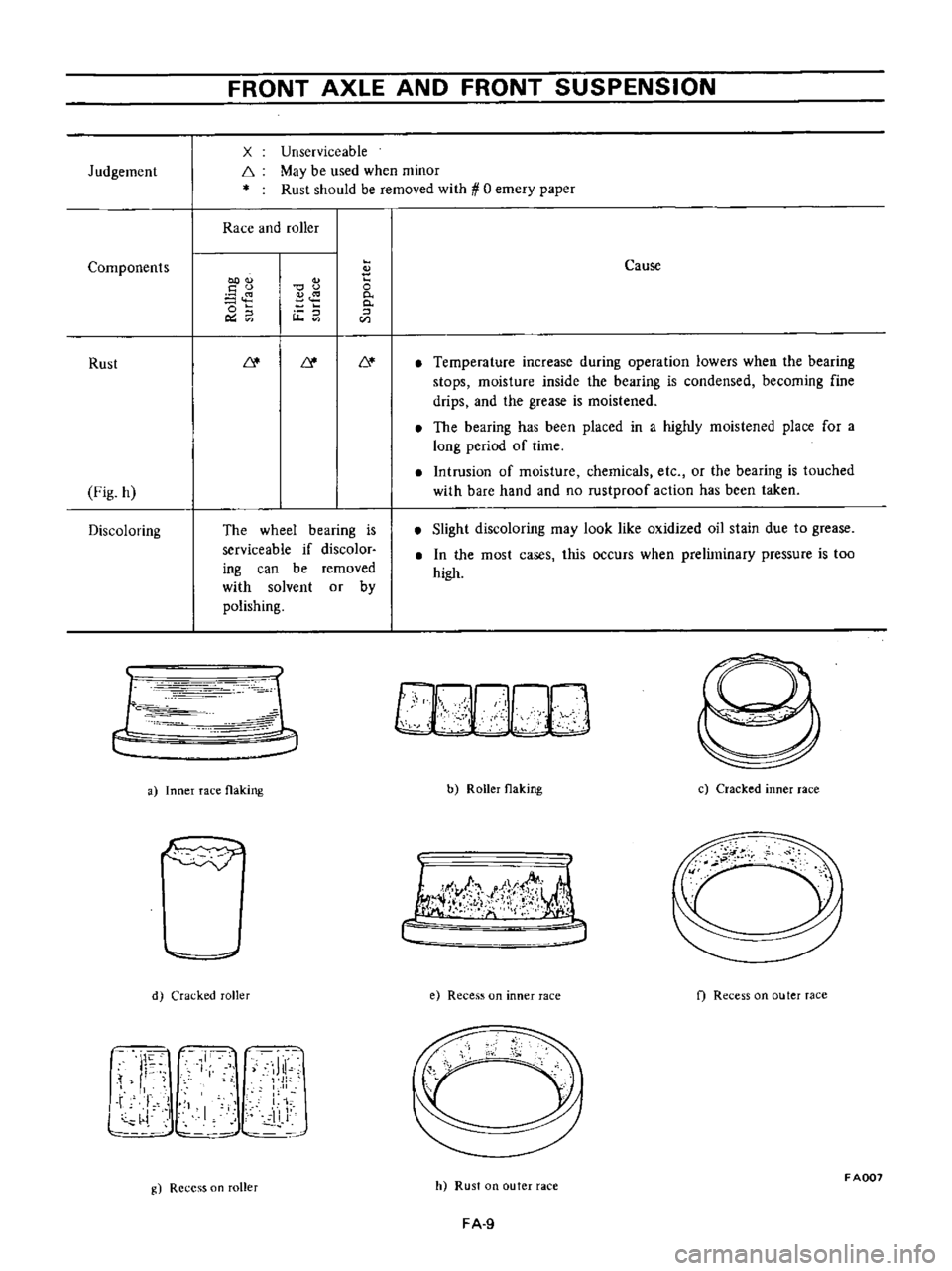
Judgement
Components
Rust
Fig
h
Discoloring
FRONT
AXLE
AND
FRONT
SUSPENSION
x
f
Unserviceable
May
be
used
when
minor
Rust
should
be
removed
with
0
emery
paper
Race
and
roller
00
u
o
o
Ou
u
The
wheel
bearing
is
serviceable
if
discolor
ing
can
be
removed
with
solvent
or
by
polishing
r
c
1
1
Ie
r
r
iJ
a
Inner
race
flaking
d
Cracked
roller
J
I
11
Ji
l
L
i
I
11
J
g
Recess
on
roller
o
0
0
CIl
Cause
Temperature
increase
during
operation
lowers
when
the
bearing
stops
moisture
inside
the
bearing
is
condensed
becoming
fine
drips
and
the
grease
is
moistened
The
bearing
has
been
placed
in
a
highly
moistened
place
for
a
long
period
of
time
Intrusion
of
moisture
chemicals
etc
or
the
bearing
is
touched
with
bare
hand
and
no
rustproof
action
has
been
taken
Slight
discoloring
may
look
like
oxidized
oil
stain
due
to
grease
In
the
most
cases
this
occurs
when
preliminary
pressure
is
too
high
b
Roller
flaking
c
Cracked
inner
race
I
lJ
f
t
j
e
Recess
on
inner
race
f
Recess
on
outer
race
cc
h
Rust
on
outer
race
FADD7
FA
9
Page 97 of 513
FRONT
AXLE
FRONT
SUSPENSION
t
t
Fig
FA
26
Returning
wheel
bearing
lock
nut
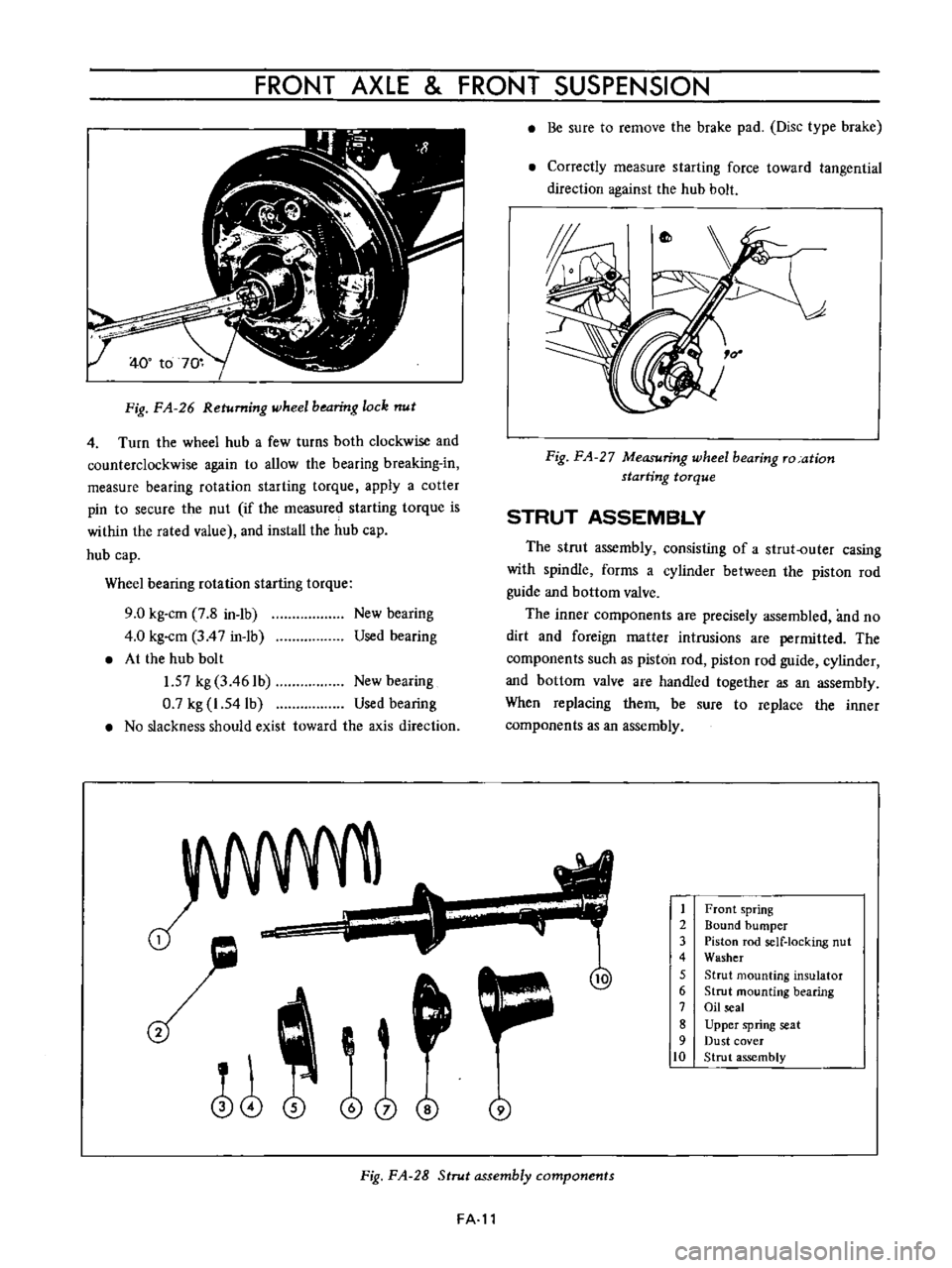
4
Turn
the
wheel
hub
a
few
turns
both
clockwise
and
counterclockwise
again
to
allow
the
bearing
breaking
in
measure
bearing
rotation
starting
torque
apply
a
cotter
pin
to
secure
the
nut
if
the
measured
starting
torque
is
within
the
rated
value
and
install
the
hub
cap
hub
cap
Wheel
bearing
rotation
starting
torque
9
0
kg
cm
7
8
in
1b
4
0
kg
cm
3
4
7
in
1b
At
the
hub
bolt
1
57
kg
3
461b
New
bearing
0
7
kg
1
54lb
Used
bearing
No
slackness
should
exist
toward
the
axis
direction
New
bearing
Used
bearing
J
o
i
@
j
Be
sure
to
remove
the
brake
pad
Disc
type
brake
Correctly
measure
starting
force
toward
tangential
direction
against
the
hub
bolt
Fig
FA
27
Measuring
wheel
bearing
ro
ation
starting
torque
STRUT
ASSEMBLY
The
strut
assembly
consisting
of
a
strut
outer
casing
with
spindle
forms
a
cylinder
between
the
piston
rod
guide
and
bottom
valve
The
inner
components
are
precisely
assembled
and
no
dirt
and
foreign
matter
intrusions
are
permitted
The
components
such
as
piston
rod
piston
rod
guide
cylinder
and
bottom
valve
are
handled
together
as
an
assembly
When
replacing
them
be
sure
to
replace
the
inner
components
as
an
assembly
1
2
3
4
5
6
7
8
9
10
Front
spring
Bound
bumper
Piston
rod
self
locking
nut
Washer
Strut
mounting
insulator
Strut
mounting
bearing
Oil
seal
Upper
spring
seat
Dust
cover
Strut
assembly
Fig
FA
28
Strut
assembly
components
FA
l1
Page 98 of 513
fl
i
i
I
1
I
I
i
2
4
L
thi7
lrr
I
1
1
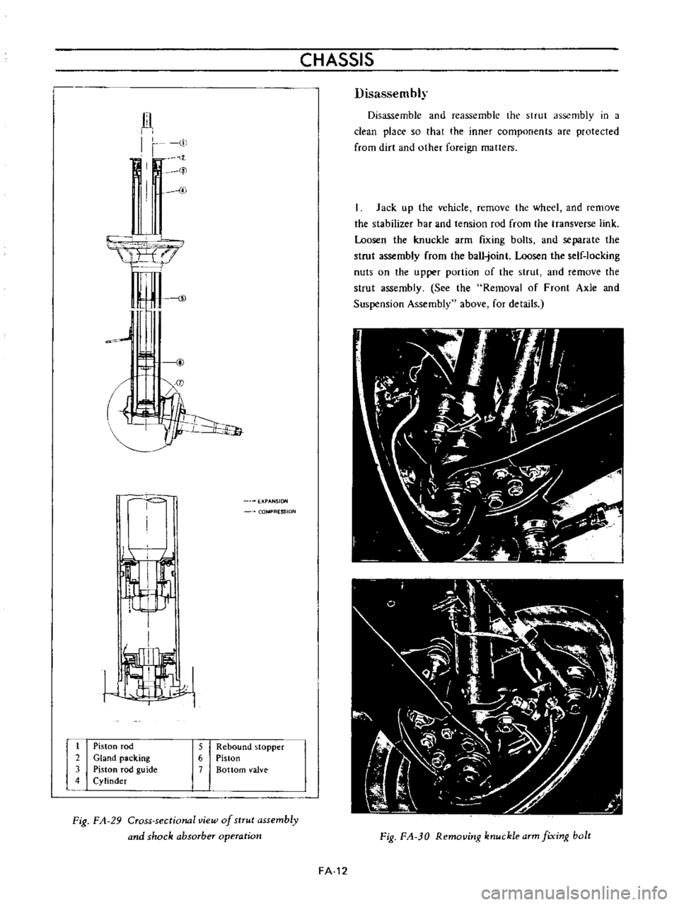
Piston
rod
2
Gland
packing
3
Piston
rod
guide
4
Cylinder
CHASSIS
ESSION
5
Rebound
stopper
6
Piston
7
Bottom
valve
Fig
FA
29
Cross
sectional
view
of
strut
assembly
and
shock
absorber
operation
Disassembly
Disassemble
and
reassemble
the
strut
assembly
in
a
clean
place
so
that
the
inner
components
are
protected
from
dirt
and
other
foreign
matters
Jack
up
the
vehicle
remove
the
wheel
and
remove
the
stabilizer
bar
and
tension
rod
from
the
transverse
link
Loosen
the
knuckle
arm
fIxing
bolts
and
separate
the
strut
assembly
from
the
ball
joint
Loosen
the
self
locking
nuts
on
the
upper
portion
of
the
strut
and
remove
the
strut
assembly
See
the
Removal
of
Front
Axle
and
Suspension
Assembly
above
for
details
Fig
FA
JO
Removitlg
ktluckle
arm
fixitlg
bolt
FA
12
Page 99 of 513
FRONT
AXLE
FRONT
SUSPENSION
Fig
FA
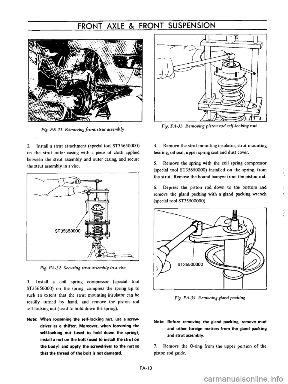
31
Removing
front
strut
assembly
2
InstaU
a
strut
attachment
special
tool
ST35650000
00
the
strut
outer
casing
with
a
piece
of
cloth
applied
between
the
strut
assembly
and
outer
casing
and
secure
the
strut
assembly
in
a
vise
J
1
i
kj
ST35650000
W
lL
bi
Fig
FA
32
Securing
strut
assembly
in
a
vise
3
1nstaU
a
coil
spring
compressor
special
tool
ST35650000
on
the
spring
compress
the
spring
up
to
such
an
extent
that
the
strut
mounting
insulator
can
be
readily
turned
by
hand
and
remove
the
piston
rod
self
locking
nut
used
to
hold
down
the
spring
Note
When
loosening
the
self
locking
nut
use
a
screw
driver
as
a
shitter
Moreover
when
loosening
the
self
locking
nut
used
to
hold
down
the
spring
install
a
nut
on
the
bolt
used
to
install
the
strut
on
the
body
and
apply
the
saewdrivOI
to
the
nut
so
that
the
thread
of
the
bolt
is
not
damaged
r
U
jlD
L1
19
71
it
fr
Fig
FA
33
Removing
piston
rod
self
locking
nut
4
Remove
the
strut
mounting
insulator
strut
mounting
bearing
oil
seal
upper
spring
seat
and
dust
cover
5
Remove
the
spring
with
the
coil
spring
compressor
special
tool
ST35650000
installed
on
the
spring
from
the
strut
Remove
the
bound
bamrer
from
the
piston
rod
6
Depress
the
piston
rod
down
to
the
bottom
and
remove
the
gland
packing
with
a
gland
packing
wrench
special
tool
ST35500000
I
ST35500000
Fig
FA
34
Remvoing
gland
packing
Note
Before
removing
the
gland
packing
remove
mud
and
other
foreign
matters
from
the
gland
packing
and
strut
assembly
7
Remove
the
O
ring
from
the
upper
portion
of
the
piston
rod
guide
FA
13
Page 101 of 513
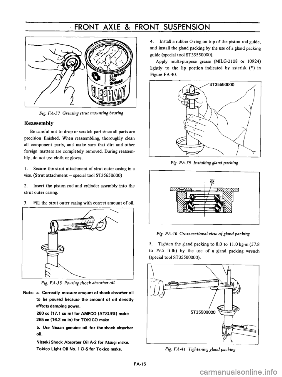
FRONT
AXLE
FRONT
SUSPENSION
I
f
f
ij
Reassembly
Fig
FA
37
Greasing
strut
mounting
bearing
Be
careful
not
to
drop
or
scratch
part
since
all
parts
are
precision
finished
When
reassembling
thoroughly
clean
all
component
parts
and
make
sure
that
dirt
and
other
foreign
matters
are
completely
removed
During
reassem
bly
do
not
use
cloth
or
gloves
I
Secure
the
strut
attachment
of
strut
Quter
casing
in
a
vise
Strut
attachment
special
tool
ST35650000
2
Insert
the
piston
rod
and
cylinder
assembly
into
the
strut
outer
casing
3
Fill
the
strut
outer
casing
with
correct
amount
of
oil
1
Fig
FA
38
Pouring
shock
absorber
oil
Note
a
Correctly
measure
amount
of
shock
absorber
oil
to
be
poured
because
the
amount
of
oil
directly
affects
damping
power
280
cc
17
1
cu
in
for
AMPCO
ATSUGI
make
265
cc
16
2
cu
in
for
TOKICO
make
b
Use
Nissan
genuine
oil
for
the
shock
absorber
oil
Nisseki
Shock
Absorber
Oil
A
2
for
Atsugi
make
Tokico
light
Oil
No
1
D
S
for
Tokico
make
FA
15
4
Install
a
rubber
O
ring
on
top
of
the
piston
rod
guide
and
install
the
gland
packing
by
the
use
of
a
gland
packing
guide
special
tool
ST35550000
Apply
multi
purpose
grease
MILG
2108
or
10924
lightly
to
the
lip
portion
indicated
by
asterisk
0
in
Figure
F
A40
ST35550000
1
Fig
FA
39
Installing
gland
packing
a
1
c
I
Fig
FA
40
Cross
sectional
view
of
gland
packing
5
Tighten
the
gland
packing
to
8
0
to
11
0
kg
m
57
8
to
79
5
ft
1b
by
the
use
of
a
gland
packing
wrench
special
tool
ST35500000
ST35500000
Fig
FA
41
Tighrening
gland
packing
Page 103 of 513
FRONT
AXLE
FRONT
SUSPENSION
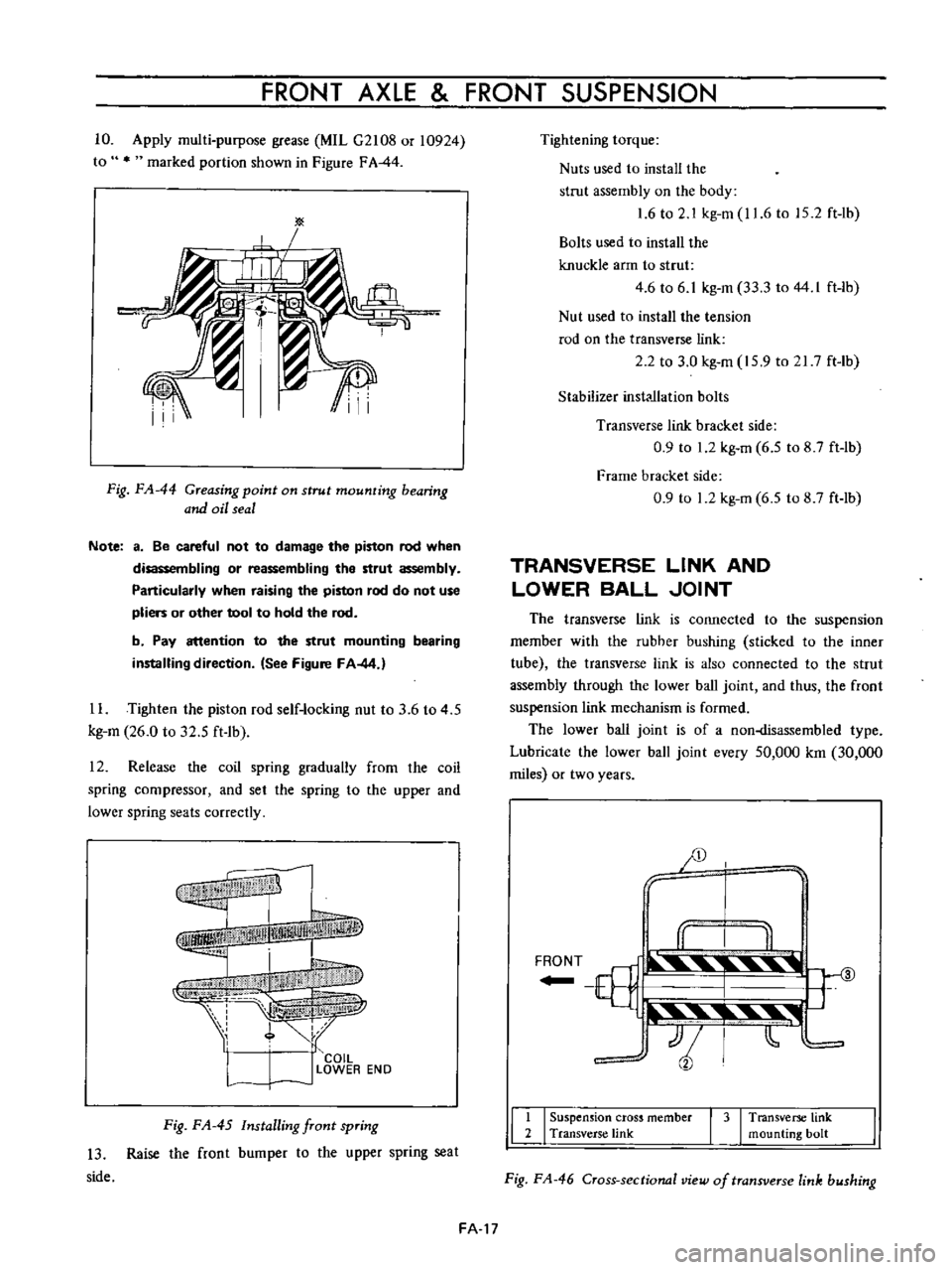
10
Apply
multi
purpose
grease
MIL
G2108
or
10924
to
marked
portion
shown
in
Figure
FA
44
Fig
FA
44
Greasing
point
on
strut
mounting
bearing
and
oil
seal
Note
a
Be
careful
not
to
damage
the
piston
rod
when
disassembling
or
reassembling
the
strut
assembly
Particularly
when
raising
the
piston
rod
do
not
use
pliers
or
other
tool
to
hold
the
rod
b
Pay
attention
to
the
strut
mounting
bearing
installing
direction
See
Figure
FA
44
1
L
Tighten
the
piston
rod
self
locking
nut
to
3
6
to
4
5
kg
m
26
0
to
32
5
ft
1b
12
Release
the
coil
spring
gradually
from
lhe
coil
spring
compressor
and
set
the
spring
to
the
upper
and
lower
spring
seats
correctly
f
I
I
COIL
l
J
LOWER
EN
D
Fig
FA
45
Installing
front
spring
13
Raise
the
front
bumper
to
the
upper
spring
seat
side
Tightening
torque
Nuts
used
to
install
the
strut
assembly
on
the
body
1
6
to
2
1
kg
m
11
6
to
15
2
ft
lb
Bolts
used
to
install
the
knuckle
arm
to
strut
4
6
to
6
1
kg
m
33
3
to
44
I
ft
lb
Nut
used
to
install
the
tension
rod
on
the
transverse
link
2
2
to
3
0
kg
m
15
9
to
21
7
ft
Ib
Stabilizer
inst
llation
bolts
Transverse
link
bracket
side
0
9
to
1
2
kg
m
6
5
to
8
7
ft
lb
Frame
bracket
side
0
9
to
1
2
kg
m
6
5
to
8
7
ft
lb
TRANSVERSE
LINK
AND
LOWER
BALL
JOINT
The
transverse
link
is
connected
to
the
suspension
member
with
the
rubher
bushing
sticked
to
the
inner
tube
the
transverse
link
is
also
connected
to
the
strut
assembly
through
the
lower
ball
joint
and
thus
the
front
suspension
link
mechanism
is
formed
The
lower
ball
joint
is
of
a
non
lisassembled
type
Lubricate
the
lower
ball
joint
every
50
000
km
30
000
miles
or
two
years
JD
y
I
II
I
II
F
T
ill
3
YJ
t
tjli
t
11
I
Suspension
cross
member
I
3
I
Transverse
link
2
Transverse
link
mounting
bolt
Fig
FA
46
Cross
sectional
view
of
transverse
link
bushing
FA
17
Page 104 of 513
CHASSIS
r
I
El
0
3
to
1
0
mm
0
0118
to
0
0394
in
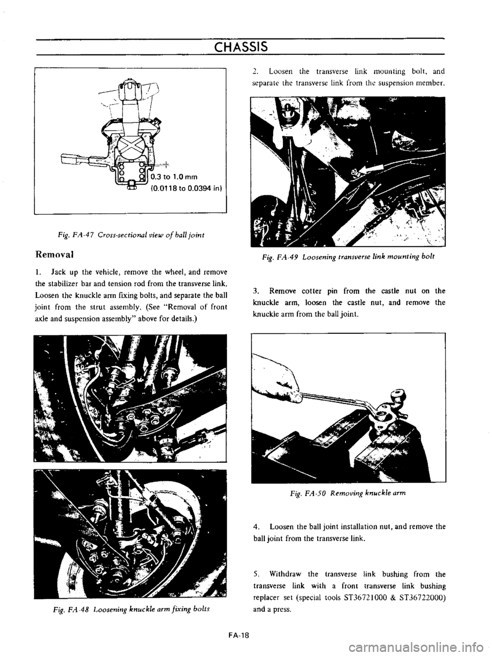
Fig
FA
47
Cross
sectional
vie
of
ball
joint
Removal
1
Jack
up
the
vehicle
remove
the
wheel
and
remove
the
stabilizer
bar
and
tension
rod
from
the
transverse
link
Loosen
the
knuckle
arm
fiXing
bolts
and
separate
the
ball
joint
from
the
strut
assembly
See
Removal
of
front
axle
and
suspension
assembly
above
for
details
Fig
FA
48
Loosening
knuckle
arm
fixing
bolts
2
Loosen
the
transverse
link
mounting
bolt
and
separate
the
transverse
link
from
the
suspension
member
Fig
FA
49
Loosening
transverse
link
mounting
bolt
3
Remove
cotter
pin
from
the
castle
nut
on
the
knuckle
arm
loosen
the
castle
nut
and
remove
the
knuckle
arm
from
the
ball
joint
J
iIP
A
i
Fig
FA
50
Removing
knuckle
arm
4
Loosen
the
ball
joint
installation
nut
and
remove
the
haJJ
joint
from
the
transverse
Jink
5
Withdraw
the
transverse
link
bushing
from
the
transverse
link
with
a
front
transverse
link
bushing
replacer
set
special
tools
ST36721000
ST36722000
and
a
press
FA
18
Page 105 of 513
FRONT
AXLE
FRONT
SUSPENSION
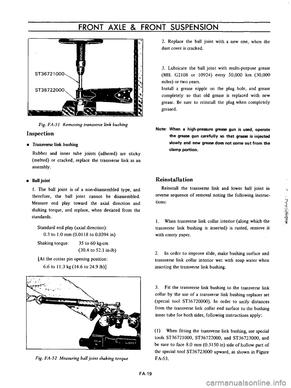
I
ST36721
000
ST36722000
Fig
FA
51
Removing
transverse
link
bushing
Inspection
Transverse
link
bushing
Rubber
and
inner
tube
joints
adhered
are
sticky
melted
or
cracked
replace
the
transverse
link
as
an
assembly
Ball
joint
I
The
ball
joint
is
of
a
non
disassembled
type
and
therefore
the
ball
joint
cannot
be
disassembled
Measure
end
play
toward
the
axial
direction
and
shaking
torque
and
replace
when
deviated
from
the
standards
Standard
end
play
axial
direction
0
3
to
1
0
mm
0
0118
to
0
0394
in
Shaking
torque
35
to
60
kg
cm
30
4
to
52
1
in
ib
At
the
cotter
pin
opening
position
6
6
to
11
3
kg
14
6
to
24
9Ib
I
Fig
FA
52
Measuring
ball
joint
shaking
torque
2
Replace
the
ball
joint
with
a
new
one
when
the
dust
cover
is
cracked
3
Lubricate
the
ball
joint
with
multi
purpose
grease
MIL
G2108
or
10924
every
50
000
km
30
000
miles
or
two
years
Install
a
grease
nipple
on
the
plug
hole
and
grease
completely
so
that
old
grease
is
replaced
with
new
grease
Be
sure
to
reinstall
the
plug
when
completely
greased
Note
When
a
high
pressure
grease
gun
is
used
operate
the
grease
gun
carefully
so
that
grease
is
injected
slowly
and
new
grease
does
not
come
out
from
the
clamp
portion
Reinstallation
Reinstall
the
transve
l
e
link
and
lower
ball
joint
in
reverse
sequence
of
removal
noting
the
following
ins
true
tions
I
When
transverse
link
collar
interior
along
which
the
transverse
link
bushing
is
inserted
is
rusted
remove
it
with
emery
paper
2
In
order
to
improve
slide
make
bushing
surface
and
transverse
link
collar
interior
wet
with
soap
water
when
inserting
the
transverse
link
bushing
3
Fit
the
transverse
link
bushing
to
the
transverse
link
collar
by
the
use
of
a
transverse
link
bushing
replacer
set
special
1001
ST36720000
In
order
to
unify
distances
from
the
transverse
link
collar
end
surface
to
the
bushing
inner
tube
for
both
sides
following
instructions
apply
1
When
fitting
the
transve
l
e
link
bushing
use
special
tools
ST36721000
ST36722000
and
ST36723000
and
be
sure
to
face
8
0
mm
0
3150
in
side
of
hollow
part
of
the
special
tool
ST36723000
upward
as
shown
in
Figure
FA
53
FA
19