1973 DATSUN B110 oil filter
[x] Cancel search: oil filterPage 274 of 513
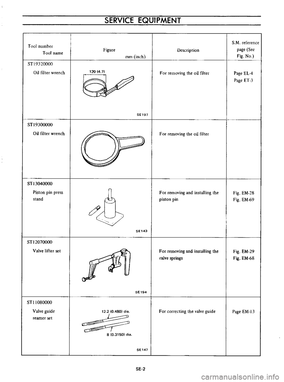
Tool
number
T
ooJ
name
ST
I
9320000
Oil
filter
wrench
STl9300000
Oil
ftIter
wrench
STl3040000
Piston
pin
press
stand
STl2070000
Valve
lifter
set
STl1080000
Valve
guide
reamer
set
SERVICE
EQUIPMENT
Figure
mm
inch
120
14
7
SE197
11
0
SE143
SE194
12
210
4801
d
8
L
8
10
31501
d
a
SE147
SE
2
Description
For
removing
the
oil
filter
For
removing
the
oil
filter
For
removing
and
installing
the
piston
pin
For
removing
and
installing
the
a1ve
springs
For
correcting
the
valve
guide
S
M
reference
page
See
Fig
No
Page
EL
4
Page
ET
3
Fig
EM
28
Fig
EM
69
Fig
EM
29
Fig
EM
68
Page
EM
13
Page 306 of 513

EMISSION
CONTROL
AND
TUNE
UP
EMISSION
CONTROL
SYSTEM
AN
D
ENGINE
TUNE
UP
CONTENTS
BASIC
MECHANICAL
SYSTEM
ET
Checking
and
adjusting
dash
pot
Adjusting
intake
and
exhaust
valve
automatic
transmission
model
only
ET
9
clearances
ET
1
Checking
carburetor
return
spring
ET
9
Checking
and
adjustin9
drive
belt
ET
2
Checking
choke
mechanism
choke
valve
Retightening
cylinder
head
bolts
manifold
and
linkagel
ET
9
nuts
and
carburetor
securing
nuts
ET
2
Checking
anti
dieseling
solenoid
ET
9
Checking
engine
oil
ET
2
Replacing
fuel
filter
ET
10
Replacing
oil
filter
ET
3
Checking
fuel
lines
hoses
pipings
Changing
engine
coolant
L
L
C
ET
3
connections
etc
ET10
Checking
cooling
system
hoses
and
THROTTLE
OPENER
CONTROL
SYSTEM
ET
10
connections
ET
4
Checking
and
adjusting
throttle
opener
ET
13
Checking
vacuum
fittings
hoses
and
TRANSMISSION
CONTROLLED
VACUUM
connections
ET
4
ADVANCE
SYSTEM
ET
17
Checking
engine
compression
ET
4
Checking
electrical
advance
control
system
ET
19
Checking
exhaust
manifold
heat
control
AUTOMATIC
TEMPERATURE
CONTROL
AIR
valve
ET
5
CLEANER
A
T
C
AIR
CLEANER
ET
20
IGNITION
AND
FUEL
SYSTEM
ET
5
Replacing
carburetor
air
cleaner
filter
ET
20
Checking
battery
ET
5
Checking
hot
air
control
valve
ET
20
Checking
and
adjusting
ignition
timing
ET
5
CRANKCASE
EMISSION
CONTROL
Checking
or
replacing
distributor
breaker
SYSTEM
ET
22
point
condenser
and
spark
plugs
ET
6
Checking
or
replacing
PCV
valve
ET
23
Checking
distributor
ignition
wiring
and
Checking
ventilation
hoses
ET
23
ignition
coil
ET
7
EVAPORATIVE
EMISSION
CONTROL
Checking
distributor
cap
and
rotor
ET
7
SYSTEM
ET
23
Adjusting
carburetor
id
Ie
rpm
and
Checking
engine
compartment
hose
mixture
ratio
ET
8
connections
and
fuel
vapor
control
valves
ET
23
Checking
fuel
tank
vacuum
relief
valve
operation
ET
24
BASIC
MECHANICAL
SYSTEM
1
Start
engine
and
run
it
until
it
is
heated
to
operating
temperature
or
at
least
more
than
800C
I760F
of
engine
oil
temperature
then
stop
engine
Adjusting
intake
and
exhaust
valve
clearances
Valve
clearance
adjustment
should
be
made
while
engine
is
stationary
To
adjust
proceed
as
follows
2
Rotate
crankshaft
to
bring
No
1
cylinder
in
top
dead
center
on
its
compression
stroke
3
Remove
valve
rocker
cover
to
gain
access
to
valve
ET
1
Page 307 of 513
ENGINE
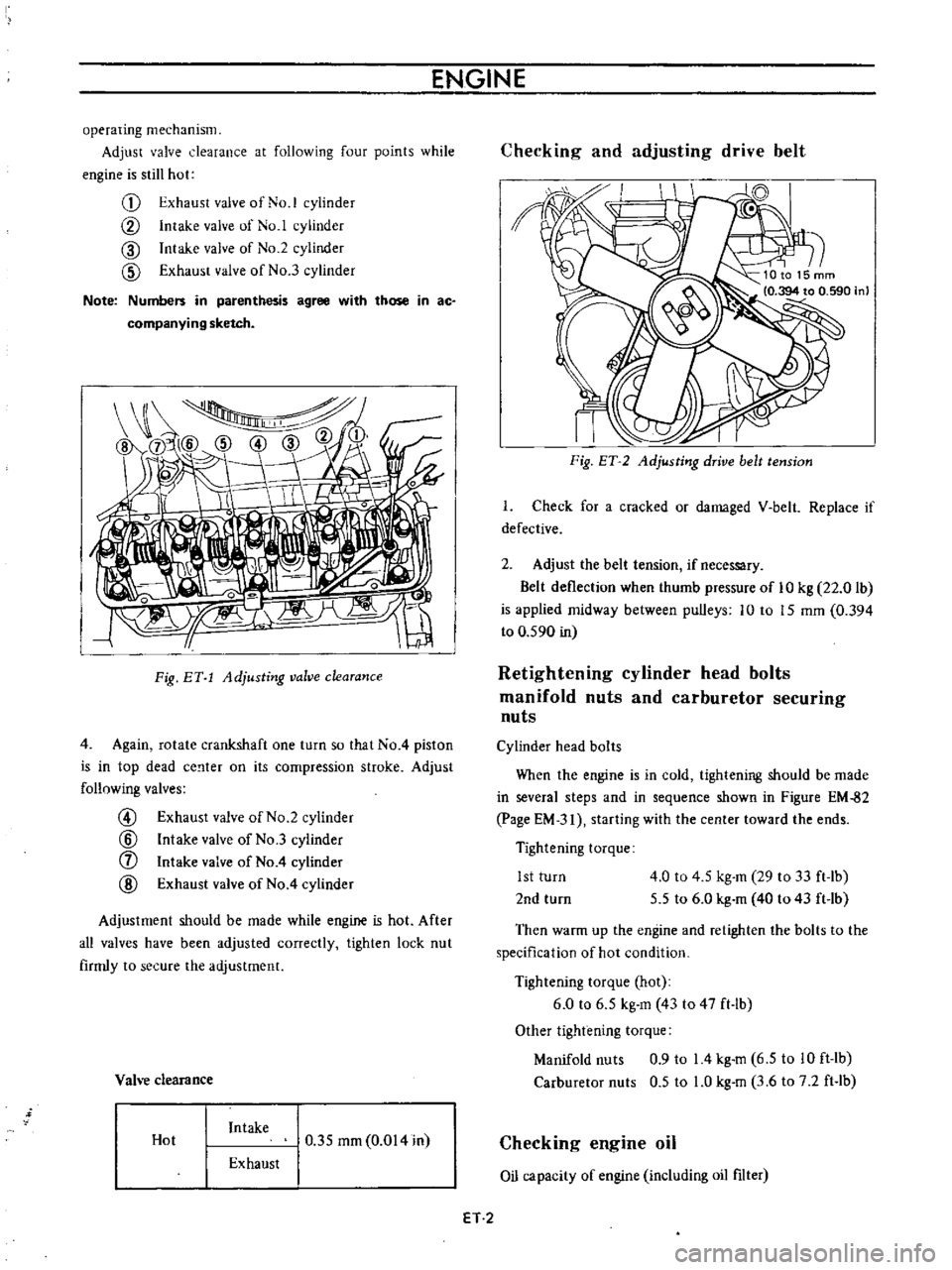
operating
mechanism
Adjust
valve
clearance
at
following
four
points
while
engine
is
still
hot
G
Exhaust
valve
of
No
1
cylinder
CV
Intake
valve
of
No
1
cylinder
CID
Intake
valve
of
No
2
cylinder
CID
Exhaust
valve
of
No
3
cylinder
Note
Numbers
in
parenthesis
agree
with
those
in
ac
companying
sketch
I
Fig
BY
1
Adjusting
valve
clearance
4
Again
rotate
crankshaft
one
turn
so
that
No
4
piston
is
in
top
dead
ce
lter
on
its
compression
stroke
Adjust
follnwing
valves
@
Exhaust
valve
of
No
2
cylinder
@
Intake
valve
of
No
3
cylinder
f
Intake
valve
of
No
4
cylinder
@
Exhaust
valve
of
No
4
cylinder
Adjustment
should
be
made
while
engine
is
hot
After
all
valves
have
been
adjusted
correctly
tighten
lock
nut
firmly
to
secure
the
adjustment
Vah
e
clearance
Hot
Intake
0
35
mm
0
014
in
Exhaust
Checking
and
adjusting
drive
belt
II
I
Fig
ET
2
Adjusting
drive
belt
tension
I
Check
for
a
cracked
or
damaged
V
belt
Replace
if
defective
2
Adjust
the
belt
tension
if
necessary
Belt
deflection
when
thumb
pressure
of
10
kg
22
0
lb
is
applied
midway
between
pulleys
10
to
15
mm
0
394
to
0
590
in
Retightening
cylinder
head
bolts
manifold
nuts
and
carburetor
securing
nuts
Cylinder
head
bolts
When
the
engine
is
in
cold
tightening
should
be
made
in
several
steps
and
in
sequence
shown
in
Figure
EM
82
page
EM
31
starting
with
the
center
toward
the
ends
Tightening
torque
1st
turn
2nd
turn
4
0
to
4
5
kg
m
29
to
33
ft
lb
5
5
to
6
0
kg
m
40
to
43
ft
lb
Then
warm
up
the
engine
and
retighten
the
bolts
to
the
specification
of
hot
condition
Tightening
torque
hot
6
0
to
6
5
kg
m
43
to
47
ft
lb
Other
tightening
torque
Manifold
nuts
0
9
to
14
kg
m
6
5
to
10
ft
lb
Carburetor
nuts
0
5
to
LO
kg
m
3
6
to
7
2
ft
lb
Checking
engine
oil
Oil
capacity
of
engine
including
oil
filter
ET
2
Page 308 of 513
EMISSION
CONTROL
AND
TUNE
UP
Capacity
Maximum
3
3
L
X
US
gal
y
Imp
gal
2
3
L
US
gal
f
Imp
gal
Minimum
Make
sure
that
engine
oil
is
not
deteriorated
with
cooling
water
or
gasoline
Drain
and
refill
the
oil
if
necessary
Notes
a
A
milky
oil
indicates
the
presence
of
cooling
water
Find
the
cause
for
necessary
corrective
action
b
Oil
with
extremely
low
viscosity
indicates
dilution
with
gasoline
2
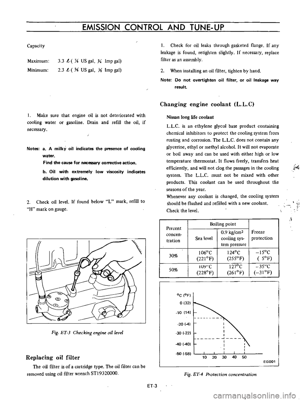
Check
oil
level
If
found
below
L
mark
refill
to
H
mark
on
gauge
Fig
ET
3
Checking
engine
oil
level
Replacing
oil
filter
The
oil
ftIter
is
of
a
cartridge
type
The
oil
filter
can
be
removed
using
oil
ftIter
wrench
STl9320000
Check
for
oil
leaks
through
gasketed
flange
If
any
leakage
is
found
retighten
slightly
If
necessary
replace
filter
as
an
assembly
2
When
installing
an
oil
filter
tighten
by
hand
Note
Do
not
overtighten
oil
filter
or
oil
leakage
way
result
Changing
engine
coolant
L
L
C
Nissan
long
life
coolant
LLC
is
an
ethylene
glycol
base
product
containing
chemical
inhibitors
to
protect
the
cooling
system
from
rusting
and
corrosion
The
L
L
C
does
not
contain
any
glycerine
ethyl
or
methyl
alcohol
It
will
not
evaporate
or
boil
away
and
can
be
used
with
either
high
or
low
temperature
thermostat
It
flows
freely
transfers
heat
efficiently
and
will
not
clog
the
passages
in
the
cooling
system
The
LL
C
must
not
be
mixed
with
other
products
This
coolant
can
be
used
throughout
tlie
seasons
of
the
year
Whenever
any
coolant
is
changed
the
cooling
system
should
be
flushed
and
refilled
with
a
new
coolant
Check
the
level
J
Percent
Boiling
point
0
9
kgfcm2
Freeze
concen
tration
Sea
level
cooling
sys
protection
tern
pressure
30
1060
C
I
240C
15OC
221OF
255OF
5OF
50
IUY
C
1270C
35
C
2280
F
2610F
3IOF
DC
OF
0
321
10
14
20141
50
58
I
I
I
I
1
I
I
1
30
1
22
40
401
40
10
30
50
20
EGOOl
Fig
ET
4
Protection
concentration
ET
3
Page 327 of 513
ENGINE
6
Start
the
engine
and
continue
idling
as
described
under
paragraphs
I
2
and
3
above
When
several
minutes
have
passed
and
the
valve
is
partially
opened
read
the
thermister
indication
It
is
correct
if
the
reading
falls
between
380C
1000
F
and
550C
1300
F
If
the
reading
is
abnormal
replace
the
sensor
7
On
the
engine
equipped
with
an
idle
compensator
as
service
option
do
as
follows
before
replacing
the
sensor
Clog
hose
on
idle
compensator
side
by
twisting
or
clamping
it
and
check
the
temperature
as
given
in
paragraphs
5
and
6
above
If
the
thermometer
shO
vs
correct
temperature
replace
the
idle
compensa
tOf
if
the
reading
is
abnormal
replace
the
sensor
CRANKCASE
EMISSION
CONTROL
SYSTEM
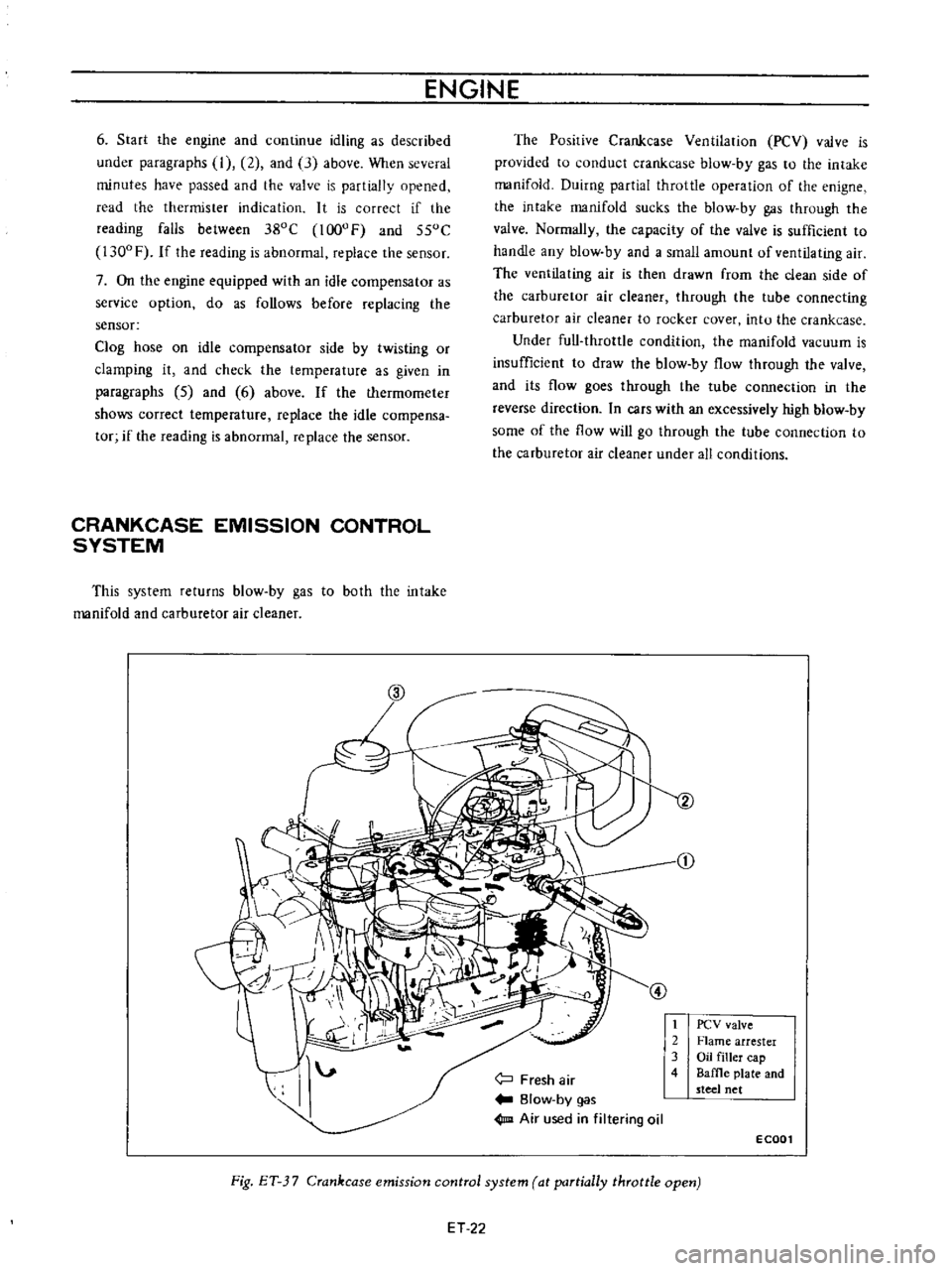
This
system
returns
blow
by
gas
to
both
the
intake
manifold
and
carburetor
air
cleaner
The
Posirive
Crankcase
Ventilation
PCV
valve
is
provided
to
conduct
crankcase
blow
by
gas
to
the
intake
manifold
Duirng
partial
throttle
operation
of
the
enigne
the
intake
manifold
sucks
the
blow
by
gas
through
the
valve
Normally
the
capacity
of
the
valve
is
sufficient
to
handle
any
blow
by
and
a
small
amount
of
ventilating
air
The
ventilating
air
is
then
drawn
from
the
clean
side
of
the
carburetor
air
cleaner
through
the
tube
connecting
carburetor
air
cleaner
to
rocker
cover
intu
the
crankcase
Under
full
throttle
condition
the
manifold
vacuum
is
insufficient
to
draw
the
blow
by
flow
through
the
valve
and
its
flow
goes
through
the
tube
connection
in
the
reverse
direction
In
cars
with
an
excessively
high
blow
by
some
of
the
flow
will
go
through
the
tube
connection
to
the
carburetor
air
cleaner
under
all
conditions
j
Fresh
air
Blow
by
gas
1m
Air
used
in
filtering
oil
t
2
3
4
PCV
valve
Flame
arrester
Oil
filler
cap
Baffle
plate
and
steel
net
ECOOl
Fig
ET
3
7
Crankcase
emission
control
system
at
partially
throttle
open
ET
22
Page 328 of 513

EMISSION
CONTROL
AND
TUNE
UP
CD
@
Fresh
air
Blow
by
gas
Air
used
in
filtering
oil
1
PCV
valve
2
Flame
arrester
3
Oil
filler
cap
4
Baffle
plate
and
steel
net
E
C002
Fig
ET
J8
Crankcase
emission
control
system
at
full
throttle
open
Checking
and
replacing
PCV
valve
Test
PCV
valve
in
accordance
with
the
following
me
thod
With
engine
running
at
idle
remove
the
ventilator
hose
from
PCV
valve
If
the
valve
is
working
a
hissing
noise
will
be
heard
as
air
passes
through
the
valve
and
a
strong
vacuum
should
be
felt
immediately
when
a
finger
is
placed
over
the
valve
inlet
If
the
valve
is
plugged
replace
with
a
new
one
Check
for
deposit
plugging
in
the
hose
Clean
if
necessary
Intake
manifold
l
illlr
nnnl
UUUU
l
I
G
EC014
FigET
39
Cross
sectional
view
of
PCV
valve
Checking
ventilation
hoses
I
Check
hoses
and
hose
connections
for
leaks
2
Disconnect
all
hoses
and
blow
them
out
with
compressed
air
If
any
hose
can
not
be
free
of
obstructions
replace
with
a
new
one
Insure
that
the
flame
arrester
is
surely
inserted
in
the
hose
between
the
air
cleaner
and
rocker
cover
EVAPORATIVE
EMISSION
CONTROL
SYSTEM
Checking
engine
compartment
hose
connections
and
fuel
vapor
control
valves
Checking
fuel
tank
vapor
liquid
separator
and
vapor
vent
line
I
Check
all
hoses
and
fuel
tank
ftIler
cap
2
Disconnect
the
vapor
vent
line
connecting
flow
guide
valve
to
vapor
liquid
separator
ET
23
Page 337 of 513
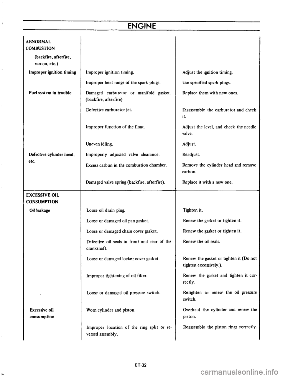
ABNORMAL
COMBUSTION
backfire
afterflfe
run
on
etc
Improper
ignition
timing
Fuel
system
in
trouble
Defective
cylinder
head
etc
EXCESSIVE
OIL
CONSUMPTION
Oil
leakage
Excessive
oil
consumption
ENGINE
Improper
ignition
timing
Improper
heat
range
of
the
spark
plugs
Damaged
carburetor
or
manifold
gasket
backfire
afterflre
Defective
carburetor
jet
Improper
function
of
the
float
Uneven
idling
Improperly
adjusted
valve
clearance
Excess
carbon
in
the
combustion
chamber
Damaged
valve
spring
backfire
afterure
Loose
oil
drain
plug
Loose
or
damaged
oil
pan
gasket
Loose
or
damaged
chain
cover
gasket
Defective
oil
seals
in
front
and
rear
of
the
crankshaft
Loose
or
damaged
locker
cover
gasket
Improper
tightening
of
oil
filter
Loose
or
damaged
oil
pressure
switch
Worn
cylinder
and
piston
Improper
location
of
the
ring
split
or
reo
versed
assembly
ET
32
Adjust
the
ignition
timing
Use
specified
spark
plugs
Replace
them
with
new
ones
Disassemble
the
carburetor
and
check
it
Adjust
the
level
and
check
the
needle
valve
Adjust
Readjust
Remove
the
cylinder
head
and
remove
carbon
Replace
it
with
a
new
one
Tighten
it
Renew
the
gasket
or
tighten
it
Renew
the
gasket
or
tighten
it
Renew
the
oil
seals
Renew
the
gasket
or
tighten
it
Do
not
tighten
excessively
Renew
the
gasket
and
tighten
it
cor
rectly
Retighten
or
renew
the
oil
pressure
switch
Overhaul
the
cylinder
and
renew
the
piston
Reassemble
the
piston
rings
correctly
Page 372 of 513
ENGINE
27
Install
the
oil
pump
with
oil
filter
28
Install
the
alternator
fan
and
fan
belt
29
Install
the
fuel
pump
30
Install
the
distributor
assembly
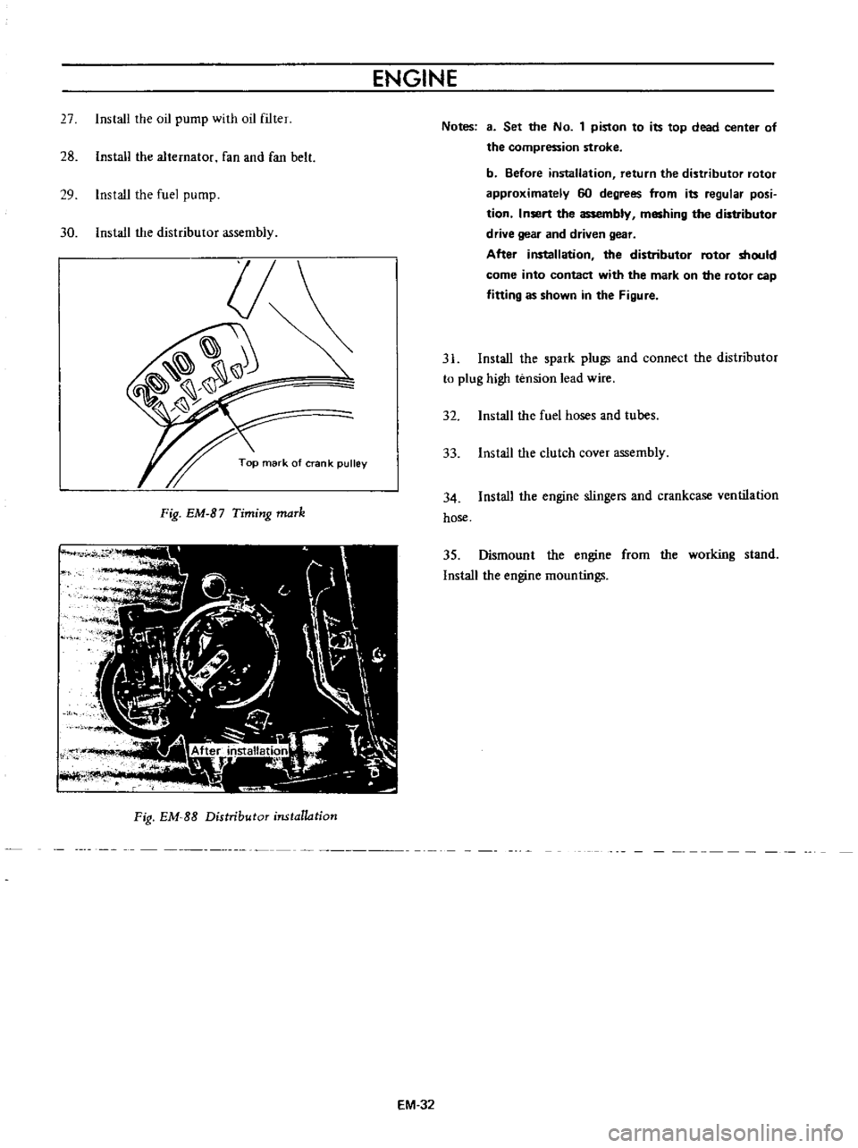
Fig
EM
B7
Timing
maTk
Fig
EM
SS
Distributor
installation
EM
32
Notes
3
Set
the
No
1
piston
to
its
top
dead
center
of
the
compression
stroke
b
Before
installation
return
the
distributor
rotor
approximately
60
degrees
from
its
regular
posi
tion
Insert
the
assembly
meshing
the
distributor
drive
gear
and
driven
gear
After
installation
the
distributor
rotor
should
come
into
contact
with
the
mark
on
the
rotor
cap
fitting
as
shown
in
the
Figure
31
Install
the
spark
plugs
and
connect
the
distributor
to
plug
high
tension
lead
wire
32
Install
the
fuel
hoses
and
tubes
33
Install
the
clutch
cover
assembly
34
Install
the
engine
stingers
and
crankcase
ventilation
hose
35
Dismount
the
engine
from
the
working
stand
Install
the
engine
mountings