Page 194 of 513
J
J
CD
11
BODY
I
K
L
L
N
N
@
r
T
I
c
cb
I
cp
M
M
J
Ii
0
0
SEALING
ON
CIRCUMFERENCE
OF
REAR
FLOOR
@
Ii
DETAILS
OF
Q
PORTION
DETAILS
OF
R
PORTION
1
Rear
floor
2
Rear
fender
3
Luggage
compartment
floor
rear
side
4
Front
pillar
5
Front
fender
6
Ou
tee
door
7
Fue
filler
cover
8
Shock
absorber
mount
bracket
9
Seat
back
support
10
Inner
lock
pillar
11
Lock
pillar
12
Roof
13
Rear
waist
14
Luggage
compartment
lid
15
Rear
panel
16
Outer
wheel
house
Fig
BF
6
Cross
sectional
view
II
BF
4
Page 195 of 513
COUPE
BODY
T
@
T
v
v
vv
l
2
DOOR
1
5
Vv
t
t
tJ
DETAILS
OF
8
PORTION
1
r
I
A
A
J
C
C
j
@
cr
U
D
D
@
DETAILS
OF
E
PORTION
1
Roof
2
Inner
side
body
3
Rear
fender
4
Outer
door
5
Front
pillar
6
Front
fender
7
loner
wheel
house
8
Rear
floor
9
I
Rner
lock
pilla
c
to
Lock
pillar
Fig
BF
7
Cross
sectional
view
III
SF
5
Page 209 of 513

BODY
I
1
I
Ik
I
ro
I
W
a
21
zrl
l
11
J
1
3781
I
1
Ii
100
tJ94t
I
100
3
94
0
0551
A
I
10013
94
1
510
0984
100
13
94
I
J
10
1378
2010
787
L
I
l
0
433
O
I
l
JS
348
13
7
5
1
77
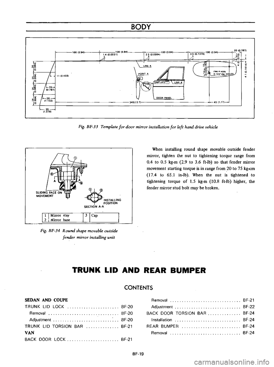
Fig
BF
33
Template
for
door
mirror
installation
for
left
hand
drive
vehicle
INSTALLING
OSITION
SECTION
A
A
When
installing
round
shape
movable
outside
fender
rnirror
tighten
the
nut
to
tightening
torque
range
from
0
4
to
0
5
kg
m
2
9
to
3
6
ft
lb
so
that
fender
rnirror
rnovernent
starting
torque
is
in
range
from
20
to
75
kg
rn
I74
to
65
1
in
lb
When
the
nut
is
tightened
to
tightening
torque
of
1
5
kg
m
10
8
ft
lb
higher
the
fender
mirror
stud
bolt
may
be
broken
Tl4
11
I
Mirror
stay
2
I
Mirror
base
31
Cap
Fig
BF
34
Round
shape
movable
outside
fender
mirror
installing
unit
TRUNK
LID
AND
REAR
BUMPER
CONTENTS
SEDAN
AND
COUPE
TRUNK
LID
LOCK
Removal
Adjustment
TRUNK
LID
TORSION
BAR
VAN
BACK
DOOR
LOCK
BF
20
BF
20
BF
20
BF
21
Removal
Adjustment
BACK
DOOR
TORSION
BAR
Installation
REAR
BUMPER
Removal
BF
21
BF
22
BF
24
BF
24
BF
24
BF
24
BF
21
BF
19
Page 211 of 513
BODY
TRUNK
LID
TORSION
BAR
The
procedures
of
installing
torsion
bar
are
indicated
as
follows
ill
ID
f
Jw
V
@
@
Fig
BF
36
Installing
torsion
bar
1
Closed
position
2
Rotation
center
of
trunk
lid
hinge
3
Trunk
lid
hinge
4
Trunk
lid
torsion
bar
5
Rear
waist
connector
Note
When
installing
the
to
ion
bar
use
to
ion
bar
wrench
special
tool
ST087100001
VAN
t
9
@
i
Fig
BF
37
Back
door
and
hinge
constructions
BACK
DOOR
LOCK
1
Back
door
hinge
torsion
bar
2
Back
door
hinge
3
Back
door
4
Back
door
lock
rod
5
Lock
6
Striker
7
Striker
shim
8
Back
door
side
dovetail
9
Side
dovetail
shim
10
Back
door
bumper
11
Back
door
bumper
plate
Removal
2
Remove
the
lock
cylinder
securing
leaf
clip
so
as
to
free
the
lock
cylinder
and
remove
the
back
door
lock
rod
from
the
lock
cylinder
I
Remove
the
back
door
trim
and
sealing
screen
BF
21
Page 212 of 513

I
1
I
Back
door
lock
rod
I
2
I
Lock
cylinder
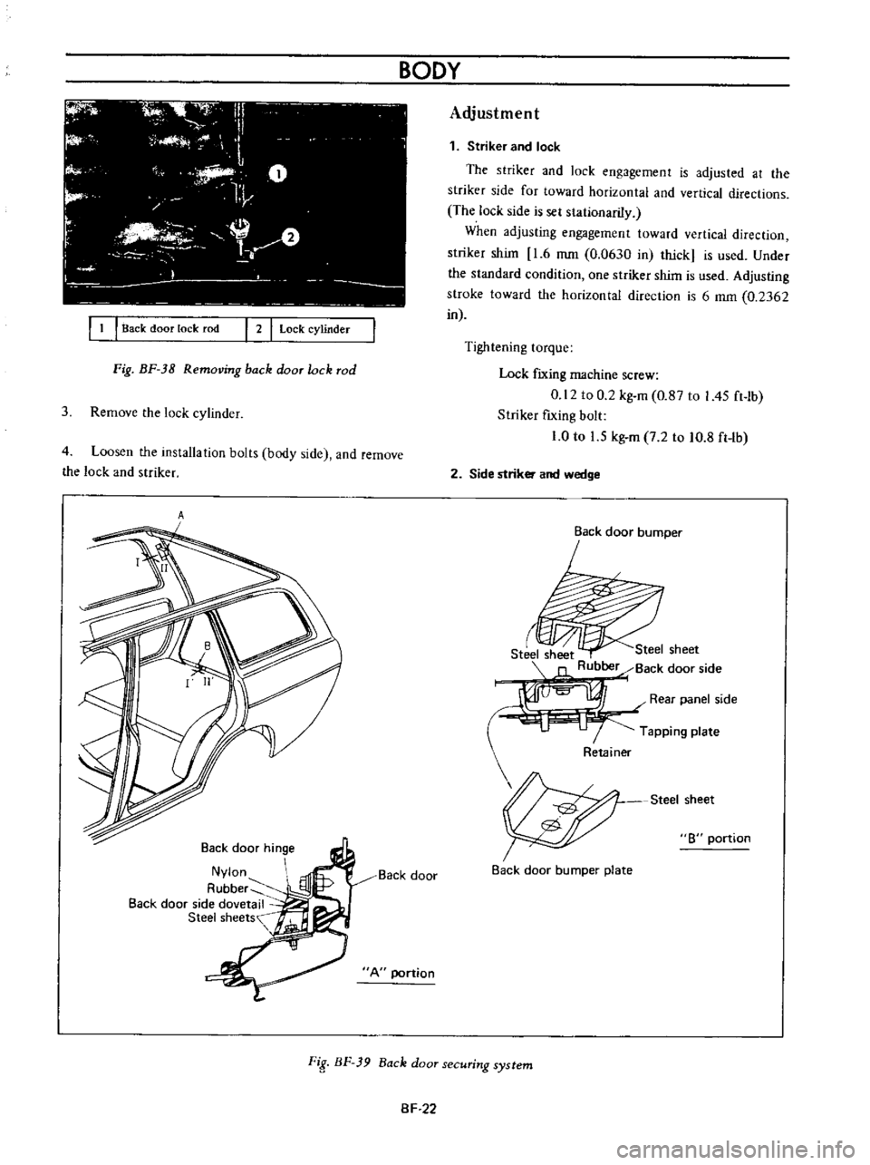
Fig
BF
38
Removing
back
door
lock
rod
3
Remove
the
lock
cylinder
4
Loosen
the
installation
bolts
body
side
and
remove
the
lock
and
striker
A
Back
door
hinge
Nylon
A
ubber
Back
door
side
dovetail
Steel
sheets
Back
door
A
portion
BODY
Adjustment
1
Striker
and
lock
The
striker
and
lock
engagement
is
adjusted
at
the
striker
side
for
toward
horizontal
and
vertical
directions
The
lock
side
is
sel
stationariIy
When
adjusting
engagement
toward
vertical
direction
striker
shim
1
6
mm
0
0630
in
thick
is
used
Under
the
standard
condition
one
striker
shim
is
used
Adjusting
stroke
toward
the
horizontal
direction
is
6
mm
0
2362
in
Tightening
torque
Lock
fIXing
machine
screw
0
12
to
0
2
kg
m
0
87
to
I
45
ft
lb
Striker
fIxing
bolt
1
0
to
1
5
kg
m
7
2
to
10
8
ft
Ib
2
Side
striker
and
wedge
Back
door
bumper
r
Steel
sheet
Steel
sheet
Rubber
Back
door
side
I
Rear
panel
side
Tapping
plate
Steel
sheet
8
portion
Back
door
bumper
plate
FiS
BF
39
Back
door
securing
system
SF
22
Page 214 of 513

BACK
DOOR
TORSION
BAR
BODY
A
D
Installation
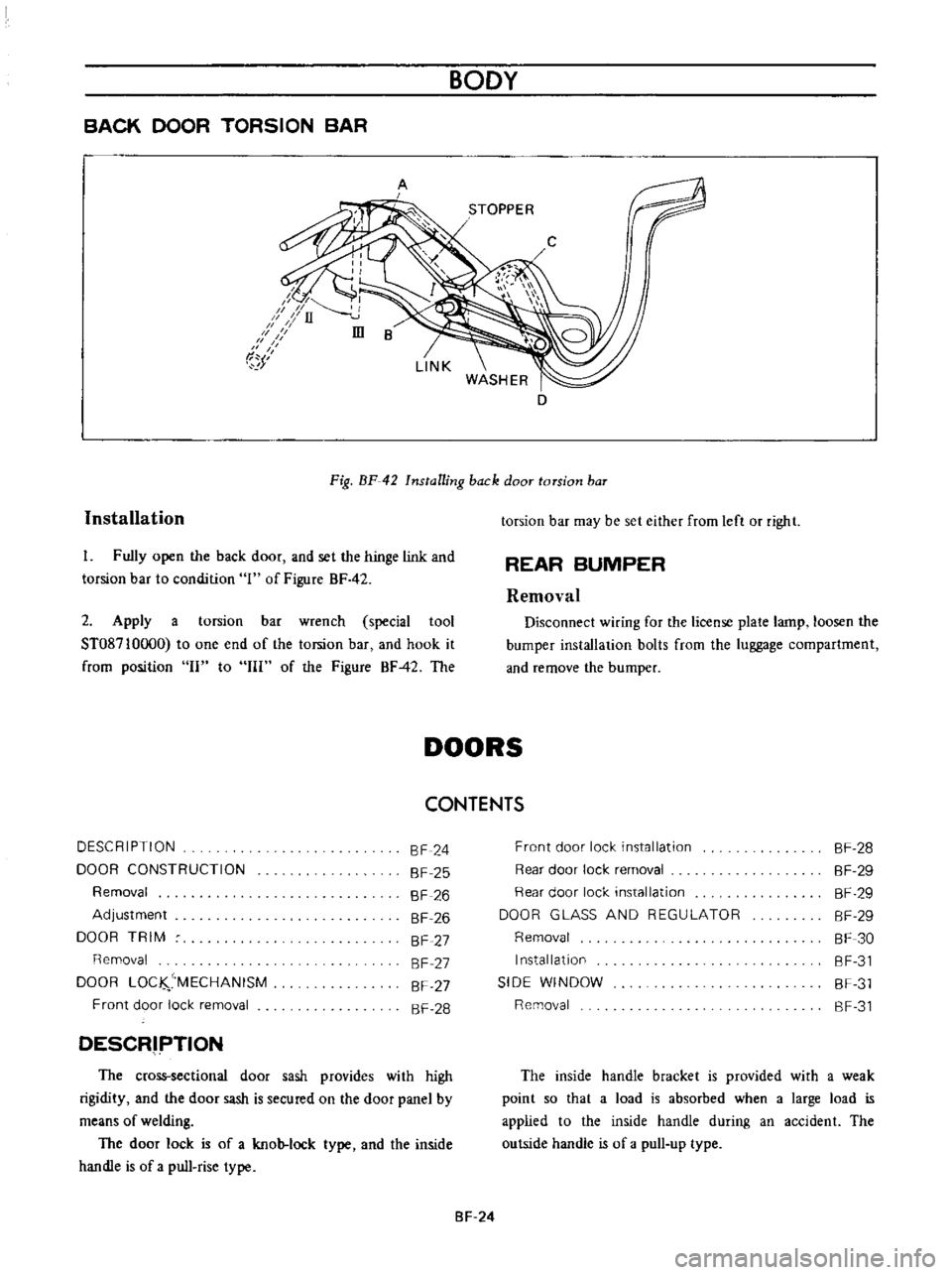
Fig
BF
42
Installing
back
door
torsion
baT
I
Fully
open
the
back
door
and
set
the
hinge
link
and
torsion
bar
to
condition
1
of
Figure
BF
42
2
Apply
a
torsion
bar
wrench
special
tool
ST08710oo0
to
one
end
of
the
torsion
bar
and
hook
it
from
position
II
to
III
of
the
Figure
BF42
The
torsion
bar
may
be
set
either
from
left
or
right
REAR
BUMPER
Removal
Disconnect
wiring
for
the
license
plate
lamp
loosen
the
bumper
installation
bolts
from
the
luggage
compartment
and
remove
the
bumper
DOORS
CONTENTS
DESCRIPTION
DOOR
CONSTRUCTION
Removal
Adjustment
DOOR
TRIM
Removal
DOOR
LOC
MECHANISM
Front
door
lock
removal
SF
24
SF
25
SF
26
SF
26
SF
27
SF
27
SF
27
SF
28
DESCRIPTION
The
cross
sectional
door
sash
provides
with
high
rigidity
and
the
door
sash
is
secured
on
the
door
panel
by
means
of
welding
The
door
lock
is
of
a
knob
lock
type
and
the
inside
handle
is
of
a
pull
rise
type
Front
door
lock
installation
Rear
door
lock
removal
Rear
door
lock
installation
DOOR
GLASS
AND
REGULATOR
Removal
Installation
SIDE
WINDOW
Removal
SF
28
SF
29
SF
29
SF
29
SF
30
SF
31
SF
31
SF
31
The
inside
handle
bracket
is
provided
with
a
weak
point
so
that
a
load
is
absorbed
when
a
large
load
is
applied
to
the
inside
handle
during
an
accident
The
outside
handle
is
of
a
pull
up
type
SF
24
Page 217 of 513
Fig
BF
47
Adjusting
striker
DOOR
TRIM
For
both
the
front
and
rear
doon
the
door
trims
may
be
removed
and
reinsbJled
in
the
same
method
Removal
I
When
removing
the
door
regulator
handle
lock
inside
handle
escutcheon
and
arm
rest
remove
their
installation
screws
2
When
removing
the
ash
tray
outer
case
remove
the
ash
tray
and
remove
the
installation
screws
3
The
door
finish
is
secured
on
the
door
with
clips
When
removing
the
door
finish
pull
it
toward
you
DOOR
LOCK
MECHANISM
BODY
I
I
Regulator
handle
Imide
handle
escu
tcheon
131
Armrest
Fig
BF
48
Door
trim
III
I
2
Outer
case
Ash
tray
Fig
BF
49
Removing
ash
tray
1
1
Door
lock
2
Spring
3
Inside
handle
4
Locking
plate
5
Locking
plate
spring
6
Stopper
7
Outside
handle
8
Ou
tside
handle
rod
9
Nylon
nut
10
Escu
tchcon
11
Knob
grommet
12
Door
lock
knob
13
Door
lock
cylinder
Fig
BF
50
Front
door
lock
mechanism
SF
27
Page 218 of 513

IT
f
r
J
e
@
@
BODY
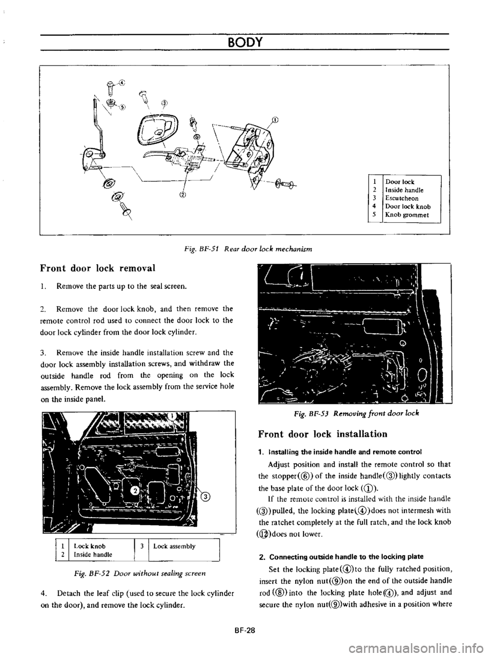
Door
lock
2
I
nside
handle
3
Escu
tcheon
4
Door
lock
knob
5
Knob
grommet
Front
door
lock
removal
Fig
BF
51
Rear
door
lock
mechanism
Remove
the
parts
up
to
the
seal
screen
2
Remove
the
door
lock
knob
and
then
remove
the
remote
control
rod
used
to
connect
the
door
lock
to
the
door
lock
cylinder
from
the
door
lock
cylinder
3
Remove
the
inside
handle
installation
screw
and
the
door
lock
assembly
installation
screws
and
withdraw
the
outside
handle
rod
from
the
opening
on
the
lock
assembly
Remove
the
lock
assembly
from
the
service
hole
on
the
inside
panel
I
I
Lock
knob
Inside
handLe
I
3
I
Lock
assembly
Fig
BF
52
Door
wUhout
sealing
screen
4
Detach
the
leaf
clip
used
to
secure
the
lock
cylinder
on
the
door
and
remove
the
lock
cylinder
Fig
BF
53
Removing
front
door
lock
Front
door
lock
installation
1
Installing
the
inside
handle
and
remote
control
Adjust
position
and
install
the
remote
control
so
that
the
Slopper
@
ofthe
inside
handle
Q
lightly
contacts
the
base
plate
of
the
door
lock
CD
If
the
remote
control
is
installed
with
the
inside
handle
Q
pulled
the
locking
plate
@
doesnotintermesh
with
the
ratchet
completely
at
the
full
ratch
and
the
lock
knob
j
does
not
lower
2
Connecting
outside
handle
to
the
locking
plate
Set
the
locking
plate
@lto
the
fully
ratched
position
insert
the
nylon
nut
@
on
the
end
of
the
outside
handle
rod
ID
into
the
locking
plate
hole
@
and
adjust
and
secure
the
nylon
nut
@
with
adhesive
in
a
position
where
BF
28