1973 DATSUN B110 ignition
[x] Cancel search: ignitionPage 58 of 513
Judgement
in
measurmg
line
pressure
I
Low
idling
line
pressures
in
the
ranges
D
2
loR
and
P
It
can
be
artributed
to
trouble
in
the
pressure
supply
system
or
too
low
output
of
power
caused
by
1
A
worn
oil
pump
2
An
oil
pressure
leakage
in
the
oil
pump
valve
body
or
case
3
A
sticking
regulator
valve
2
Low
idling
line
pressures
in
cer
tain
ranges
only
It
is
caused
pressumabIy
by
an
oil
leakage
in
the
devices
or
circuits
con
nected
to
the
relevant
ranges
1
When
there
is
an
oil
leakage
in
the
rear
clutch
and
governor
the
line
pressures
in
D
2
and
I
are
low
but
the
pressure
is
normal
in
R
2
When
an
oil
leakage
occurs
in
the
low
and
reverse
brake
circuit
the
line
pressures
in
R
and
p
are
low
but
the
pressure
is
normal
in
0
2
and
I
3
High
idling
line
pressures
It
is
presumed
to
be
caused
by
an
increased
vacuum
throttle
pressure
owing
to
a
leakage
in
the
vacuum
tube
or
diaphragm
or
by
an
increased
line
pressure
due
to
a
sticking
regulator
CHASSIS
valve
Vacuum
leakage
is
checked
by
di
reetly
measuring
the
negative
pressure
after
removing
the
vacuum
pipe
A
puncture
of
the
vacuum
dia
phragm
can
be
easily
ascertained
because
the
torque
converter
oil
is
absorbed
into
the
engine
and
the
exhaust
pipe
blows
up
the
white
smoke
4
Checking
items
when
the
line
pressure
is
increasing
In
trJs
checking
the
line
pressure
should
be
measured
with
vacuums
of
450
mmHg
and
0
mmHg
in
accordance
with
the
stall
test
procedure
test
procedure
1
If
the
line
pressures
do
not
increase
despite
the
vacuum
decrease
check
whether
the
vacuum
rod
is
incorporated
2
If
the
line
pressures
do
not
meet
the
standard
it
is
caused
mostly
by
a
sticking
pressure
regulating
valve
pres
sure
regulating
valve
plug
or
amptifier
TROUBLE
SHOOTING
CHART
Inspecting
items
1
Inspection
with
automatic
trans
mission
on
vehicle
J
AT
54
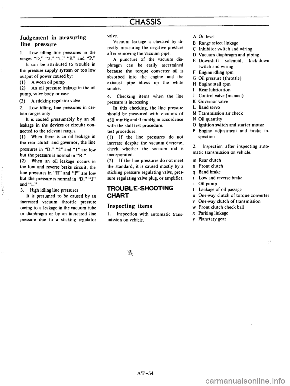
A
Oil
level
B
Range
selecr
linkage
C
Inhibitor
switch
and
wiring
D
Vacuum
diaphragm
and
piping
E
Downshift
solenoid
kick
down
switch
and
wiring
F
Engine
idling
rpm
G
Oil
pressure
throttle
H
Engine
stall
rpm
I
Rear
lubrication
J
Control
valve
manual
K
Governor
valve
L
Band
servo
M
Transmission
air
check
N
Oil
quantity
o
Ignition
switch
and
starter
motor
P
Engine
adjustment
and
brake
in
spection
2
Inspection
after
inspecting
auto
matic
transmission
on
vehicle
m
Rear
clutch
n
Front
clutch
q
Band
brake
r
Low
and
reverse
brake
s
Oil
pump
Leakage
of
oil
passage
u
One
way
clutch
of
torque
converter
v
One
way
clutch
of
transmission
w
Front
clutch
check
ball
x
Parking
linkage
y
Planetary
gear
Page 62 of 513
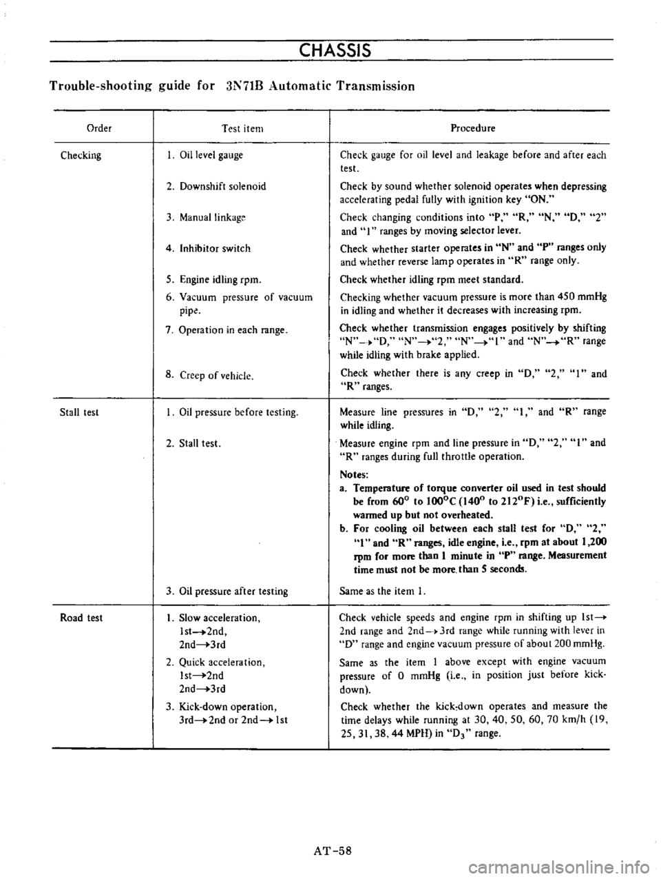
CHASSIS
Trouble
shooting
guide
for
3N71B
Automatic
Transmission
Order
Test
item
Checking
Oil
level
gauge
2
Downshift
solenoid
3
ManuaIlinkage
4
Inhibitor
switch
5
Engine
idling
rpm
6
Vacuum
pressure
of
vacuum
pipe
7
Operation
in
each
range
8
Creep
of
vehicle
Stall
lest
Oil
pressure
before
testing
2
Stall
test
3
Oil
pressure
after
testing
Road
test
Slow
acceleration
Ist
2nd
2nd
3rd
2
Quick
acceleration
Ist
2nd
2nd
3rd
3
Kick
down
operation
3rd
2nd
or
2nd
1st
Procedure
Check
gauge
for
oil
level
and
leakage
before
and
after
each
test
Check
by
sound
whether
solenoid
operates
when
depressing
accelerating
pedal
fully
with
ignition
key
ON
Check
changing
conditions
into
P
R
N
D
2
and
I
ranges
by
moving
selector
lever
Check
whether
starter
operates
in
N
and
tp
ranges
only
and
whether
reverse
lamp
operates
in
R
range
only
Check
whether
idling
rpm
meet
standard
Checking
whether
vacuum
pressure
is
more
than
450
mmHg
in
idling
and
whether
it
decreases
with
increasing
rpm
Check
whether
transmission
engages
positively
by
shifting
N
o
D
N
2
N
I
and
N
R
range
while
idling
with
brake
applied
Check
whether
there
is
any
creep
in
D
2
I
and
R
ranges
2
1
and
R
range
Measure
line
pressures
in
D
while
idling
Measure
engine
rpm
and
line
pressure
in
D
2
I
and
R
ranges
during
fullthrallIe
operation
Notes
a
Temperature
of
torque
converter
oil
used
in
test
should
be
from
600
to
lOOoC
1400
to
2120F
i
e
sufficiently
warmed
up
but
not
overheated
b
For
cooling
oil
between
each
stall
test
for
D
2
1
and
R
ranges
idle
engine
i
e
rpm
at
about
1
200
rpm
for
more
than
1
minute
in
P
range
Measurement
time
must
not
be
more
than
5
secon
Same
as
the
item
I
Check
vehicle
speeds
and
engine
rpm
in
shifting
up
1st
2nd
range
and
2nd
J
3rd
range
while
running
with
lever
in
D
range
and
engine
vacuum
pressure
of
about
200
mmHg
Same
as
the
item
1
above
except
with
engine
vacuum
pressure
of
0
mmHg
i
e
in
position
just
before
kick
down
Check
whether
the
kick
down
operates
and
measure
the
time
delays
while
running
at
30
40
50
60
70
km
h
19
25
31
38
44
MPH
in
D
range
AT
58
Page 223 of 513
BODY
REAR
WINDOW
ELECTRIC
DEFROSTER
Option
J
Instrument
harness
Cooler
terminal
J
1
1
c
BW
Ignition
switch
I
lOA
@
hi
u
Heat
wire
glass
switch
T
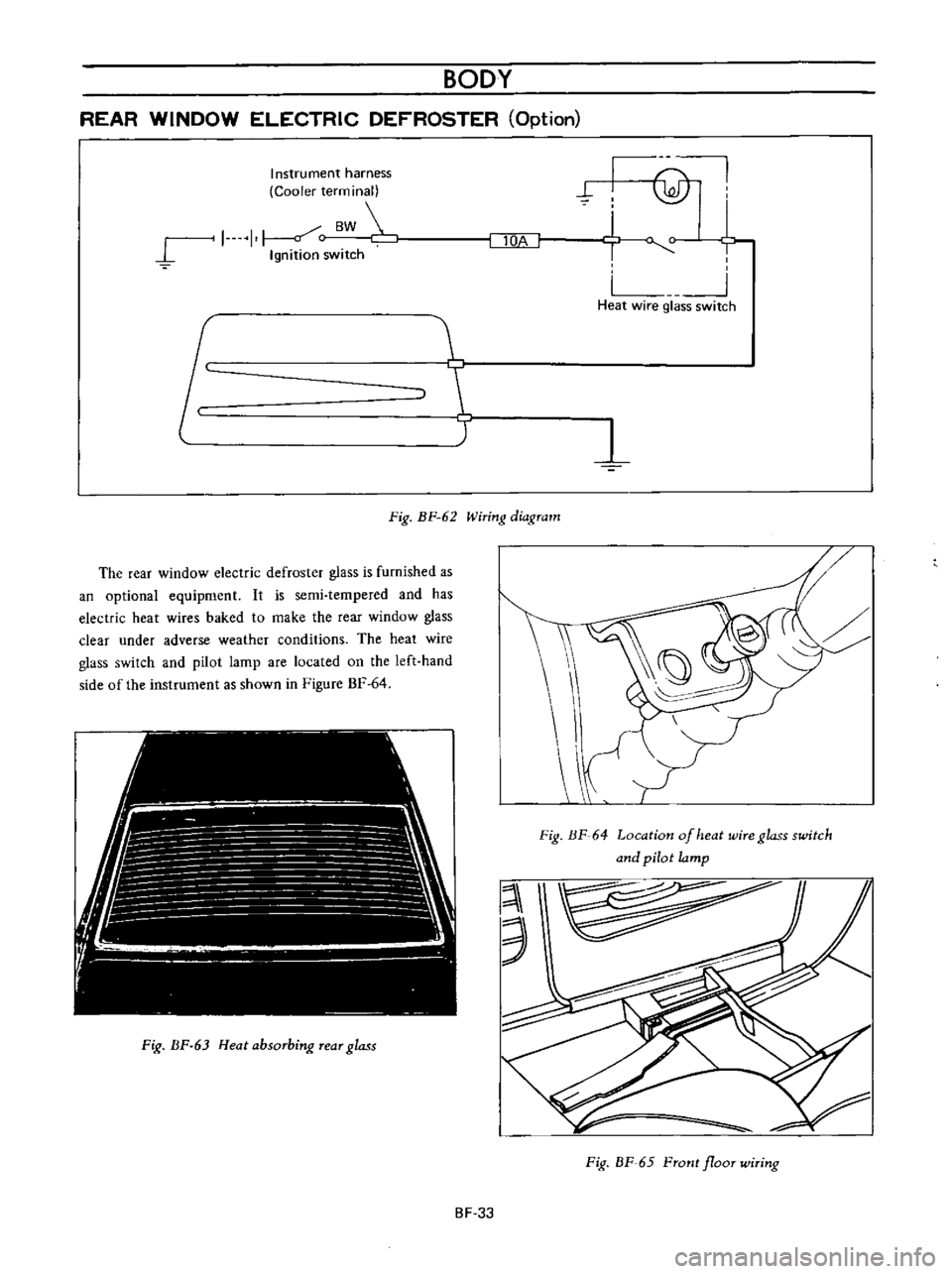
Fig
BF
62
Wiring
diagram
The
rear
window
electric
defroster
glass
is
furnished
as
an
optional
equipment
It
is
semi
tempered
and
has
electric
heat
wires
baked
to
make
the
rear
window
glass
clear
under
adverse
weather
conditions
The
heat
wire
glass
switch
and
pilot
larnp
are
located
on
the
left
hand
side
of
the
instrument
as
shown
in
Figure
BF
64
Fig
BF
63
Heat
absorbing
rear
glass
Fig
HF
64
Location
of
heat
wire
glass
switch
and
pilot
lamp
3
Fig
BF
65
Front
floor
wiring
BF
33
Page 235 of 513
DATSUN
1200
MODEL
B
11
0
SERIES
I
NISSAN
I
NISSAN
MOTOR
CO
LTD
TOKYO
JAPAN
SECTION
BE
BODY
ELECTRICAL
WIRING
FUSE
LIGHTING
SYSTEM
HORN
METERS
AND
GAUGES
WINDSHIELD
WIPER
AND
WASHER
IGNITION
SWITCH
AND
STEERING
LOCK
CLOCK
RADIO
HEATER
BE
1
BE
6
BE
7
BE
15
BE
18
BE
26
BE
29
BE
31
BE
32
BE
34
Page 245 of 513
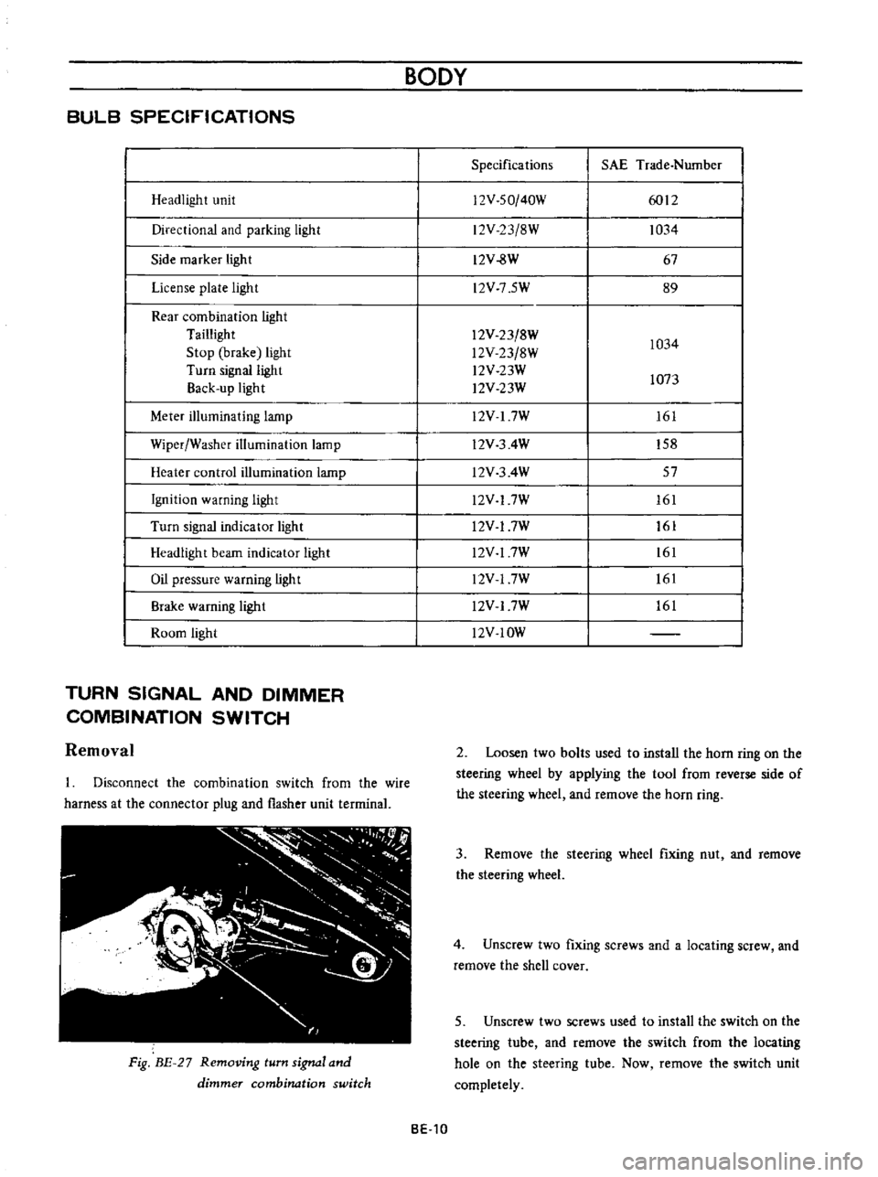
BULB
SPECIFICATIONS
Headlight
unit
Directional
and
parking
light
Side
marker
light
License
plate
light
Rear
combination
light
Taillight
Stop
brake
light
Turn
signal
light
Back
up
light
Meter
illuminating
lamp
Wiper
Washer
illumination
lamp
Heater
control
illumination
lamp
Ignition
warning
light
Turn
signal
indicator
light
Headlight
beam
indicator
light
Oil
pressure
warning
light
Brake
warning
ligh
t
Room
light
TURN
SIGNAL
AND
DIMMER
COMBINATION
SWITCH
Removal
Disconnect
the
combination
switch
from
the
wire
harness
at
the
connector
plug
and
flasher
unit
terrninal
Fig
BE
27
Removing
turn
signal
and
dimmer
combination
switch
BODY
Specifications
SAE
Trade
Number
12V
SO
40W
6012
12V
23
8W
1034
12V
8W
67
l2V
7
5W
89
12V
23
8W
1034
l2V
23
8W
l2V
23W
1073
l2V
23W
12V
I
7W
161
l2V
3
4W
158
l2V
3
4W
57
l2V
17W
161
l2V
17W
161
l2V
17W
161
l2V
17W
161
l2V
17W
161
l2V
IOW
2
Loosen
two
bolts
used
to
install
the
horn
ring
on
the
steering
wheel
by
applying
the
tool
from
reverse
side
of
the
steering
wheel
and
remove
the
horn
ring
3
Remove
the
steering
wheel
fixing
nut
and
remove
the
steering
wheel
4
Unscrew
two
fixing
screws
and
a
locating
screw
and
remove
the
shell
cover
5
Unscrew
two
screws
used
to
install
the
switch
on
the
steering
tube
and
remove
the
switch
from
the
locating
hole
on
the
steering
tube
Now
remove
the
switch
unit
completely
BE
10
Page 246 of 513

BODY
ELECTRICAL
8
G
J
r
ICENSE
LAMPS
10
0
I
I
g
N
Ap
KING
10
00
01
2
I
NATION
J
J
r
j
a
iii
a
g
Lv
F
a
G
G
Lo
o
0
I
I
m
L
J
HER
UNIT
DIMMER
SWITCH
TURN
SIONAl
SWITCH
I
I
Fig
BE
28
Circuit
diagram
for
turn
signal
and
dimmer
switch
system
LIGHTING
SWITCH
HAZARD
WARNING
SWITCH
Removal
The
hazard
lamp
system
4
way
flasher
consists
of
hazard
warning
switch
and
flasher
unit
When
the
hazard
warning
switch
is
turned
on
all
signal
lamps
flash
simultaneously
telling
other
drivers
that
the
vehicle
is
stopped
When
the
turn
signal
lamps
flash
the
pilot
lamps
on
the
instrument
panel
also
flash
telling
you
of
hazard
lamp
operation
1
Rernove
the
connector
from
back
of
the
lighting
switch
2
Depressing
the
lighting
switch
knob
turn
it
counter
clockwise
and
remove
it
3
Loosen
the
escutcheon
switch
frorn
the
cluster
lid
and
remove
the
lighting
IGNITION
SWITCH
EZ
L
I
U
I
JJ
u
HAZARD
UNIT
Ip
FLASHER
UNIT
HAZARD
WARNING
SWITCH
161
6
6
g
Q
a
ll
Zll
Zll
CE
O
a
We
a
l
e
rY
1
LEFT
SiDE
RIGHT
SIDE
Fig
BE
29
Circuit
diagram
for
hazard
lamp
system
BE
11
Page 250 of 513
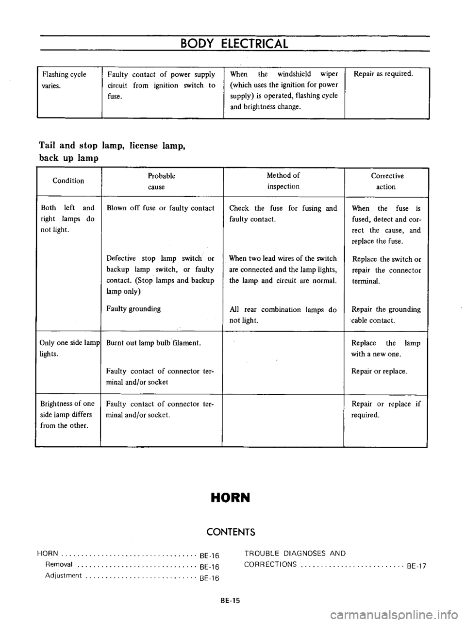
Flashing
cycle
varies
BODY
ELECTRICAL
Faulty
contact
of
power
supply
circuit
from
ignition
switch
to
fuse
Tail
and
stop
lamp
license
lamp
back
up
lamp
Condition
Both
left
and
right
lamps
do
not
light
Probable
cause
Blown
off
fuse
or
faulty
contact
Defective
stop
larnp
switch
or
backup
lamp
switch
or
faulty
contact
Stop
larnps
and
backup
lamp
only
Faulty
grounding
Only
one
side
lamp
Burnt
out
lamp
bulb
f1lament
lights
Brightness
of
one
side
lamp
differs
from
the
other
HORN
Removal
Adjustment
Faulty
contact
of
connector
ter
minal
and
or
socket
Faulty
contact
of
connector
ter
minal
and
or
socket
BE
16
BE
16
BE
16
When
the
windshield
wiper
which
uses
the
ignition
for
power
supply
is
operated
flashing
cycle
and
brightness
change
Method
of
inspection
Check
the
fuse
for
fusing
and
faulty
contact
When
two
lead
wires
of
the
switch
are
connected
and
the
lamp
lights
the
larnp
and
circuit
are
normal
All
rear
combination
lamps
do
not
light
HORN
CONTENTS
TROUBLE
DIAGNOSES
AND
CORRECTIONS
BE
15
Repair
as
required
Corrective
action
When
the
fuse
is
fused
detect
and
COf
rect
the
cause
and
replace
the
fuse
Replace
the
switch
or
repair
the
connector
terrninal
Repair
the
grounding
cable
contact
Replace
the
larnp
with
a
new
one
Repair
or
replace
Repair
or
replace
if
required
BE
17
Page 253 of 513

BODY
METERS
AND
GAUGES
CONTENTS
CLUSTER
LID
Oescri
ption
Removal
SPEEDOMETER
Replacement
FUEL
GAUGE
AND
TEMPERATURE
GAUGE
Description
Replacement
BE
1B
BE
18
BE
18
BE
19
BE
19
BE
19
BE
19
BE
20
CLUSTER
LID
Description
The
cluster
lid
holds
various
rneters
indicators
and
clock
located
around
the
speedorneter
Printed
circuit
board
is
used
at
the
back
of
the
meter
as
shown
in
Figure
BE
38
and
the
printed
circuit
board
is
connected
with
multiple
connectors
Thus
the
meters
Can
be
inspected
and
serviced
extremely
easily
Except
for
the
speed
ometer
all
rneters
are
operated
electrically
The
fuel
gauge
and
therrnometer
are
very
reliable
and
they
are
equipped
with
bimetal
devices
F
a
o
ill
I
1
a
a
Fig
BE
34
Combination
meters
Removal
Disconnect
the
battery
terminal
depressing
the
OIL
PRESSURE
AND
IGNITION
WARNING
LAMPS
HAND
BRAKE
WARNING
LAMP
BULB
SPECIFICATIONS
TROUBLE
DIAGNOSES
AND
CORRECTIONS
Speedometer
Thermometer
and
fuel
meter
Oil
pressure
and
ignition
warning
lamps
BE
20
BE
21
BE
21
BE
22
BE
22
BE
23
BE
25
windshield
wiper
switch
lighting
switch
and
choke
lever
knobs
turn
them
counterclockwise
to
remove
Remove
the
escutcheon
2
Inserting
your
hand
into
back
of
the
cluster
lid
disconnect
the
cigarette
lighter
cable
and
turn
and
remove
the
cigarette
lighter
outer
case
3
Remove
the
radio
and
heater
control
knobs
4
Remove
the
shell
cover
from
the
steering
tube
loosen
the
screws
used
to
secure
the
meter
housing
to
the
instrument
panel
and
remove
the
cluster
lid
5
Pull
out
the
l2
pole
round
shape
connector
and
remove
the
speedometer
cable
union
nut
6
Remove
the
cluster
lid
from
the
instrument
panel
Fig
BE
35
Removing
clllSter
jd
BE
18