1973 DATSUN B110 width
[x] Cancel search: widthPage 79 of 513
CHASSIS
7
Turn
drive
pinion
in
both
directions
several
times
to
set
bearing
rollers
And
adjust
bearing
preload
to
specifi
cations
Drive
pinion
bearing
preload
with
oil
seal
7
to
9
kg
cm
6
1
to
7
8
in
1b
At
companion
flange
bolt
hole
2
25
to
2
95
kg
4
96
to
6
50
1b
Pinion
nut
tightening
torque
12
to
17
kg
m
86
8
to
122
9
ft
1b
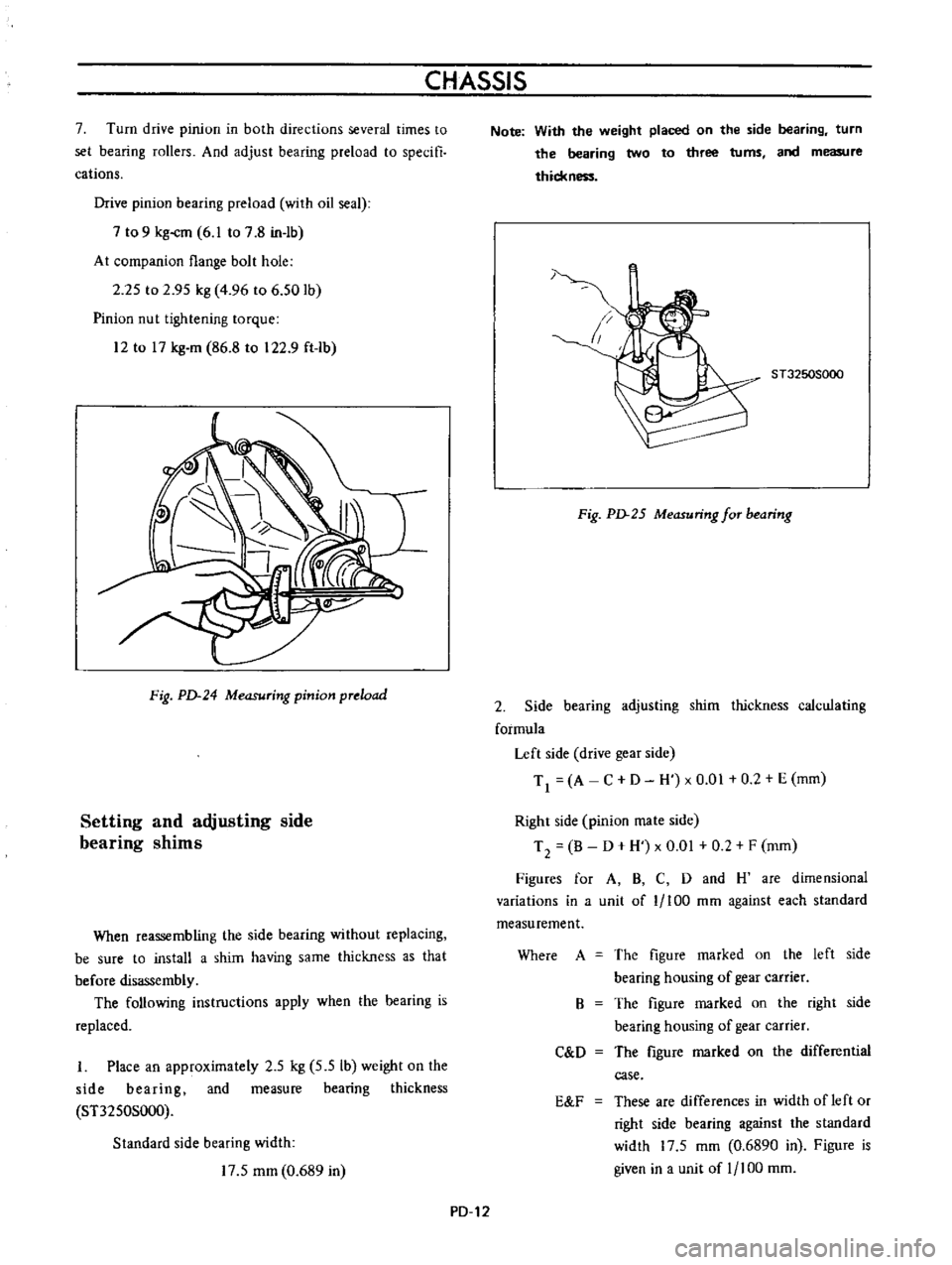
Fig
PD
24
Measuring
pinion
preload
Setting
and
adjusting
side
bearing
shims
When
reassembling
the
side
bearing
without
replacing
be
sure
to
install
a
shim
having
same
thickness
as
that
before
disassembly
The
following
instructions
apply
when
the
hearing
is
replaced
I
Place
an
approximately
2
5
kg
5
5
Ib
weight
on
the
side
bearing
and
measure
bearing
thickness
ST3250S000
Standard
side
bearing
width
17
5
mm
0
689
in
Note
With
the
weight
placed
on
the
side
bearing
turn
the
bearing
two
to
three
turns
and
measure
thickn
1
ST3250S000
Fig
PD
25
Measuring
for
bearing
2
Side
bearing
adjusting
shim
thickness
calculating
formula
Left
side
drive
gear
side
Tl
A
C
D
H
xO
01
0
2
E
mm
Right
side
pinion
mate
side
T
2
B
D
H
x
0
01
0
2
F
mm
Figures
for
A
B
C
D
and
H
are
dimensional
variations
in
a
unit
of
1
100
mm
against
each
standard
measurement
Where
A
The
figure
marked
on
the
left
side
bearing
housing
of
gear
carrier
The
figure
marked
on
the
right
side
bearing
housing
of
gear
carrier
The
figure
marked
on
the
differential
case
B
C
D
E
F
These
are
differences
in
width
of
left
or
right
side
bearing
against
the
standard
width
17
5
mm
0
6890
in
Figure
is
given
in
a
unit
of
1
100
mm
PD
12
Page 85 of 513
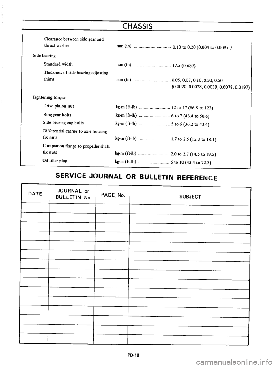
Clearance
between
side
gear
and
thrust
washer
CHASSIS
rrun
in
0
10
to
0
20
0
004
to
0
008
Side
bearing
Standard
width
rom
in
Thickness
of
side
bearing
adjusting
shims
rom
in
Tightening
torque
Drive
pinion
nut
Ring
gear
bolts
Side
bearing
cap
bolts
Differential
carrier
to
axle
housing
fIx
nuts
Companion
flange
to
propeller
shaft
fIx
nuts
Oil
filler
plug
17
5
0
689
0
05
0
07
0
10
0
20
0
50
0
0020
0
0028
0
0039
0
0078
0
0197
kg
m
ft
lb
kg
m
ft
lb
kg
m
ft
lb
12
to
17
86
8
to
123
6
to
7
43
4
to
50
6
5
to
6
36
2
to
43
4
kg
m
ft
1b
17
to
2
5
12
3
to
18
1
kg
m
ft
lb
kg
m
ft
lb
2
0
to
2
7
14
5
to
19
5
6
to
10
43
4
to
72
3
SERVICE
JOURNAL
OR
BULLETIN
REFERENCE
DATE
JOURNAL
or
BULLETIN
No
I
I
I
I
PAGE
No
SUBJECT
PO
1S
Page 147 of 513
BRAKE
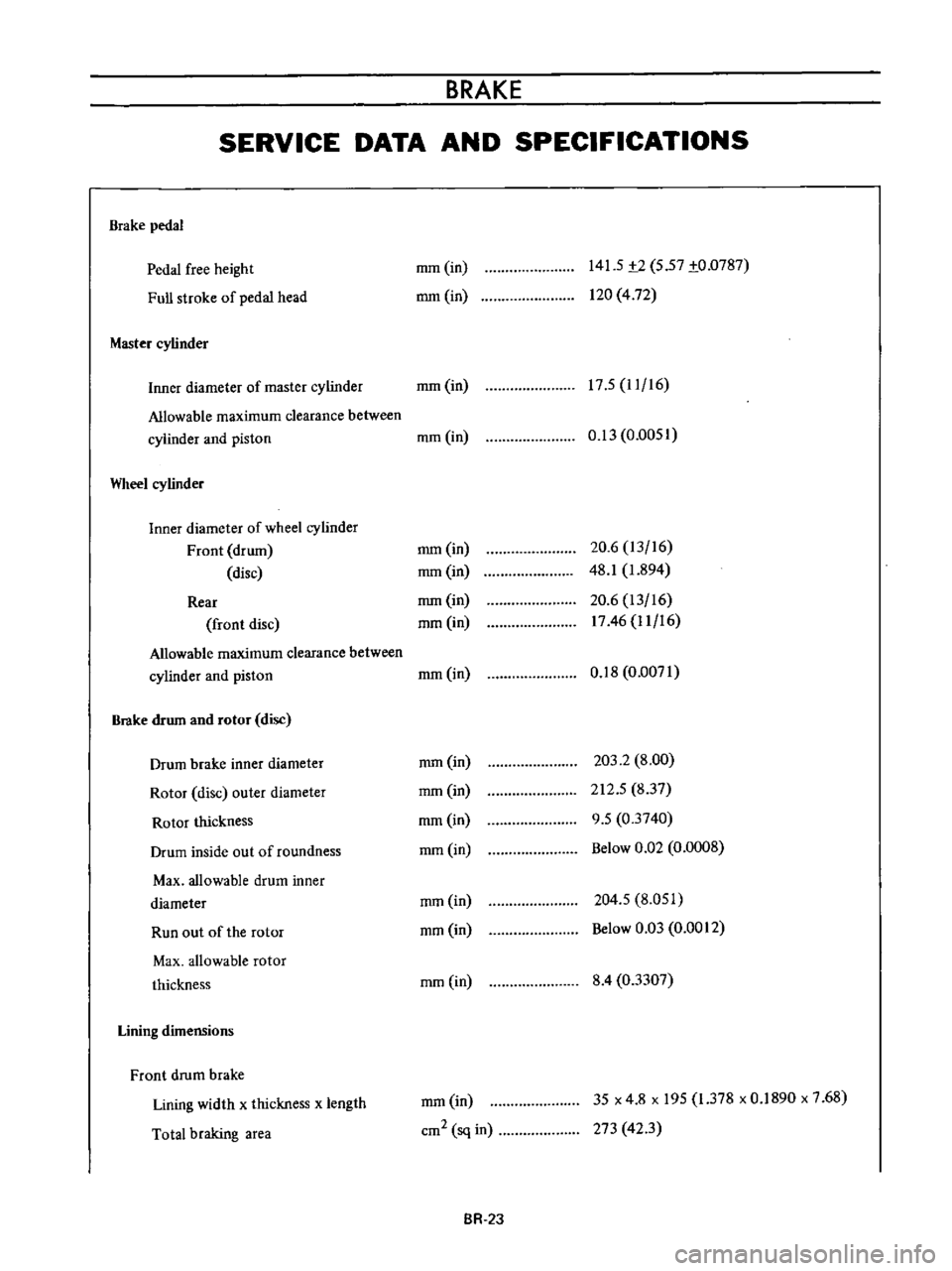
SERVICE
DATA
AND
SPECIFICATIONS
Brake
pedal
Pedal
free
height
Full
stroke
of
pedal
head
Master
cylinder
mm
in
mm
in
141
5
t2
5
57
to
0787
120
4
72
17
5
11
16
Inner
diameter
of
master
cylinder
mm
in
Allowable
maximum
clearance
between
cylinder
and
piston
mm
in
Wheel
cylinder
Inner
diameter
of
wheel
cylinder
Front
drum
disc
Rear
front
disc
Allowable
maximum
clearance
between
cylinder
and
piston
Brake
drum
and
rotor
disc
Drum
brake
inner
diameter
Rotor
disc
outer
diameter
Rotor
thickness
Drum
inside
out
of
roundness
Max
allowable
drum
inner
diameter
Run
out
of
the
rotor
Max
allowable
rotor
thickness
Lining
dimensions
Front
drum
brake
Lining
width
x
thickness
x
length
Total
braking
area
0
13
0
0051
mm
in
mm
in
mm
in
mm
in
20
6
13
16
48
1
1
894
20
6
13
16
1746
11
16
mm
in
0
18
0
0071
mm
in
mm
in
mm
in
mm
in
203
2
8
00
212
5
837
9
5
03740
Below
0
Q2
0
0008
mm
in
mm
in
204
5
8
051
Below
0
03
0
0012
mm
in
8
4
03307
mm
in
cm2
sq
in
35
x
4
8
x
195
1
378
x
0
1890
x
7
68
273
423
BR
2J
Page 148 of 513
Lining
material
Front
disc
brake
Pad
width
x
thickness
x
length
Total
braking
area
Rear
brake
Lining
width
x
thickness
x
length
Total
braking
area
Tightening
torque
Brake
pedal
fulcrum
pin
Master
cylinder
installation
bolt
Brake
tube
installation
flare
nut
Rear
brake
hose
and
connector
installation
nut
Front
wheel
cylinder
installation
bolt
Brake
warning
switch
installation
bolt
Front
brake
disc
installation
bolt
Caliper
assembly
installation
bolt
Rear
brake
adjuster
installation
bolt
Hand
brake
cable
hanger
strap
installation
bolt
Hand
brake
lever
installation
bolt
Rotor
and
hub
installation
bolt
CHASSIS
mm
in
cm2
sq
in
mm
in
cm2
sq
in
kg
m
ft
1b
kg
m
ft
lb
kg
m
ft
lb
kg
m
ft
lb
kg
m
ft
lb
kg
m
ft
lb
kg
m
ft
lb
kg
m
ft
lb
kg
m
ft
lb
kg
m
ft
lb
kg
m
ft
lb
kg
m
ft
Ib
B40
Akebuno
make
42
5
x
10
3
x
53
I
1
673
x
0
406
x
2
091
90
3
14
0
35
x
4
8
x
195
1
378
x
0
1890
x
7
68
273
42
3
2
0
to
3
0
11
6
to
217
2
1
to
2
9
15
2
to
21
0
1
5
to
1
8
l
0
8
to
13
0
1
5
to
1
8
10
8
to
13
0
a
0
5
to
0
7
3
6
to
5
I
b
1
6
to
2
2
I
1
6
to
15
9
0
32
to
0
44
2
31
to
3
18
2
7
to
3
7
19
5
to
26
8
4
6
to
6
1
33
3
to
44
1
1
6
to
2
2
11
6
to
15
9
0
32
to
0
44
2
31
to
3
18
1
0
to
I
4
7
23
to
10
1
44
to
59
31
8
to
42
7
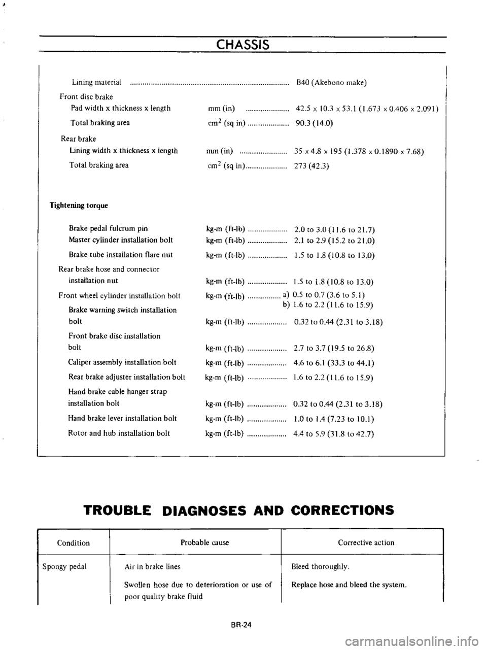
TROUBLE
DIAGNOSES
AND
CORRECTIONS
Condition
Spongy
pedal
Air
in
brake
lines
Probable
cause
Swollen
hose
due
to
deterioration
or
use
of
poor
quality
brake
fluid
BR
24
Corrective
action
Bleed
thoroughly
Replace
hose
and
bleed
the
system
Page 224 of 513
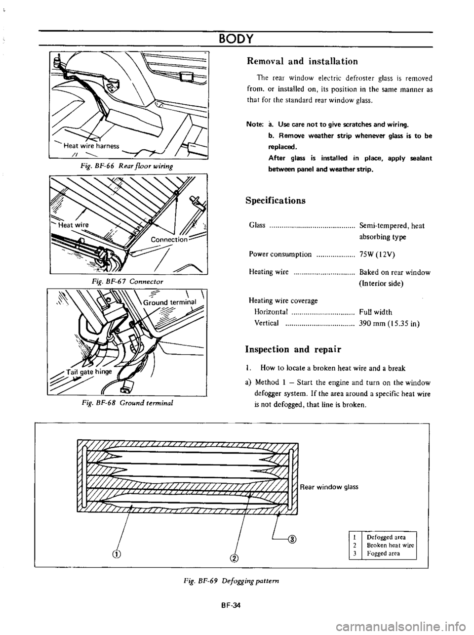
BODY
Removal
and
installation
The
rear
window
electric
defroster
glass
is
removed
from
or
installed
on
its
position
in
the
same
manner
as
that
for
the
standard
rear
window
glass
Heat
wire
harness
1
Fig
BF
66
Rear
floor
wiring
Note
a
Use
care
not
to
give
scratches
and
wiring
b
Remove
weather
strip
whenever
glass
is
to
be
replaced
After
glass
is
installed
in
place
apply
sealant
between
panel
and
weather
strip
1
Connection
Specifications
Glass
Semi
tempered
heat
absorbing
type
Power
consumption
75W
l2V
Heating
wire
Baked
on
rear
window
Interior
side
Heating
wire
coverage
Horizontal
Vertical
Full
width
390
mm
15
35
in
Inspection
and
repair
Ground
terminal
How
to
locate
a
broken
heat
wire
and
a
break
a
Method
I
Start
the
engine
and
turn
on
the
window
defogger
system
If
the
area
around
a
specific
heat
wire
is
not
defogged
that
line
is
broken
n
if
U
i
p
w
w
j
w
j
fj
f
i
j
L
1
2
Defogged
area
Broken
heat
wire
Fogged
area
Fig
BF
69
Defogging
pattern
BF
34
Page 280 of 513
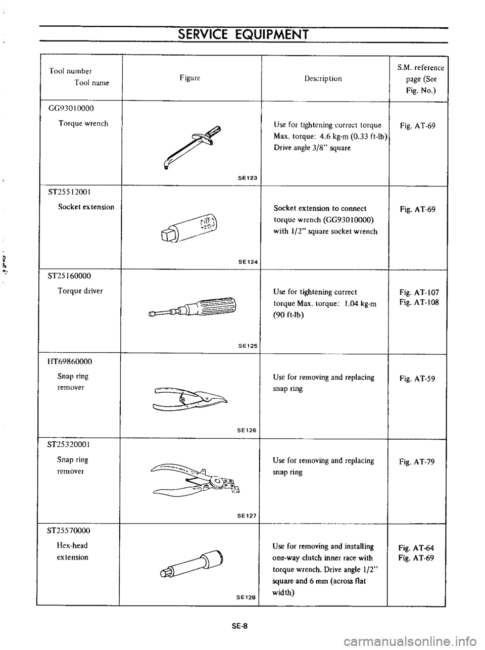
SERVICE
EQUIPMENT
Tool
number
S
M
reference
Tool
name
Figure
Description
page
See
Fig
No
GG930
10000
Torque
wrench
Use
for
tightening
correct
torque
Fig
A
T
69
Max
torque
4
6
kg
m
0
33
ft
lb
Drive
angle
3
8
square
SE123
ST255
12001
Socket
extension
Socket
extension
to
connect
Fig
A
T
69
0
torque
wrench
GG930
I
000
with
1
2
square
socket
wrench
SE124
ST25
160000
Torque
driver
Use
for
tightening
correct
Fig
AT
107
torque
Max
torque
1
04
kg
m
Fig
AT
108
u
90
ft
Ib
SE125
HT69860000
Snap
ring
Use
for
removing
and
replacing
Fig
AT
59
remover
snap
ring
SE126
ST25320001
Snap
ring
Use
for
removing
and
replacing
Fig
AT
79
snap
ring
remover
Go
O
SE127
ST25570000
Hex
head
Use
for
removing
and
installing
Fig
AT
64
extension
one
way
clutch
inner
race
with
Fig
AT
69
torque
wrench
Drive
angle
1
2
square
and
6
mm
across
flat
SE128
width
sE
8
Page 284 of 513
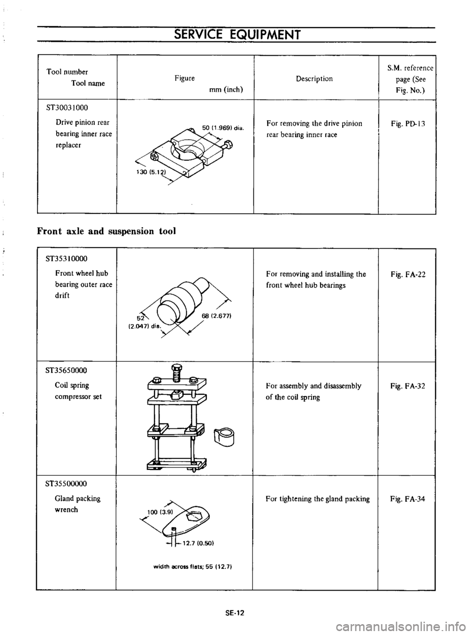
Tool
number
Tool
name
ST30031000
Drive
pinion
rear
bearing
inner
race
replacer
SERVICE
EQUIPMENT
Figure
mm
inch
Front
axle
and
suspension
tool
ST353
10000
Front
wheel
hub
bearing
outer
race
drift
ST35650000
Coil
spring
compressor
set
ST35500000
Gland
packing
wrench
rU
jb
1118
1
1
width
across
flats
55
12
71
SE
12
Descrip
tion
For
removing
the
drive
pinion
rear
bearing
inner
race
For
removing
and
installing
the
front
wheel
hub
bearings
For
assembly
and
disassembly
of
the
coil
spring
For
tightening
the
gland
packing
S
M
reference
page
See
Fig
No
Fig
PD
13
Fig
FA
22
Fig
FA
32
Fig
FA
34
Page 361 of 513
ENGINE
MECHANICAL
Standard
Maximum
Crankshaft
bend
mm
in
0
05
0
0020
0
015
0
0006
Note
When
measuring
bend
use
a
dial
gauge
Bend
value
is
a
half
of
the
reading
obtained
when
the
crankshaft
is
turned
once
with
the
dial
gauge
applied
to
its
center
journal
3
After
regrinding
the
crankshaft
fmish
it
to
the
necessary
size
indicated
in
the
lists
on
pages
EM
25
by
using
an
adequate
undersize
bearing
according
to
the
extent
of
required
repair
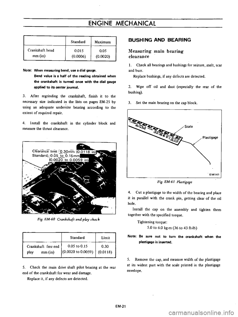
4
Install
the
crankshaft
in
the
cylinder
block
and
measure
the
thrust
clearance
Fig
EM
60
Crankshaft
end
pldy
check
Standard
Limit
Crankshaft
free
end
play
rom
in
0
05
to
0
15
0
0020
to
0
0059
0
30
0
D118
5
Check
the
main
drive
shaft
pilot
bearing
at
the
rear
end
of
the
crankshaft
for
wear
and
damage
Replace
it
if
any
defects
are
detected
BUSHING
AND
BEARING
Measuring
main
bearing
clearance
Check
all
bearings
and
bushings
for
seizure
melt
scar
and
burr
Replace
bushings
if
any
defects
are
detected
2
Wipe
off
oil
and
dust
especially
the
rear
of
the
bushing
3
Set
the
main
bearing
on
the
cap
block
Scale
Plastigage
EM141
Fig
EM
61
Plastigage
4
Cut
a
plastigage
to
the
width
of
the
bearing
and
place
it
in
parallel
with
the
crank
pin
getting
clear
of
the
oil
hole
Install
the
cap
on
the
assembly
and
tighten
them
together
with
the
specified
torque
Tightening
torque
5
0
to
6
0
kg
m
36
to
43
ft
lb
Note
Be
sure
not
to
turn
the
crankshaft
when
the
plastigage
is
inserted
5
Remove
the
cap
and
measure
width
of
the
plastigage
at
its
widest
part
with
the
scale
printed
in
the
plastigage
envelope
EM
21