1973 DATSUN B110 air suspension
[x] Cancel search: air suspensionPage 107 of 513
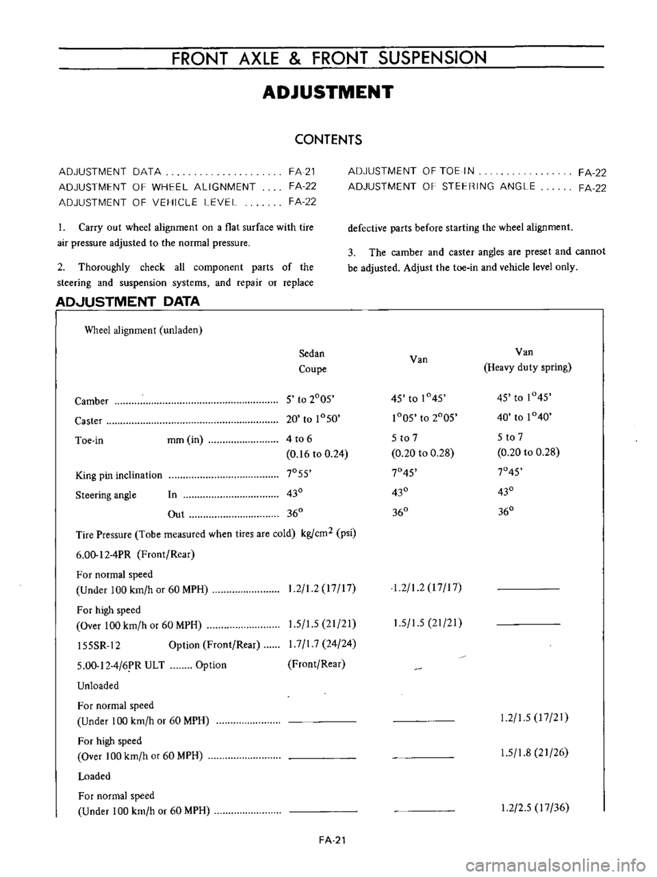
FRONT
AXLE
FRONT
SUSPENSION
ADJUSTMENT
CONTENTS
ADJUSTMENT
DATA
ADJUSTMENT
OF
WHEEL
ALIGNMENT
ADJUSTMENT
OF
VEHICLE
LEVEL
FA
21
FA
22
FA
22
1
Carry
out
wheel
alignment
on
a
flat
surface
with
tire
air
pressure
adjusted
to
the
normal
pressure
2
Thoroughly
check
all
component
parts
of
the
steering
and
suspension
systems
and
repair
or
replace
AD
JUSTMENT
DATA
I
Wheel
alignment
unladen
Sedan
Coupe
Camber
5
to
2005
Caster
20
to
1050
Toe
in
mm
in
4
to
6
0
16
to
0
24
King
pin
inclination
7055
Steering
angle
In
430
Out
360
Tire
Pressure
Tobe
measured
when
tires
are
cold
kgfcm2
psi
6
00
12
4PR
Front
Rear
For
normal
speed
Under
100
km
h
or
60
MPH
For
high
speed
Over
100
km
h
or
60
MPH
15SSR
12
Option
Front
Rear
1
2
1
2
17
17
1
5
1
5
21
21
I
7
I
7
24
24
Front
Rear
5
00
12
4
6
R
ULT
Unloaded
Option
For
normal
speed
Under
100
km
h
or
60
MPH
For
high
speed
Over
100
km
h
or
60
MPH
Loaded
For
normal
speed
Under
100
km
h
or
60
MPH
FA
21
ADJUSTMENT
OF
TOE
IN
ADJUSTMENT
OF
STEERING
ANGLE
FA
22
FA
22
defective
parts
before
starting
the
wheel
alignment
3
The
camber
and
caster
angles
are
preset
and
cannot
be
adjusted
Adjust
the
toe
in
and
vehicle
level
only
Van
Van
Heavy
duty
spring
45
to
1045
45
to
1045
1005
to
2005
40
to
1040
5
to
7
5
to
7
0
20
to
0
28
0
20
to
0
28
7045
7045
430
430
360
360
1
2
1
2
I
7
I
7
1
5
1
5
21
21
1
2
1
5
17
21
1
5
1
8
21
26
1
2
2
5
17
36
Page 111 of 513
FRONT
AXLE
FRONT
SUSPENSION
joint
Transverse
link
mounting
bolt
Tension
rod
Transverse
link
side
Body
side
Stabilizer
bar
Connecting
rod
and
transverse
link
installation
nut
Connecting
rod
and
stabilizer
bar
installation
nut
Stabilizer
bar
and
body
installation
bolt
2
2
to
3
0
15
9
to
21
7
4
0
to
5
0
28
9
to
36
2
2
2
to
3
0
15
9
to
217
5
5
to
6
5
39
7
to
47
0
0
9
to
1
2
6
5
to
8
7
0
9
to
1
2
6
5
to
8
7
0
9
to
1
2
6
5
to
8
7
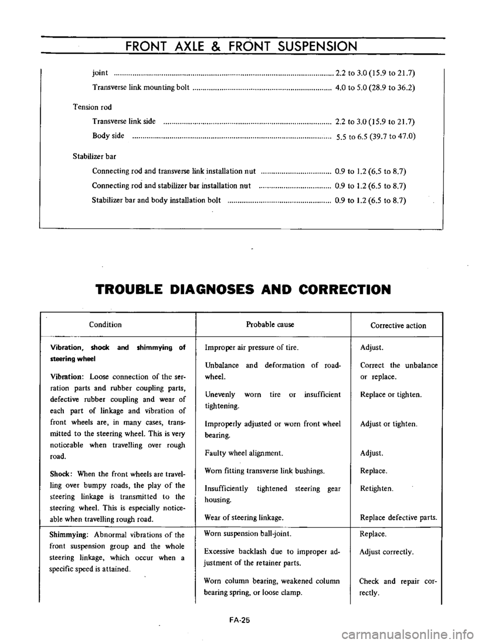
TROUBLE
DIAGNOSES
AND
CORRECTION
Condition
Vibration
shock
and
shimmying
of
steering
wheel
Vibmtion
Loose
connection
of
the
ser
ration
parts
and
rubber
coupling
parts
defective
rubber
coupling
and
wear
of
each
part
of
linkage
and
vibration
of
front
wheels
are
in
many
cases
trans
mitted
to
the
steering
wheeL
This
is
very
noticeable
when
travelling
over
rough
road
Shock
When
the
front
wheels
are
travel
ling
over
bumpy
roads
the
play
of
the
steering
linkage
is
transmitted
to
the
steering
wheeL
This
is
especially
notice
able
when
travelling
rough
road
Shimmying
Abnormal
vibrations
of
the
front
suspension
group
and
the
whole
steering
linkage
which
occur
when
a
specific
speed
is
attained
Probable
cause
Improper
air
pressure
of
tire
Unbalance
and
deformation
of
road
wheeL
Unevenly
worn
tire
or
insufficient
tightening
Improperly
adjusted
or
worn
front
wheel
bearing
Faulty
wheel
alignment
Worn
fitting
transverse
link
bushings
Insufficiently
tightened
steering
gear
housing
Wear
of
steering
linkage
Worn
suspension
ball
joint
Excessive
backlash
due
to
improper
ad
justment
of
the
retainer
parts
Worn
column
bearing
weakened
column
bearing
spring
or
loose
clamp
FA
25
Corrective
action
Adjust
Correct
the
unbalance
or
replace
Replace
or
tighten
Adjust
or
tighten
Adjust
Replace
Retighten
Replace
defective
parts
Replace
Adjust
correctly
Check
and
repair
cor
rectly
Page 112 of 513
Vehicle
pulls
to
right
or
left
When
driving
with
hands
off
the
steering
wheel
over
a
flat
road
the
vehicle
gently
swerves
to
right
or
left
Note
A
defective
rear
suspension
may
also
be
the
cause
of
this
trouble
and
therefore
see
also
the
chapter
dealing
with
the
rear
suspension
Instability
of
vehicle
Stiff
steering
wheel
checking
up
procedure
Jack
up
front
wheels
detach
the
steering
gear
and
operate
the
steering
wheel
and
If
it
is
light
check
steering
linkage
and
suspension
groups
If
it
is
heavy
check
steering
gear
and
steering
colunm
groups
CHASSIS
Malfunction
of
shock
absorber
inside
the
strut
or
loose
installation
bolts
Unbalance
of
vehicle
level
Improper
air
pressure
of
tire
or
insuf
ficient
tightening
of
wheel
nuts
Difference
in
height
of
right
and
left
tire
treads
Incorrect
adjustment
or
abrasion
of
front
wheel
bearing
Collapsed
or
twisted
front
spring
Incorrect
wheel
alignment
Incorrect
brake
adjustment
binding
Worn
rubber
bushings
for
transverse
link
and
tension
rod
Deformed
steering
linkage
and
suspension
link
Unbalanced
vehicle
level
Improper
air
pressure
of
tire
Worn
rubber
bushings
for
transverse
link
and
tension
rod
Incorrect
wheel
alignment
Worn
or
deformed
steering
linkage
and
suspension
link
Incorrect
adjustment
of
steering
gear
Deformed
unbalanced
wheel
Improper
air
pressure
of
tire
Insufficient
lubricants
or
mixing
im
purities
in
steering
linkage
or
excessively
worn
steering
linkage
Stiff
or
damaged
suspension
ball
joint
or
lack
of
grease
Worn
or
incorrectly
adjusted
wheel
bearing
Worn
damaged
steering
gear
and
bearing
FA
26
Replace
or
retighten
Correct
the
unbalance
Adjust
or
tighten
Replace
tires
Adjust
or
replace
Replace
Adjust
Adjust
Replace
Replace
Correct
the
unbalance
Adjust
Adjust
Adjust
Replace
Adjust
Correct
or
replace
Adjust
Repl
nish
grease
or
re
place
the
part
Replace
Replace
or
adjust
Replace
Page 113 of 513
FRONT
AXLE
FRONT
SUSPENSION
Incorrectly
adjusted
steering
gear
Deformed
steering
linkage
Incorrect
wheel
alignment
Damaged
strut
upper
end
bearing
Damaged
or
stiff
piston
or
shock
absorber
rod
in
the
strut
Interference
of
steering
column
with
turn
signal
switch
Excessive
steering
wheel
play
Noises
Grating
tire
noise
Incorrectly
adjusted
steering
gear
housing
Worn
steering
linkage
Improperly
fitted
gear
box
Incorrectly
adjusted
wheel
bearing
Worn
transverse
link
and
tension
rod
fitting
bushings
Improper
air
pressure
of
tire
Insufficient
lubricating
oil
and
grease
for
suspension
ball
joint
and
steering
linkage
or
their
breakage
Loose
steering
gear
bolts
linkage
and
suspension
groups
Defective
shock
absorber
inside
the
strut
Defective
wheel
bearing
Worn
steering
linkage
Worn
transverse
link
and
tension
rod
fitting
bushings
Broken
collapsed
coil
spring
Loose
strut
mounting
insulator
tightening
nuts
Improper
air
pressure
of
tire
Incorrect
wheel
alignment
Deformed
knuckle
spindle
and
suspension
linkage
FA
27
Adjust
Replace
Adjust
Replace
Replace
Adjust
Adjust
Replace
Retighlen
Adjust
Replace
Adjust
Replenish
lubrication
oil
and
grease
or
re
place
Retighten
Replace
Replace
Replace
Replace
Replace
Retighten
Adjust
Adjust
Replace
Page 119 of 513
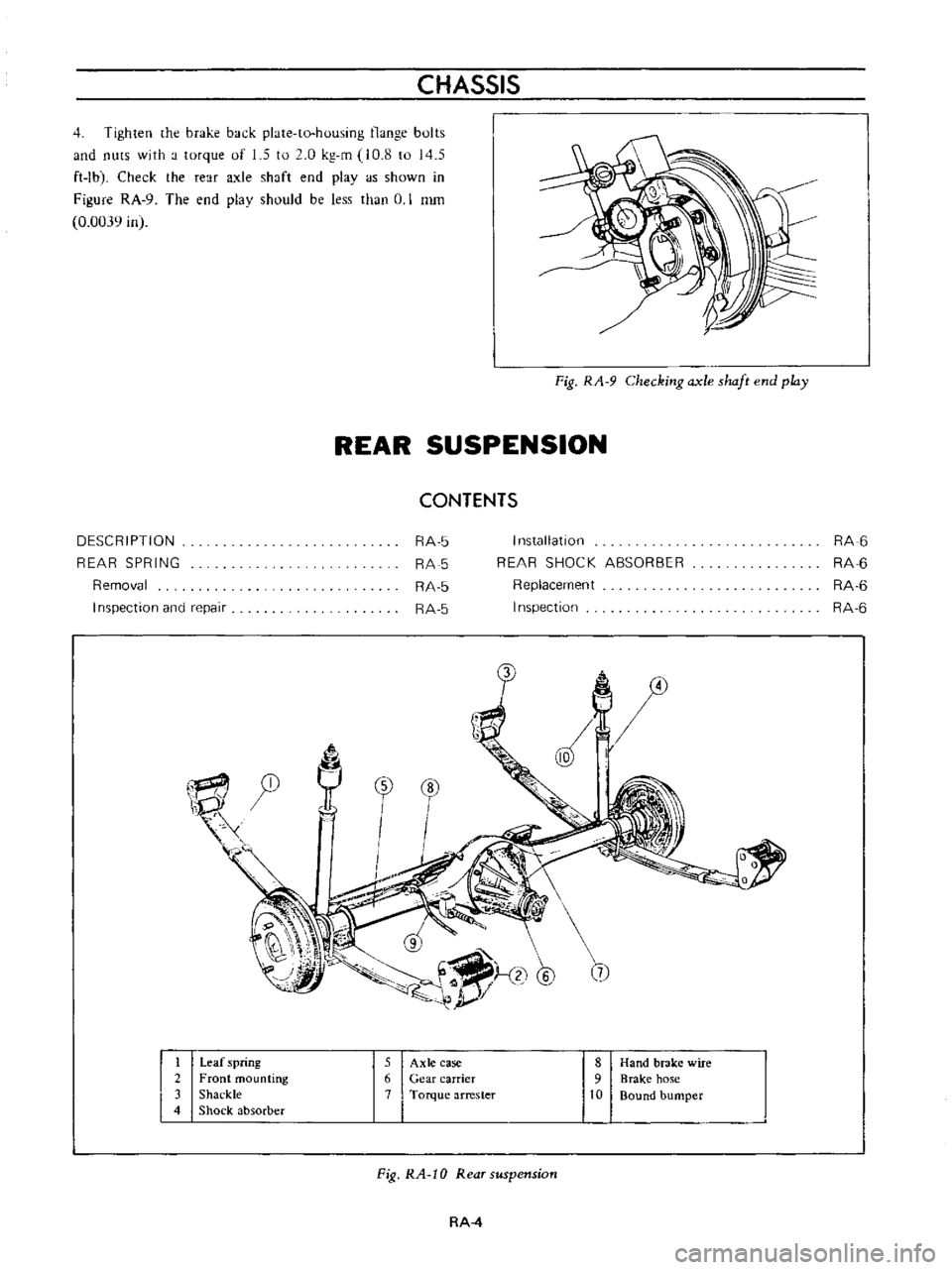
CHASSIS
4
Tighten
he
brake
back
plate
to
housing
nunge
bults
and
nuts
with
a
torque
of
1
5
to
2
0
kg
m
10
8
to
145
ft
Ibl
Check
the
rear
axle
shaft
end
playas
shown
in
Figure
RA
9
The
end
plav
should
be
less
than
U
I
nun
0
0039
in
Fig
RA
9
Checking
axle
shaft
end
play
REAR
SUSPENSION
CONTENTS
DESCRIPTION
REAR
SPRING
Removal
I
nspection
and
repair
RA
5
RA
5
RA
5
RA
5
I
n5tallatlon
REAR
SHOCK
ABSORBER
Replacement
Inspection
RA
6
RA
6
RA
6
RA
6
0
tr
1
1
@
5
@
7
I
Leaf
spring
5
Axle
case
8
Hand
brake
wire
2
Front
mounting
6
Gear
carrier
9
Brake
hose
3
Shackle
7
Torque
arrester
10
Bound
bumper
4
Shock
absorber
Fig
RA
10
Rear
suspension
RA
4
Page 120 of 513
REAR
AXLE
REAR
SUSPENSION
DESCRIPTION
Rear
suspension
consists
of
semi
elliptic
leaf
springs
telescopic
hydraulic
shock
absorbers
and
rubber
bumpers
The
rear
spring
center
pin
is
off
set
110
mm
4
33
in
toward
the
front
from
the
center
of
the
spring
This
is
done
to
reduce
spring
wind
up
and
to
decrease
the
arc
while
the
rear
wheel
swings
through
Thereby
minimizing
the
possibility
of
the
rear
suspension
effecting
vehicle
stability
Iso
clamp
devices
are
used
for
attaching
the
axle
housing
to
the
spring
The
leaf
springs
shock
absorbers
and
rear
axle
housing
are
mounted
on
rubber
bushings
at
each
end
to
minimize
noise
and
vibration
of
the
transmission
to
the
car
body
and
passenger
compartment
REAR
SPRING
Removal
1
Jack
up
the
center
of
the
rear
axle
until
the
wheels
are
clear
from
the
ground
Support
the
rear
end
of
the
frame
on
stands
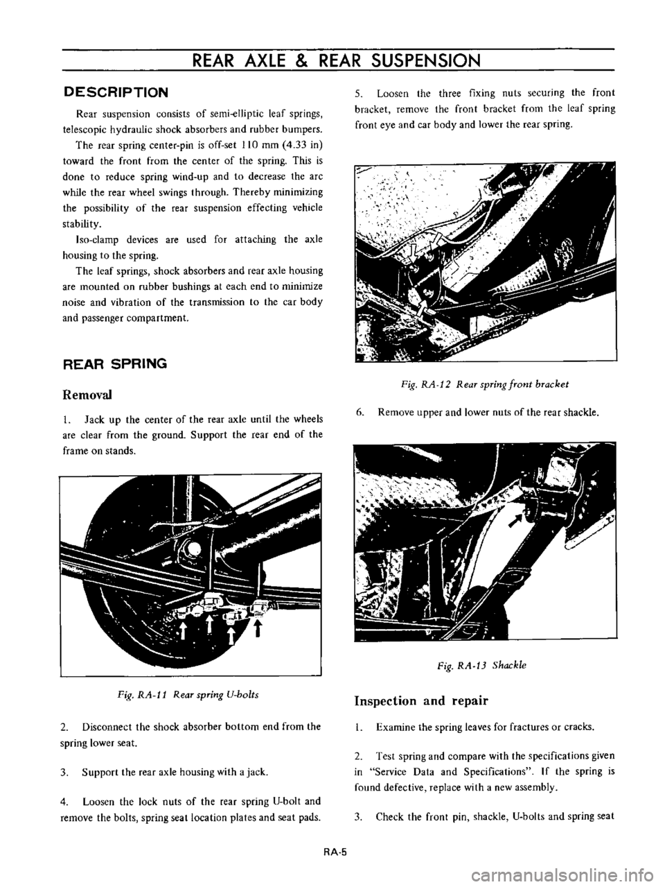
Fig
RA
l1
Rear
spring
U
bo
ts
2
Disconnect
the
shock
absorber
bottom
end
from
the
spring
lower
seat
3
Support
the
rear
axle
housing
with
a
jack
4
Loosen
the
lock
nuts
of
the
rear
spring
U
bolt
and
remove
the
bolts
spring
seat
location
plates
and
seat
pads
5
Loosen
the
three
fixing
nuts
securing
the
front
bracket
remove
the
front
bracket
from
the
leaf
spring
front
eye
and
car
body
and
lower
the
rear
spring
Fig
RA
12
Rear
spring
front
bracket
6
Remove
upper
and
lower
nuts
of
the
rear
shackle
Fig
RA
13
Shackle
Inspection
and
repair
1
Examine
the
spring
leaves
for
fractures
or
cracks
2
Test
spring
and
compare
with
the
specifications
given
in
Service
Data
and
Specifications
If
the
spring
is
found
defective
replace
with
a
new
assembly
3
Check
the
front
pin
shackle
U
bolts
and
spring
seat
RA
5
Page 130 of 513
CHASSIS
1
I
Front
3
way
connector
I
2
I
Brake
master
cylinder
I
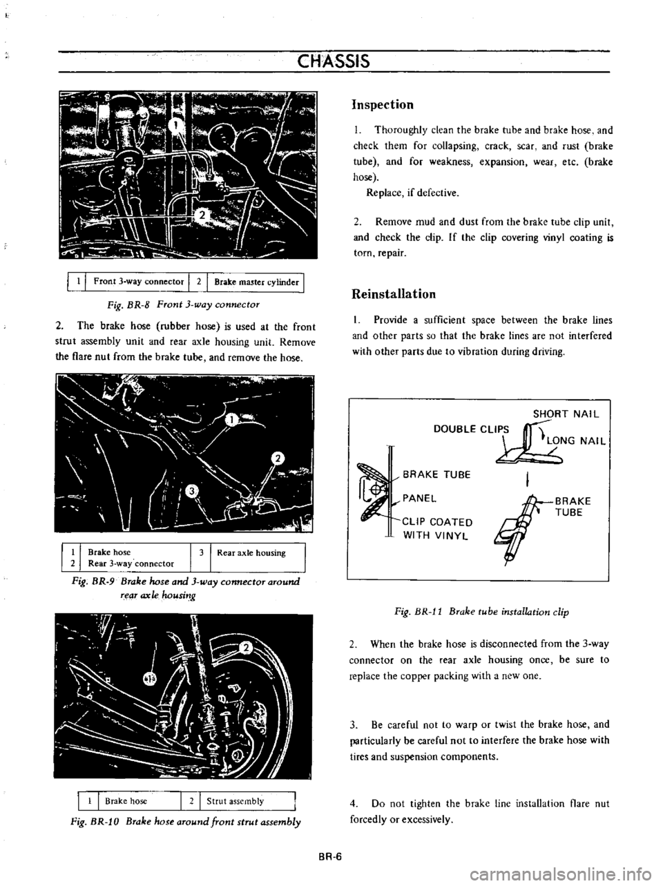
Fig
BR
8
Front
3
way
connector
2
The
brake
hose
rubber
hose
is
used
at
the
front
strut
assembly
unit
and
fear
axle
housing
unit
Remove
the
flare
nut
from
the
brake
tube
and
remove
the
hose
I
r
I
I
l
j
u
l
I
J
II
V
r
1
0
l
I
l
I
I
Brake
hose
I
3
I
Rear
axle
hOUSing
2
Rear
3
way
connector
Fig
BR
9
Brake
hose
and
3
way
connector
around
rear
ax
Ie
housi
g
1
1
Brake
hose
I
2
I
Strut
assembly
Fig
BR
J
0
Brake
hose
around
front
strut
assembly
Inspection
L
Thoroughly
clean
the
brake
tube
and
brake
hose
and
check
them
for
collapsing
crack
scar
and
rust
brake
tube
and
for
weakness
expansion
wear
etc
brake
hose
Replace
if
defective
2
Remove
mud
and
dust
from
the
brake
tube
clip
unit
and
check
the
clip
If
the
clip
covering
vinyl
coating
is
torn
repair
Reinstallation
1
Provide
a
sufficient
space
between
the
brake
lines
and
other
parts
so
that
the
brake
lines
are
not
interfered
with
other
parts
due
to
vibration
during
driving
SHORT
NAIL
DOUBLECLI
S
t
LONG
NAI
L
BRAKE
TUBE
PANEL
CLIP
COATED
WITH
VINYL
BRAKE
TUBE
Fig
BR
l1
Brake
tube
installation
clip
2
When
the
brake
hose
is
disconnected
from
the
3
way
connector
on
the
rear
axle
housing
once
be
sure
to
replace
the
copper
packing
with
a
new
one
3
Be
careful
not
to
warp
or
twist
the
brake
hose
and
particularly
be
careful
not
to
interfere
the
brake
hose
with
tires
and
suspension
components
4
Do
not
tighten
the
brake
line
installation
flare
nut
forcedly
or
excessively
BR
6
Page 156 of 513
WHEEL
AND
TIRE
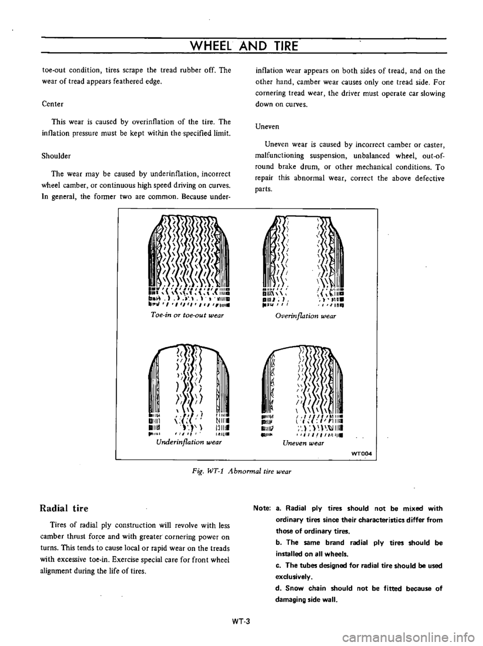
toe
out
condition
tires
scrape
the
tread
rubber
off
The
wear
of
tread
appears
feathered
edge
Center
This
wear
is
caused
by
overinllation
of
the
tire
The
inllation
pressure
must
be
kept
within
the
specified
limit
Shoulder
The
wear
may
be
caused
by
underinflation
incorrect
wheel
camber
or
continuous
high
speed
driving
on
curves
n
general
the
former
two
are
common
Because
under
I
I
I
I
1
1111
I
r
r
m
1
J
11
tHlla
tJ
I
1
1
1
I
1
Ull
Toe
in
aT
toe
au
t
wear
l
f
I
II
I
I
I
I
Ill
Ill
Underinflation
wear
I
11
01
DIIII
II
1
11111
NIII
13111
inflation
wear
appears
on
both
sides
of
tread
and
on
the
other
hand
camber
wear
causes
only
one
tread
side
For
cornering
tread
wear
the
driver
must
operate
car
slowing
down
on
curves
Uneven
Uneven
wear
is
caused
by
incorrect
camber
or
caster
malfunctioning
suspension
unbalanced
wheel
out
of
round
brake
drum
or
other
mechanical
conditions
To
repair
this
abnormal
wear
correct
the
above
defective
parts
Ii
I
I
I
I
1
i
f
I
I
I
I
I
III
I
I
11
DlIIn
ilia
pml
H
IlLl
11111
Overinflation
wear
1D1I1
d
II
1I111
II
j
J
1
51
I
I
I
1
il
I
I
II
l
f
I
11
11111
I
IIIII
i
1
iI
1111111
Uneven
wear
f
I
I
u
WT004
Fig
WT
1
Abnonnal
tire
wear
Radial
tire
Tires
of
radial
ply
construction
will
revolve
with
less
camber
thrust
force
and
with
greater
cornering
power
on
turns
This
tends
to
cause
local
or
rapid
wear
on
the
treads
with
excessive
toe
in
Exercise
special
care
for
front
wheel
alignment
during
the
life
of
tires
Note
a
Radial
ply
tires
should
not
be
mixed
with
ordinary
tires
since
their
characteristics
differ
from
those
of
ordinary
tires
b
The
same
brand
radial
ply
tires
should
be
installed
on
all
wheels
c
The
tubes
designed
for
radial
tire
should
be
used
exclusively
d
Snow
chain
should
not
be
fitted
because
of
damaging
side
wall
WT3