Page 158 of 513
WHEEL
AND
TIRE
Note
In
replacing
tire
take
extra
care
not
to
damage
tire
bead
rim
flange
and
bead
seat
Do
not
use
tire
irons
to
force
beads
away
from
wheel
rim
flange
that
is
always
use
tire
replace
ment
device
whenever
tire
is
removed
WT005
2
Discard
when
any
of
the
following
trouble
occurs
I
Broken
or
damaged
bead
wire
2
Ply
or
tread
separation
3
Worn
febric
damage
on
tubeless
tire
4
Cracked
or
damaged
side
wall
etc
Fig
WT
4
Wheel
rim
run
out
heck
points
TROUBLE
DIAGNOSES
AND
CORRECTIONS
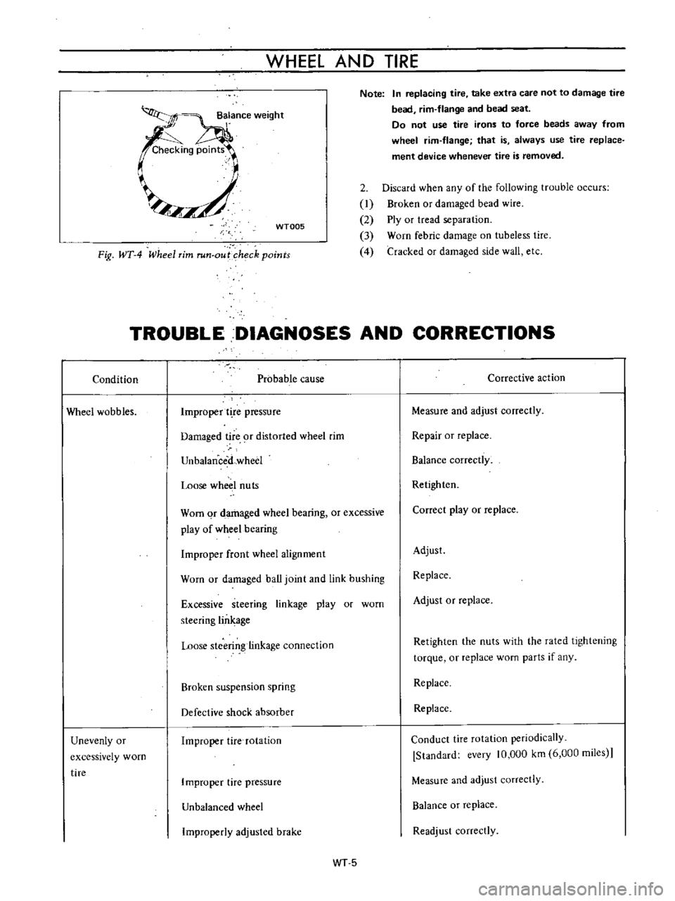
Condition
Probable
cause
Corrective
action
Wheel
wobbles
Improper
t
re
pressure
Measure
and
adjust
correctly
Damaged
tire
9f
distorted
wheel
rim
Repair
or
replace
UnbalanceiLwheel
Balance
correctly
Loose
wheel
nuts
Retighten
Worn
qr
damaged
wheel
bearing
or
excessive
play
of
wheel
bearing
Correct
play
or
replace
Improper
front
wheel
alignment
Adjust
Worn
or
damaged
ball
joint
and
link
bushing
Replace
Excessive
steering
linkage
play
or
worn
steering
lin
age
Adjust
or
replace
Loose
stcerin
linkage
connection
Retighten
the
nuts
with
the
rated
lightening
torque
or
replace
worn
parts
if
any
Broken
suspension
spring
Replace
Defective
shock
absorber
Replace
Unevenly
or
excessively
worn
tire
Improper
tire
rotation
Conduct
tire
rotation
periodically
Standard
every
10
000
km
6
000
miies
Improper
tire
pressure
Measure
and
adjust
correctly
Unbalanced
wheel
Balance
or
replace
Improperly
adjusled
brake
Readjust
correctly
WT5
Page 159 of 513
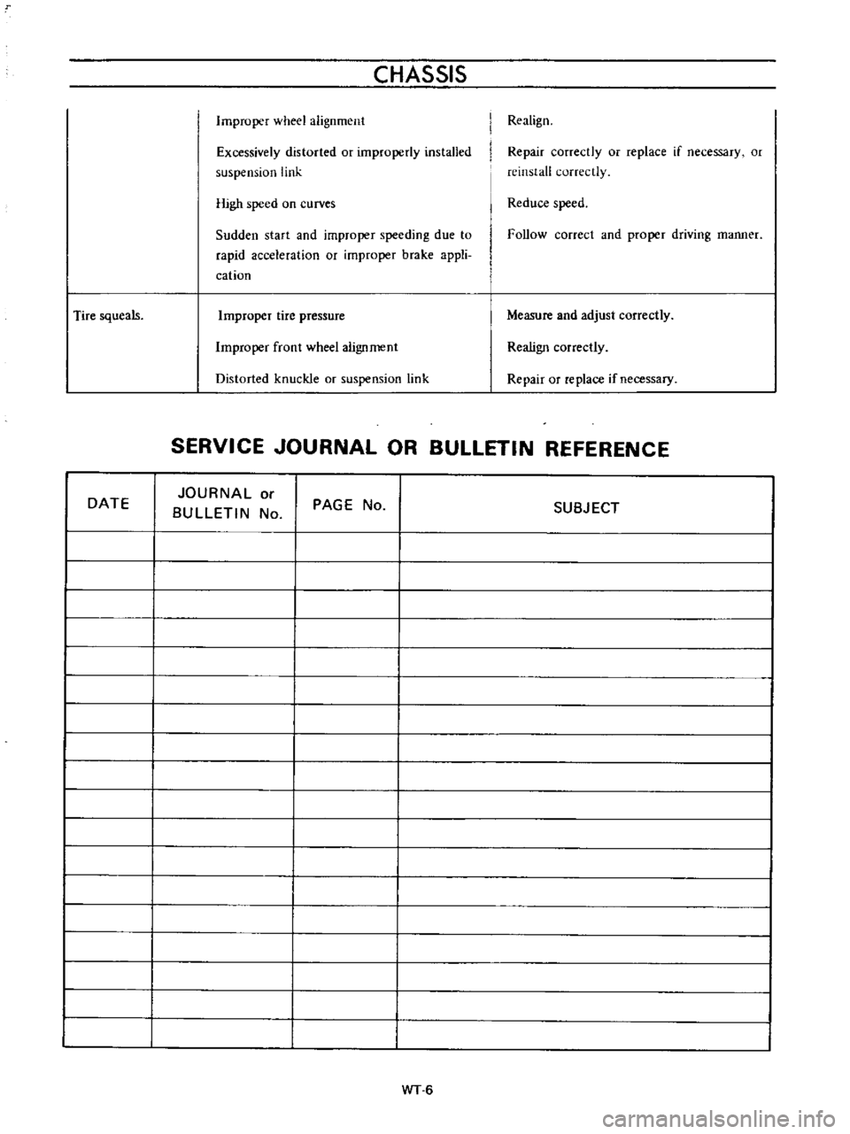
Tire
squeals
DATE
CHASSIS
Improper
wheel
alignment
Excessively
distorted
or
improperly
installed
suspension
link
High
speed
on
curves
Sudden
start
and
improper
speeding
due
to
rapid
acceleration
or
improper
brake
appli
cation
Improper
tire
pressure
Improper
front
wheel
alignment
Distorted
knuckle
or
suspension
link
Realign
Repair
correctly
or
replace
if
necessary
or
reinstall
correctly
Reduce
speed
Follow
correct
and
proper
driving
manner
Measure
and
adjust
correctly
Realign
correctly
Repair
or
replace
if
necessary
SERVICE
JOURNAL
OR
BULLETIN
REFERENCE
JOURNAL
or
BULLETIN
No
PAGE
No
I
I
I
I
I
I
I
I
I
I
I
I
I
I
I
I
I
I
WT
6
SUBJECT
Page 199 of 513
BODY
UNDERBODY
ALIGNMENT
CONTENTS
UNDERBODY
GENERAL
SERVICE
INFORMATION
ALIGNMENT
CHECKING
PROCEDURE
BF
9
BF
9
UNDERBODY
GENERAL
SERVICE
INFORMATION
Since
each
underbody
component
directly
affects
the
overall
strength
of
the
body
it
is
essential
that
proper
welding
sealing
and
rust
proofing
techniques
be
observed
during
service
operations
Whenever
the
body
is
repaired
be
sure
to
provide
the
repaired
body
parts
with
rust
proof
In
the
case
of
a
rust
proofmg
critical
underbody
component
it
is
essential
that
a
good
quality
type
air
dry
primer
such
as
corrosion
resistant
zinc
chromate
be
used
Do
not
use
combination
type
primer
surfacers
ALIGNMENT
CHECKING
PROCEDURE
Misalignment
in
the
underbody
affects
the
front
fender
door
trunk
lid
and
window
alignments
and
also
the
tail
gate
and
rear
body
opening
alignments
in
the
case
of
a
station
wagon
or
van
Underbody
misalignment
particularly
affects
the
suspension
system
thereby
causing
various
problems
that
arise
from
suspension
misalignment
It
is
essential
that
underbody
components
be
aligned
within
the
specified
dimensions
given
in
Figures
BF
13
14
and
IS
In
the
event
of
collision
damage
it
is
important
that
underbody
a1ignrnent
be
thoroughly
checked
and
if
necessary
realigned
to
the
specified
dirnensions
There
are
many
tools
that
may
be
ernployed
to
correct
collision
damage
such
as
frame
straightening
machines
external
pulling
equipment
other
standard
body
jacks
PRINCIPLES
OF
TRAMMING
CAR
PREPARATION
TRAMMING
SEQUENCE
BF
9
BF
10
BF
10
To
assist
in
checking
alignment
of
the
underbody
components
repairing
minor
underbody
damage
or
locating
replacement
parts
the
following
underbody
dimensions
and
alignment
checking
information
are
presented
PRINCIPLES
OF
TRAMMING
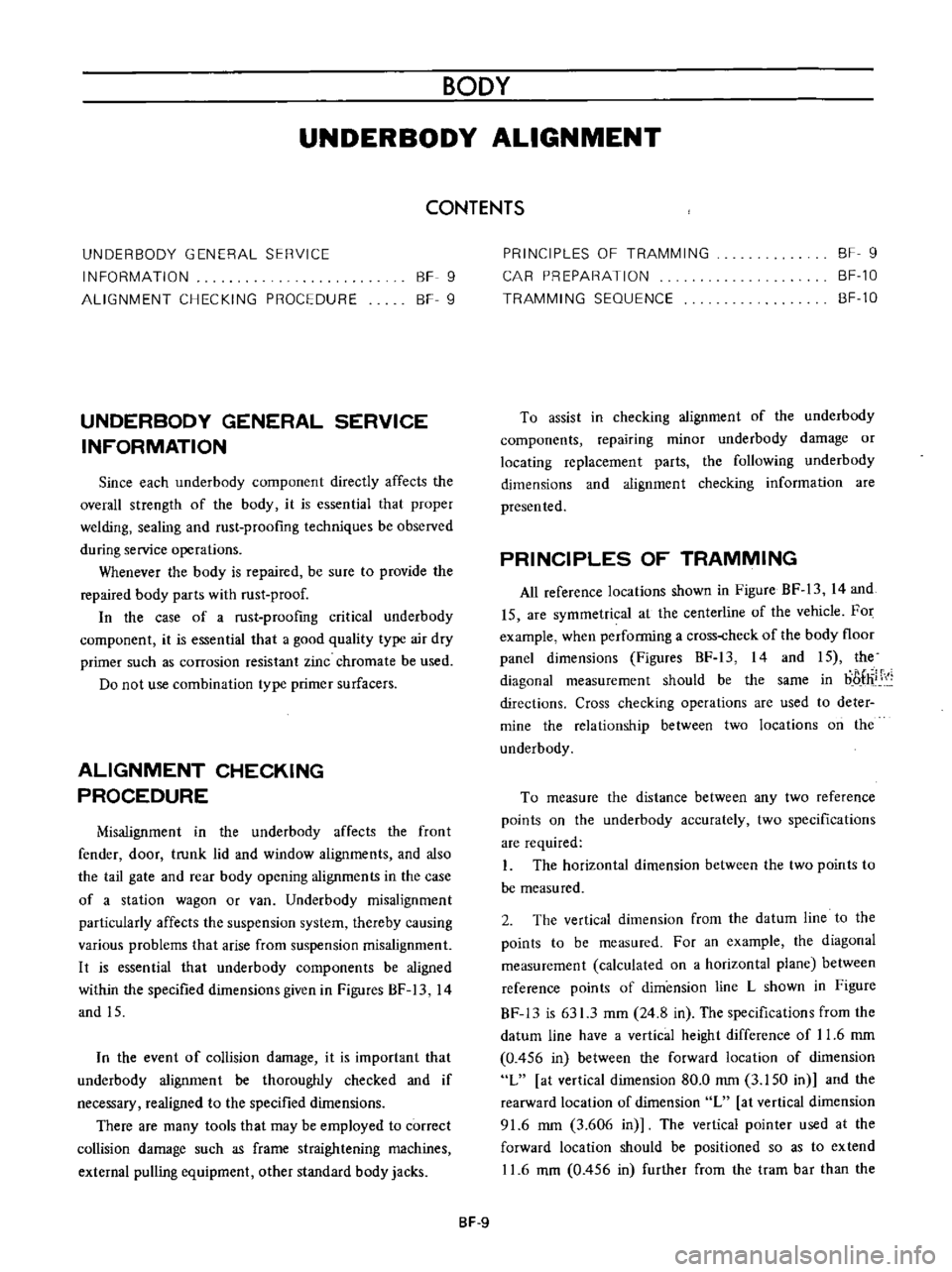
All
reference
locations
shown
in
Figure
BF
13
14
and
15
are
symmetrical
at
the
centerline
of
the
vehicle
For
example
wheo
performing
a
crosHheck
of
the
body
floor
panel
dimensions
Figures
BF
I3
14
and
IS
the
diagonal
measurement
should
be
the
same
in
boflii
directions
Cross
checking
operations
are
used
to
deter
mine
the
relationship
between
two
locations
on
the
underbody
To
measure
the
distance
between
any
two
reference
points
on
the
underbody
accurately
two
specifications
are
required
I
The
horizontal
dimension
between
the
two
points
to
be
measured
2
The
vertical
dimension
from
the
datum
line
to
the
points
to
be
measured
For
an
example
the
diagonal
measurement
calculated
on
a
horizontal
plane
between
reference
points
of
dimension
line
L
shown
in
Figure
BF
I3
is
631
3
mm
24
8
in
The
specifications
from
the
datum
line
have
a
vertical
height
difference
of
11
6
mm
0
456
in
between
the
forward
location
of
dimension
L
at
vertical
dimension
80
0
mm
3
150
in
and
the
rearward
location
of
dimension
L
at
vertical
dimension
91
6
mm
3
606
in
The
vertical
pointer
used
at
the
forward
location
should
be
positioned
so
as
to
extend
11
6
mm
0
456
in
further
from
the
tram
bar
than
the
BF
9
Page 200 of 513
pointer
used
at
the
rearward
lut
atiol1
With
the
proper
scttings
the
tram
bar
will
be
on
a
piane
parallel
to
that
of
the
body
The
exception
to
this
would
be
wht
n
one
of
the
reterence
locations
is
induded
in
the
misaligned
area
then
the
parallel
plane
between
the
body
and
the
tram
bar
may
not
prevail
After
completiun
of
the
repairs
the
tram
gauge
should
be
set
at
the
specitled
dimension
to
check
the
accuracy
of
the
repair
operation
CAR
PREPARATION
Preparing
the
car
for
the
underbody
alignment
check
involves
the
following
Place
the
car
on
a
level
surface
2
The
weight
of
the
car
should
be
supported
at
the
wheel
locations
3
A
visual
damage
inspection
should
be
made
to
eliminate
unnecessary
measuring
Obviously
damaged
or
misaligned
areas
may
often
be
located
visually
BODY
TRAMMING
SEQUENCE
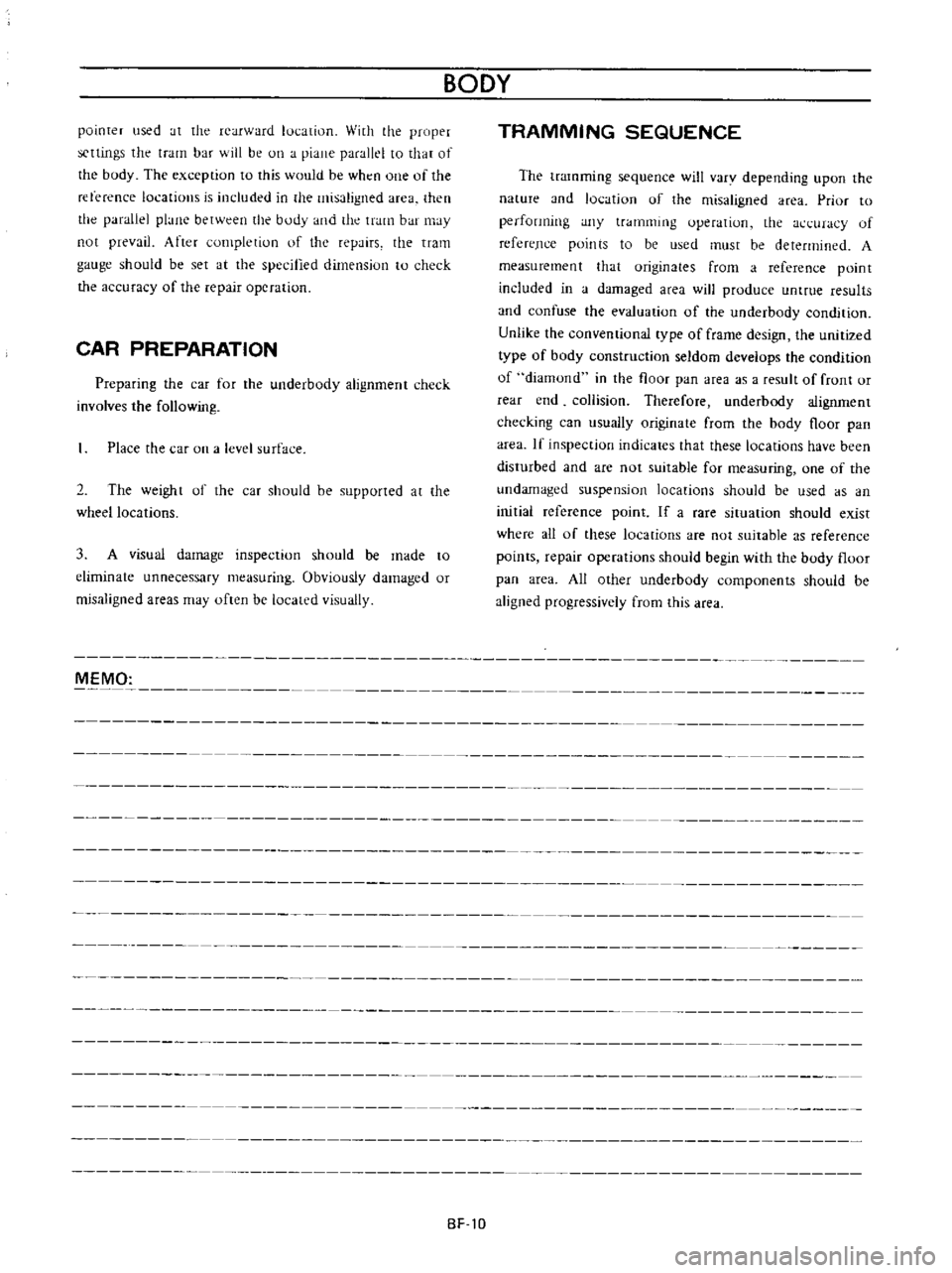
The
tramming
sequence
will
varv
depending
upon
the
nature
and
IOl
atiun
uf
the
misaligned
area
Priur
to
performing
any
tramming
uperation
the
h
uracy
of
refereJlce
points
to
be
used
must
be
determined
A
measurement
that
originates
from
a
reference
point
included
in
a
damaged
area
will
produce
untrue
results
and
confuse
the
evaluation
of
the
underbody
condition
Unlike
the
conventional
type
of
frame
design
the
unitized
type
of
body
construction
seldom
develops
the
condition
of
diamond
in
the
floor
pan
area
as
a
result
of
front
or
rear
end
collision
Therefore
underbody
alignment
checking
can
usually
originate
from
the
body
floor
pan
area
If
inspection
indicates
that
these
locations
have
been
disturbed
and
are
not
suitable
for
measuring
one
of
the
undamaged
suspension
locations
should
be
used
as
an
initial
reference
point
If
a
rare
situation
should
exist
where
all
of
these
lucalions
are
not
suitable
as
reference
points
repair
operations
should
begin
with
the
body
floor
pan
area
All
other
underbody
components
should
be
aligned
progressively
from
this
area
MEMO
BF
10