1973 DATSUN B110 height
[x] Cancel search: heightPage 32 of 513
CHASSIS
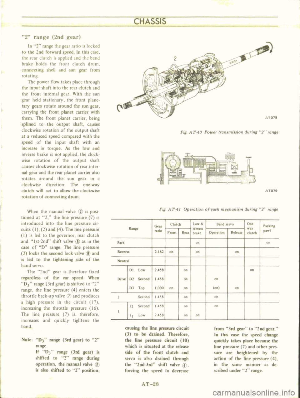
2
range
2nd
gear
In
2
range
the
gear
ratio
is
locked
to
the
2nd
forward
speed
In
this
case
the
rear
clutch
is
applied
and
the
band
brake
holds
the
front
clutch
drum
connecting
shell
and
sun
gear
from
rotating
The
power
flow
takes
place
through
the
input
shaft
into
the
rear
clutch
and
the
front
internal
gear
With
the
sun
gear
held
stationary
the
front
plane
lacy
gears
rotate
around
the
sun
gear
carrying
the
front
planet
carrier
with
them
The
front
planet
carrier
being
splined
to
the
output
shaft
causes
clockwise
rotation
of
the
output
shaft
at
a
reduced
speed
compared
with
the
speed
of
the
input
shaft
with
an
increase
in
torque
As
the
low
and
reverse
brake
is
not
applied
the
clock
wise
mlation
of
the
output
shaft
causes
clockwise
rotation
of
rear
inter
nal
gear
and
the
rear
planet
carrier
also
rotates
around
the
sun
gear
in
a
clockwise
direction
The
one
way
c1urch
will
act
to
allow
the
clockwise
rotation
of
connecting
drum
When
the
manual
valve
CV
is
posi
tioned
at
2
the
line
pressure
7
is
introduced
into
the
line
pressure
cir
cuits
I
2
and
4
The
line
pressure
I
is
led
to
the
governur
rear
dutch
and
Ist
2nd
shift
valve
ID
as
in
the
case
of
D
range
The
line
pressure
2
locks
the
second
lock
valve
@
and
is
led
to
the
tightening
side
of
the
band
servo
The
2nd
gear
is
therefore
fixed
regardless
of
the
car
speed
When
DJ
range
3rd
gear
is
shifted
to
2
range
the
line
pressure
4
enters
the
throttle
back
up
valve
IJ
and
produces
a
high
pressure
in
the
circuit
17
increasing
the
throttle
pressure
16
The
line
pressure
7
is
therefore
increases
and
quickly
tightens
the
band
Note
DJ
range
3rd
gear
to
2
range
If
DJ
range
3rd
gear
is
shifted
to
2
range
during
operation
the
manual
valve
CV
is
also
shifted
to
2
position
Fig
A
T
40
Powu
transmission
during
2
range
f
IY
9
3
AT079
Fig
A
T
41
Operation
of
each
mechanism
during
2
range
Gear
Clutch
low
Band
servo
On
Parking
Range
ratio
w
pawl
Front
Rear
brake
Operation
Relea
se
clutch
Park
on
on
Reverse
2
182
on
on
on
Neutral
I
t
Low
2
4S8
on
on
Drive
1
2
Second
1
458
on
on
1
Top
t
OOO
on
on
on
on
2
Second
1
458
on
on
12
Second
1
458
on
on
t
tt
Low
2
458
on
on
causing
the
line
pressure
circuit
3
to
be
drained
Therefore
the
line
pressure
circuit
10
which
is
situated
at
the
release
side
of
the
front
clutch
and
senro
is
also
drained
through
the
2nd
3rd
shift
valve
@
forcing
the
speed
to
decrease
from
3rd
gear
to
2nd
gear
In
this
case
the
speed
change
quickly
takes
place
because
the
line
pressure
7
and
other
pres
sure
are
heightened
by
the
action
of
the
line
pressure
4
in
the
same
manner
as
de
scribed
under
2
range
AT
28
Page 54 of 513

through
all
drive
positions
and
place
the
lever
in
park
P
position
In
this
inspection
the
car
must
be
placed
on
a
level
surface
The
amount
of
the
oil
varies
with
the
temperature
As
a
rule
the
oil
level
must
be
measured
after
its
tempera
ture
becomes
sufficiently
high
I
Fill
the
oil
to
the
line
H
The
difference
of
capacities
between
both
H
and
L
is
approximately
0
4
liter
7
8
U
S
pt
3
4
Imper
pt
and
therefore
take
care
not
to
fill
beyond
the
line
H
2
At
the
time
of
the
above
topping
up
and
changing
of
oil
care
should
be
taken
of
to
prevent
mixing
the
oil
with
dust
and
water
2
Inspecting
oil
condition
The
condition
of
oil
sticking
to
the
level
gauge
indicates
whether
to
over
haul
and
repair
the
transmission
or
look
for
the
defective
part
If
the
oil
has
deteriorated
into
a
varnish
like
quality
it
causes
the
con
trol
valve
to
stick
The
blackened
oil
gives
the
proof
of
the
burned
clutch
brake
band
etc
In
these
cases
the
transmission
must
be
replaced
Notes
a
In
oil
level
checking
use
special
paper
waste
to
handle
the
level
gauge
and
take
care
not
to
let
the
scraps
of
paper
and
cloth
tick
to
the
gauge
b
Insert
the
gauge
fully
and
take
it
out
quickly
before
splashing
oil
adheres
to
the
gauge
and
theu
observe
the
level
c
Use
automatic
transmission
fluid
having
DEXRON
iden
tIficatIon
only
in
the
3N71
B
automatic
transmission
d
Pay
atteutIon
because
the
oil
to
be
used
dIffers
from
that
i
used
in
the
Nissan
Full
Automatic
Transmission
3N7IA
Never
mix
the
oil
with
that
CHASSIS
Inspection
and
repair
of
oil
leakage
When
oil
leakage
takes
place
the
portion
near
the
leakage
is
covered
with
oil
presenting
difficulty
in
de
tecting
the
spot
Therefore
the
places
where
oil
seals
and
gaskets
are
equipped
are
enumerated
below
I
Converter
housing
The
rubber
ring
of
oil
pump
hous
ing
The
oil
eaI
of
oil
pump
housing
The
oil
seal
of
engine
crankshaft
The
bolts
of
converter
housing
to
case
2
Transmission
and
rear
extension
Junction
of
transmission
and
rear
extension
Oil
tube
connectors
Oil
pan
Oil
pressure
inspection
holes
Refer
to
Figure
AT
112
The
mounting
portion
of
vacuum
diaphragm
and
downshift
solenoid
Breather
and
oil
charging
pipe
Speedometer
pinion
sleeve
The
oil
seal
of
rear
extension
To
exactly
locate
the
place
of
oil
leakage
proceeds
as
follows
Place
the
vehicle
in
a
pit
and
by
sampling
the
leaked
oil
examine
whe
ther
it
is
the
torq
le
converter
oil
or
not
The
torque
converter
oil
assumes
color
like
red
wine
when
shipped
from
the
factory
so
it
is
ea
ily
distin
guished
from
engine
oil
or
gear
oil
Cleanly
wipe
off
the
leaking
oil
and
dust
and
detect
the
spot
of
oil
leakage
Use
nonflammable
organic
solvent
such
as
carbon
tetrachloride
for
wip
ing
Raise
the
oil
temperature
by
op
erating
the
engine
and
shift
the
lever
to
0
to
heighten
the
oil
pressure
The
spot
of
oil
leakage
will
then
be
found
more
easily
Note
A
the
oil
leakage
from
the
breather
does
not
take
place
except
when
running
at
high
speed
it
is
impossible
to
locate
the
spot
of
leakage
with
vehicle
stalled
AT
50
Checking
engine
idling
rprn
The
engine
idling
revolution
should
be
properly
adjusted
If
the
engine
revolution
is
too
low
the
engine
does
not
operate
smoothly
and
if
too
high
a
strong
shock
or
creep
develops
when
changing
over
from
N
to
D
or
R
Specified
idling
speed
650
rpm
at
D
position
800
rpm
at
N
position
Checking
and
adjusting
kick
down
switch
and
downshift
solenoid
When
the
kick
down
operation
is
not
made
properly
or
the
speed
chang
ing
point
is
too
high
check
the
kick
down
switch
downshift
solenoid
and
wiring
between
them
When
the
igni
tion
key
is
positioned
at
the
1st
stage
and
the
accelerator
pedal
is
depressed
deeply
the
switch
contact
should
be
closed
and
the
solenoid
should
click
If
it
does
not
click
it
indicates
a
defect
Then
check
each
part
with
the
testing
instruments
See
Figure
AT
I09
0
0
1
M
r
7
I
Y
ATl08
Fig
A
T
l
09
Downshift
solenoid
Note
Watch
for
oil
leakage
from
transmission
case
Page 72 of 513

PROPELLER
SHAFT
DIFFERENTIAL
CARRIER
The
gear
carrier
is
made
of
light
and
strong
aluminum
alloy
metal
and
hypoid
bevel
gear
is
used
Adjust
drive
pinion
bearing
preload
with
non
adjusting
type
spacer
and
pinion
height
and
side
bearing
adjust
ment
with
spacer
shim
s
Millimeter
standardization
stilI
remains
for
all
the
screw
threads
of
this
unit
Therefore
adjustment
figures
stamped
on
screws
adjusting
shims
washers
differential
case
drive
pinion
and
carrier
are
in
millimeters
in
accordance
with
the
millimeter
standardization
of
parts
The
proper
lubrication
to
the
gear
housing
is
necessary
otherwise
it
would
shorten
the
durability
of
the
gear
and
cause
other
troubles
The
lubricant
should
be
checked
each
5
000
km
3
000
miles
and
replenished
each
50
000
km
30
000
miles
The
lubricant
should
be
drained
and
ref11led
at
the
end
of
the
first
1
000
km
600
miles
to
eliminate
any
loose
material
from
the
sump
which
results
from
breaking
Differential
lubricant
should
be
changed
at
least
every
50
000
km
30
000
miles
ConsIderations
should
be
given
to
the
following
matters
I
Nominated
hypoid
gear
oil
must
be
used
2
It
is
prohibited
to
use
any
gear
oil
of
different
viscosity
The
same
brand
must
always
be
selected
3
The
standard
oil
capacity
is
about
0
75
liter
0
198
US
gal
REMOVAL
Fig
PD
5
Removing
differential
gear
carrier
To
remove
the
gear
carrier
assembly
disconnect
the
drive
pinion
companion
flange
te
flange
yoke
connection
and
remove
two
rear
axle
shafts
Refer
to
REAR
AXLE
for
the
work
DISASSEMBLY
I
Install
the
gear
carrier
assembly
on
the
Gear
Carrier
Attachment
ST06320000
ST06320000
Fig
PD
6
Holding
differential
camer
2
Inspect
the
following
before
disassembling
I
Inspect
the
tooth
contact
pattern
with
a
lead
oxide
2
Measure
backlash
between
drive
gear
and
pinion
gear
using
a
dial
indicator
3
Put
match
mark
on
one
side
of
the
side
bearing
cap
by
the
use
of
a
punch
SIDCBEMING
c
e
Fig
PD
7
Putting
mark
PD
5
Page 77 of 513
CHASSIS
Setting
and
adjusting
drive
pinion
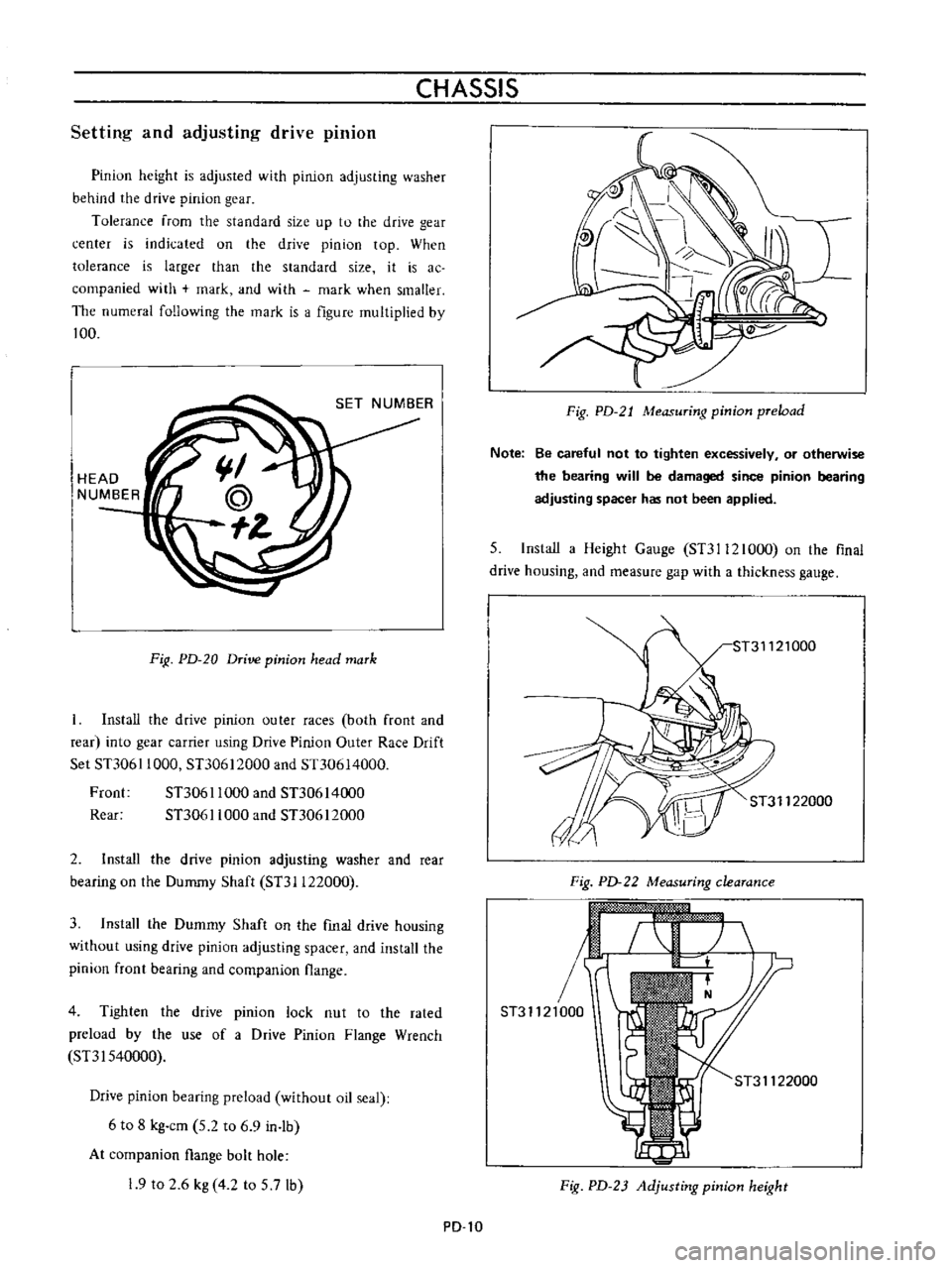
Pinion
height
is
adjusted
with
pinion
adjusting
washer
behind
the
drive
pinion
gear
Tolerance
from
the
standard
size
up
to
the
drive
gear
center
is
indicated
on
the
drive
pinion
top
When
tolerance
is
larger
than
the
standard
size
it
is
ac
companied
with
mark
and
with
mark
when
smaller
The
numeral
following
the
mark
is
a
figure
multiplied
by
100
HEAD
NUMBER
FiR
PD
20
Drive
pinion
head
mark
Install
the
drive
pinion
outer
races
both
front
and
rear
into
gear
carrier
using
Drive
Pinion
Outer
Race
Drift
Set
STJ061
1000
STJ0612000
and
Sn0614000
Froot
STJ061
1000
and
STJ0614000
Rear
STJ061
1000
and
STJ0612000
2
Install
the
drive
pinion
adjusting
washer
and
rear
bearing
on
the
Dummy
Shaft
STJI122000
3
Install
the
Dummy
Shaft
on
the
fmal
drive
housing
without
using
drive
pinion
adjusting
spacer
and
install
the
pinion
front
bearing
and
companion
flange
4
Tighten
the
drive
pinion
lock
nut
to
the
rated
preload
by
the
use
of
a
Drive
Pinion
Flange
Wrench
SnI540000
Drive
pinion
bearing
preload
without
oil
seal
6
to
8
kg
cm
5
2
to
6
9
in
lb
At
companion
flange
bolt
hole
19
to
2
6
kg
4
2
to
5
7lb
PD
l0
Fig
PD
21
Measuring
pinion
preload
Note
Be
careful
not
to
tighten
excessively
or
otherwise
the
bearing
will
be
damaged
since
pinion
bearing
adjusting
spacer
has
not
been
applied
5
Install
a
Height
Gauge
STJI12l000
on
the
flnal
drive
housing
and
measure
gap
with
a
thickness
gauge
ST31122000
Fig
PD
22
Measuring
clearance
r
ST31121000
ST31122000
Fig
PD
23
Adjusting
pinion
height
Page 78 of 513
PROPELLER
SHAFT
DIFFERENTIAL
CARRIER
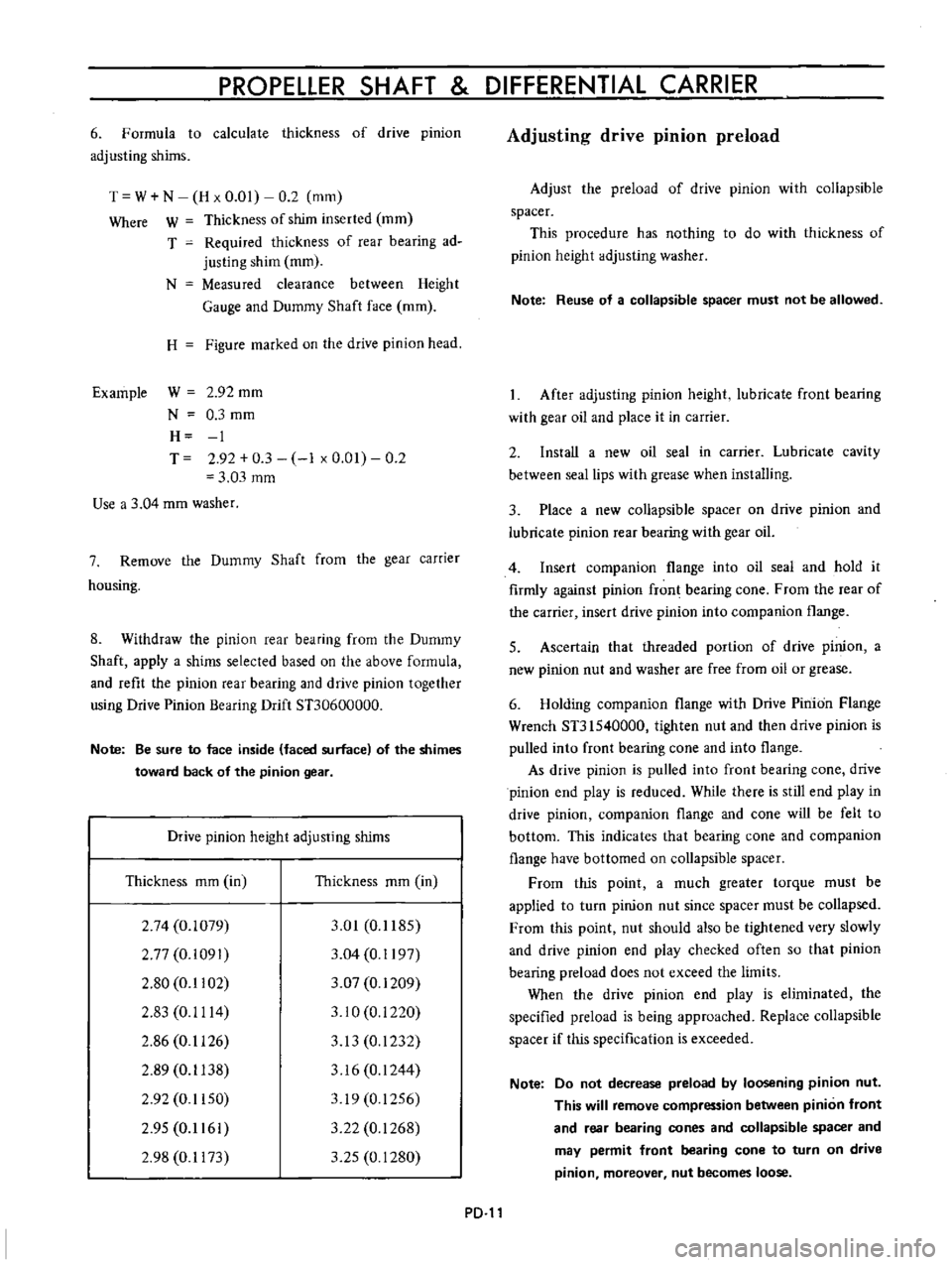
6
Formula
to
calculate
thickness
of
drive
pinion
adjusting
shims
T
W
N
H
x
0
01
0
2
mm
Where
W
Thickness
of
shim
inserted
mm
T
Required
thickness
of
rear
bearing
ad
justing
shim
mm
N
Measured
clearance
between
Height
Gauge
and
Dummy
Shaft
face
mm
H
Figure
marked
on
the
drive
pinion
head
Example
W
2
92
mm
N
0
3
mm
H
1
T
2
92
0
3
1
x
0
01
0
2
3
03
mm
Use
a
3
04
mm
washer
7
Remove
the
Dummy
Shaft
from
the
gear
carrier
housing
8
Withdraw
the
pinion
rear
bearing
from
the
Dummy
Shaft
apply
a
shims
selected
based
on
the
above
formula
and
refit
the
pinion
rear
bearing
and
drive
pinion
together
using
Drive
Pinion
Bearing
Drift
STJ0600000
Note
Be
sure
to
face
inside
faced
surface
of
the
shimes
toward
back
of
the
pinion
gear
Drive
pinion
height
adjusting
shims
Thickness
mm
in
Thickness
mm
in
2
74
0
1079
2
77
0
i091
2
80
0
1102
2
83
0
1114
2
86
0
1126
2
89
0
1138
2
92
0
1150
2
95
0
1161
2
98
0
1173
3
01
0
1185
3
04
0
1197
3
07
0
1209
3
10
0
i
220
3
13
0
1232
3
16
0
1244
319
0
1256
3
22
0
1268
3
25
0
1280
PD
Adjusting
drive
pinion
preload
Adjust
the
preload
of
drive
pinion
with
collapsible
spacer
This
procedure
has
nothing
to
do
with
thickness
of
pinion
height
adjusting
washer
Note
Reuse
of
a
collapsible
spacer
must
not
be
allowed
After
adjusting
pinion
height
lubricate
front
bearing
with
gear
oil
and
place
it
in
carrier
2
Install
a
new
oil
seal
in
carrier
Lubricate
cavity
between
seal
lips
with
grease
when
installing
3
Place
a
new
collapsible
spacer
on
drive
pinion
and
lubricate
pinion
rear
bearing
with
gear
oil
4
Insert
companion
flange
into
oil
seal
and
hold
it
firmly
against
pinion
fron
bearing
cone
From
the
rear
of
the
carrier
insert
drive
pinion
into
companion
flange
5
Ascertain
that
threaded
portion
of
drive
pinion
a
new
pinion
nut
and
washer
are
free
from
oil
or
grease
6
Holding
companion
flange
with
Drive
Pinion
Flange
Wrench
ST31540000
tighten
nut
and
then
drive
pinion
is
pulled
into
front
bearing
cone
and
into
flange
As
drive
pinion
is
pulled
into
front
bearing
cone
drive
pinion
end
play
is
reduced
While
there
is
still
end
play
in
drive
pinion
companion
flange
and
cone
will
be
felt
to
bottom
This
indicates
that
bearing
cone
and
companion
flange
have
bottomed
on
collapsible
spacer
From
this
point
a
much
greater
torque
must
be
applied
to
turn
pinion
nut
since
spacer
must
be
collapsed
From
this
point
nut
should
also
be
tightened
very
slowly
and
drive
pinion
end
play
checked
often
so
that
pinion
bearing
preload
does
not
exceed
the
limits
When
the
drive
pinion
end
play
is
eliminated
the
specified
preload
is
being
approached
Replace
collapsible
spacer
if
this
specification
is
exceeded
Note
Do
not
decrease
preload
by
loosening
pinion
nut
This
will
remove
compression
between
pinion
front
and
rear
bearing
cones
and
collapsible
spacer
and
may
permit
front
bearing
cone
to
turn
on
drive
pinion
moreover
nut
becomes
loose
Page 100 of 513
CHASSIS
Fig
FA
35
Removing
O
ring
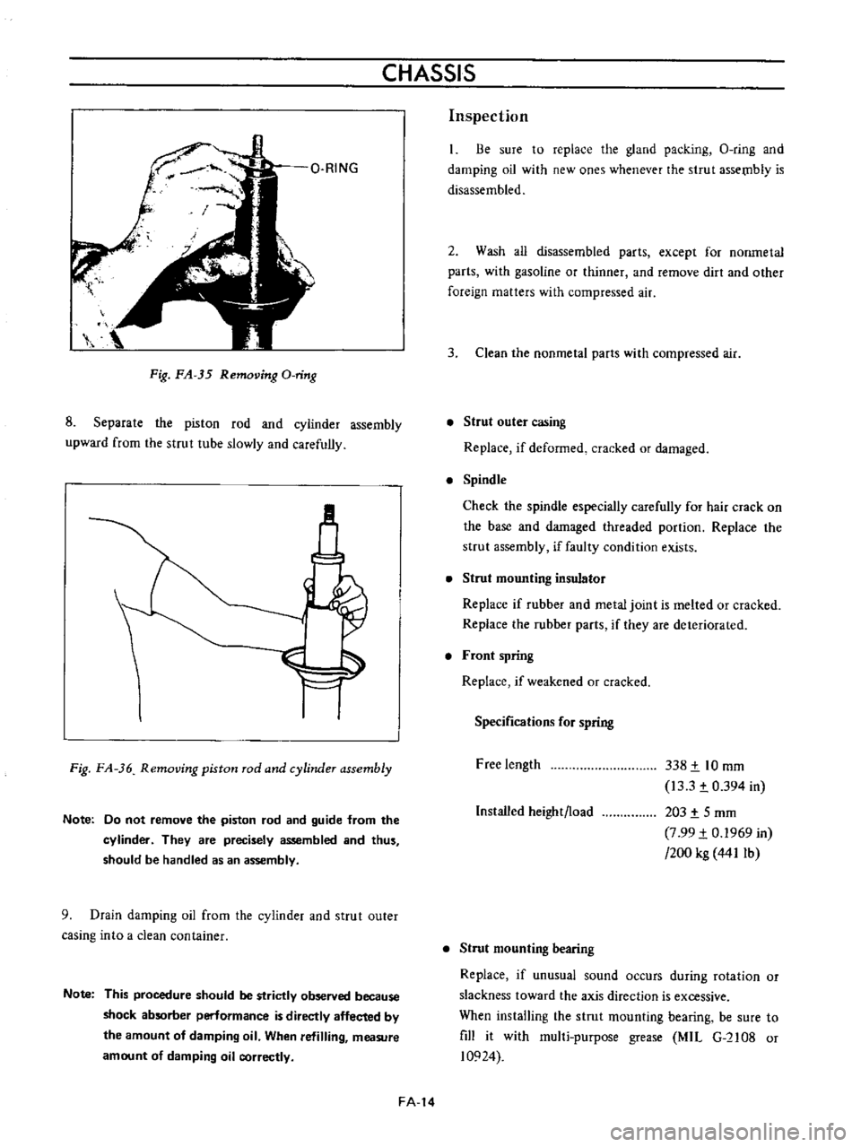
8
Separate
the
piston
rod
and
cyiinder
assembly
upward
from
the
strut
tube
slowly
and
carefully
M
Fig
FA
36
Removing
piston
rod
and
cylinder
assembly
Note
Do
not
remove
the
piston
rod
and
guide
from
the
cylinder
They
are
precisely
assembled
and
thus
should
be
handled
as
an
assembly
9
Drain
damping
oil
from
the
cylinder
and
strut
outer
casing
into
a
clean
container
Note
This
procedure
should
be
strictly
observed
because
shock
absorber
perlormance
is
directly
affected
by
the
amount
of
damping
oil
When
refilling
measure
amount
of
damping
oil
correctly
FA
14
Inspection
Be
sure
to
replace
the
gland
packing
O
ring
and
damping
oil
with
new
ones
whenever
the
strut
assetnb1y
is
disassembled
2
Wash
all
disassembled
parts
except
for
nonmetal
parts
with
gasoline
or
thinner
and
remove
dirt
and
other
foreign
matters
with
compressed
air
3
Clean
the
nonmetal
parts
with
compressed
air
Strut
outer
casing
Replace
if
deformed
cracked
or
damaged
Spindle
Check
the
spindle
especially
carefully
for
hair
crack
on
the
base
and
damaged
threaded
portion
Replace
the
strut
assembly
if
faulty
condition
exists
Strut
mounting
insulator
Replace
if
rubber
and
metal
joint
is
melted
or
cracked
Replace
the
rubber
parts
if
they
are
deteriorated
Front
spring
Replace
if
weakened
or
cracked
Specifications
for
spring
Free
length
338
t
10
mm
13
3
t
0
394
in
203
t
5
mm
7
99
t
0
1969
in
200
kg
441Ib
Installed
height
load
Strut
mounting
bearing
Replace
if
unusual
sound
occurs
during
rotation
or
slackness
toward
the
axis
direction
is
excessive
When
installing
the
strut
mounting
bearing
be
sure
to
fill
it
with
mul1i
purpose
grease
MIL
G
2108
or
10924
Page 108 of 513
CHASSIS
For
high
speed
Over
100
km
h
or
60
MPH
ADJUSTMENT
OF
WHEEL
ALIGNMENT
Use
a
turning
radius
gauge
and
alignment
gauge
for
the
measurement
2
Carry
out
wheel
alignment
on
a
flat
surface
with
tire
air
pressure
adjusted
to
the
normal
pressure
ADJUSTMENT
OF
VEHICLE
LEVEL
Vehicle
level
is
adjusted
by
changing
springs
ADJUSTMENT
OF
TOE
IN
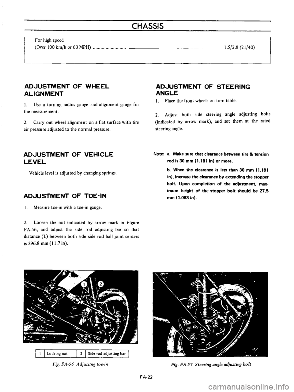
Measure
toe
in
with
a
toe
in
gauge
2
Loosen
the
nut
indicated
by
arrow
mark
in
Figure
FA
56
and
adjust
the
side
rod
adjusting
bar
so
that
distance
L
between
both
side
side
rod
ball
joint
centers
is
296
8
mm
11
7
in
I
1
I
Locking
nu
t
I
2
I
Side
rod
adjusting
bar
I
Fig
FA
56
Adjusitng
toe
in
1
5
2
8
21
40
ADJUSTMENT
OF
STEERING
ANGLE
1
Place
the
front
wheels
on
turn
table
2
Adjust
both
side
steering
angle
adjusting
bolts
indicated
by
arrow
mark
and
set
them
al
the
rated
steering
angle
Note
8
Make
sure
that
clearance
between
tire
tension
rod
is
30
mm
11
181
in
or
more
b
When
the
clearance
is
less
than
30
mm
1
181
in
inaease
the
clearance
by
extending
the
stopper
bolt
Upon
completion
of
the
adjustment
max
imum
height
of
the
stopper
bolt
should
be
27
5
mm
1
083
in
Fig
FA
57
Steering
angle
adjusting
bolt
FA
22
Page 109 of 513
FRONT
AXLE
FRONT
SUSPENSION
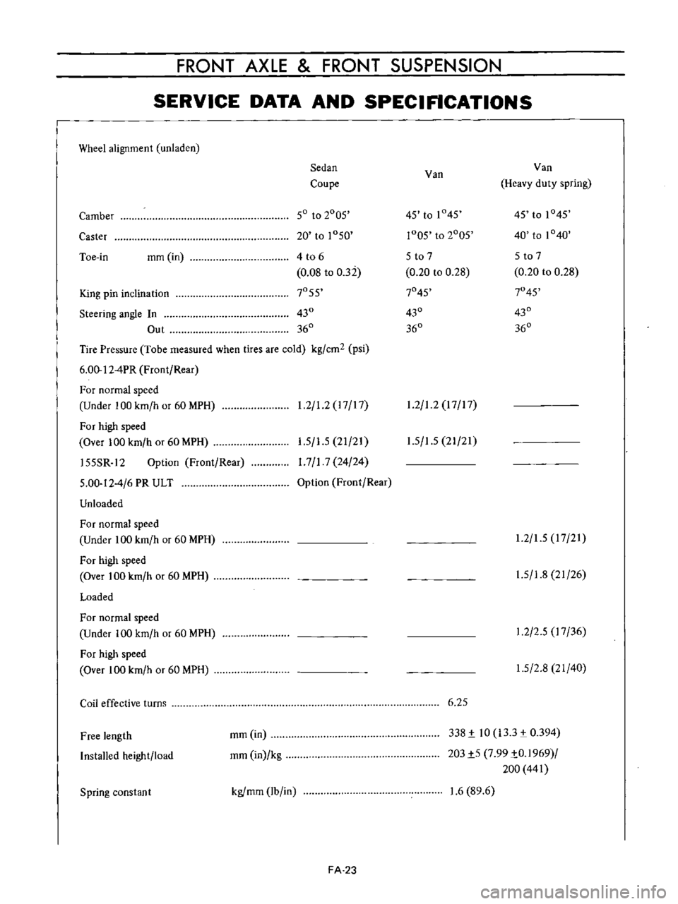
SERVICE
DATA
AND
SPECIFICATIONS
Wheel
alignment
unladen
Sedan
Van
Van
Coupe
Heavy
duty
spring
Camber
50
to
2005
45
to
1
45
45
to
1045
Caster
20
to
1050
r005
to
2005
40
to
1040
Toe
in
mm
in
4
t06
5
to
7
5
to
7
0
08
to
032
0
20
to
0
28
0
20
to
0
28
King
pin
inclination
7055
7045
7045
Steering
angle
In
430
430
430
Out
360
360
360
Tire
Pressure
Tobe
measured
when
tires
are
cold
kg
cm2
psi
6
00
12
4PR
Front
Rear
For
normal
speed
Under
100
km
h
or
60
MPH
1
2
1
2
17
17
1
2
1
2
17
17
For
high
speed
Over
100
km
h
or
60
MPH
155SR
12
Option
Front
Rear
5
00
12
4
6
PR
ULT
Unloaded
1
5
1
5
21
21
1
7
1
7
24
24
Option
Front
Rear
1
5
1
5
21
21
For
normal
speed
Under
100
km
h
or
60
MPH
For
high
speed
Over
100
km
h
or
60
MPH
Loaded
1
2
1
5
17
21
1
5
1
8
21
26
For
normal
speed
Under
100
km
h
or
60
MPH
For
high
speed
Over
100
km
h
or
60
MPH
1
2
2
5
17
36
1
5
2
8
21
40
Coil
effective
turns
6
25
Free
length
Installed
height
load
mm
in
mm
in
kg
338
i
10
133
0394
203i5
7
99
iO
1969
200
441
Spring
constan
t
kgfmm
lb
in
1
6
89
6
FA
23