1973 DATSUN B110 height
[x] Cancel search: heightPage 112 of 513
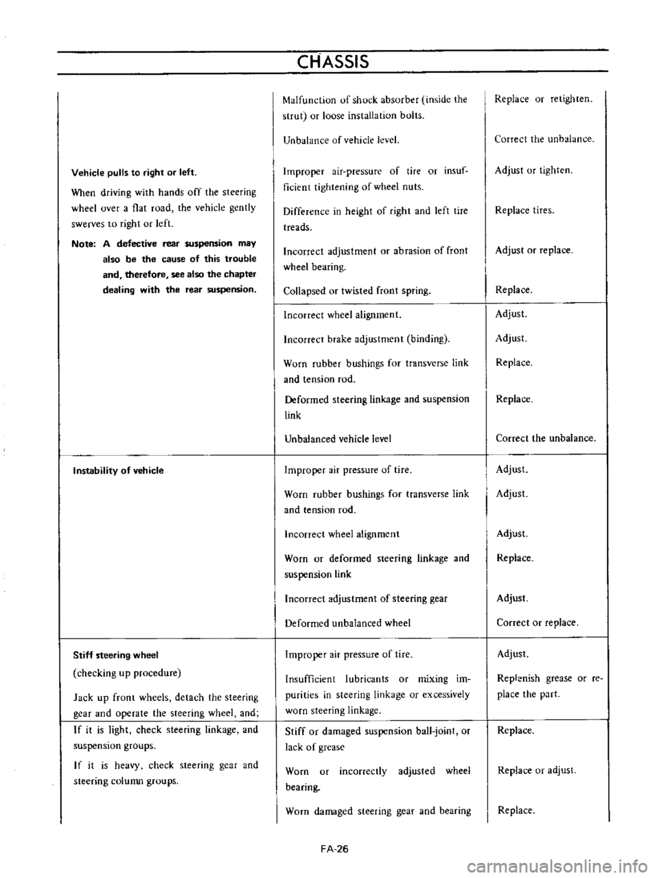
Vehicle
pulls
to
right
or
left
When
driving
with
hands
off
the
steering
wheel
over
a
flat
road
the
vehicle
gently
swerves
to
right
or
left
Note
A
defective
rear
suspension
may
also
be
the
cause
of
this
trouble
and
therefore
see
also
the
chapter
dealing
with
the
rear
suspension
Instability
of
vehicle
Stiff
steering
wheel
checking
up
procedure
Jack
up
front
wheels
detach
the
steering
gear
and
operate
the
steering
wheel
and
If
it
is
light
check
steering
linkage
and
suspension
groups
If
it
is
heavy
check
steering
gear
and
steering
colunm
groups
CHASSIS
Malfunction
of
shock
absorber
inside
the
strut
or
loose
installation
bolts
Unbalance
of
vehicle
level
Improper
air
pressure
of
tire
or
insuf
ficient
tightening
of
wheel
nuts
Difference
in
height
of
right
and
left
tire
treads
Incorrect
adjustment
or
abrasion
of
front
wheel
bearing
Collapsed
or
twisted
front
spring
Incorrect
wheel
alignment
Incorrect
brake
adjustment
binding
Worn
rubber
bushings
for
transverse
link
and
tension
rod
Deformed
steering
linkage
and
suspension
link
Unbalanced
vehicle
level
Improper
air
pressure
of
tire
Worn
rubber
bushings
for
transverse
link
and
tension
rod
Incorrect
wheel
alignment
Worn
or
deformed
steering
linkage
and
suspension
link
Incorrect
adjustment
of
steering
gear
Deformed
unbalanced
wheel
Improper
air
pressure
of
tire
Insufficient
lubricants
or
mixing
im
purities
in
steering
linkage
or
excessively
worn
steering
linkage
Stiff
or
damaged
suspension
ball
joint
or
lack
of
grease
Worn
or
incorrectly
adjusted
wheel
bearing
Worn
damaged
steering
gear
and
bearing
FA
26
Replace
or
retighten
Correct
the
unbalance
Adjust
or
tighten
Replace
tires
Adjust
or
replace
Replace
Adjust
Adjust
Replace
Replace
Correct
the
unbalance
Adjust
Adjust
Adjust
Replace
Adjust
Correct
or
replace
Adjust
Repl
nish
grease
or
re
place
the
part
Replace
Replace
or
adjust
Replace
Page 125 of 513
DESCRIPTION
BRAKE
PEDAL
Removal
Inspection
Reinstallation
TANDEM
MASTER
CYLINDER
Removal
Disassembly
Inspection
Reassembly
Reinstallation
SINGLE
MASTER
CYLINDER
Removal
and
disassembly
Inspection
Reassembly
and
reinstallation
BRAKE
LINE
Removal
Inspection
Reinstallation
Brake
line
pressure
differential
warning
light
switch
FRONT
DRUM
BRAKE
cr
I
1
0
I
I
CD
BRAKE
BRAKE
CONTENTS
BR
2
BR
2
BR
2
BR
2
BR
2
BR
3
BR
3
BR
3
BR
3
BR
4
BR
4
BR
4
BR
5
BR
5
BR
5
BR
5
BR
5
BR
6
BR
6
BR
7
BR
8
Removal
and
disassembly
Inspection
Reassembly
and
reinstallation
FRONT
DISC
BRAKE
Brake
pad
Caliper
assembly
Reassembly
Reinstallation
REAR
BRAKE
Removal
and
disassembly
Inspection
Reassembly
and
reinstallation
HAND
8RAKE
Removal
Inspection
Reinstallation
ADJUSTMENT
Brake
shoe
clearance
Brake
pedal
height
Hand
brake
Bleeding
hydraulic
system
@
7
o
i
1
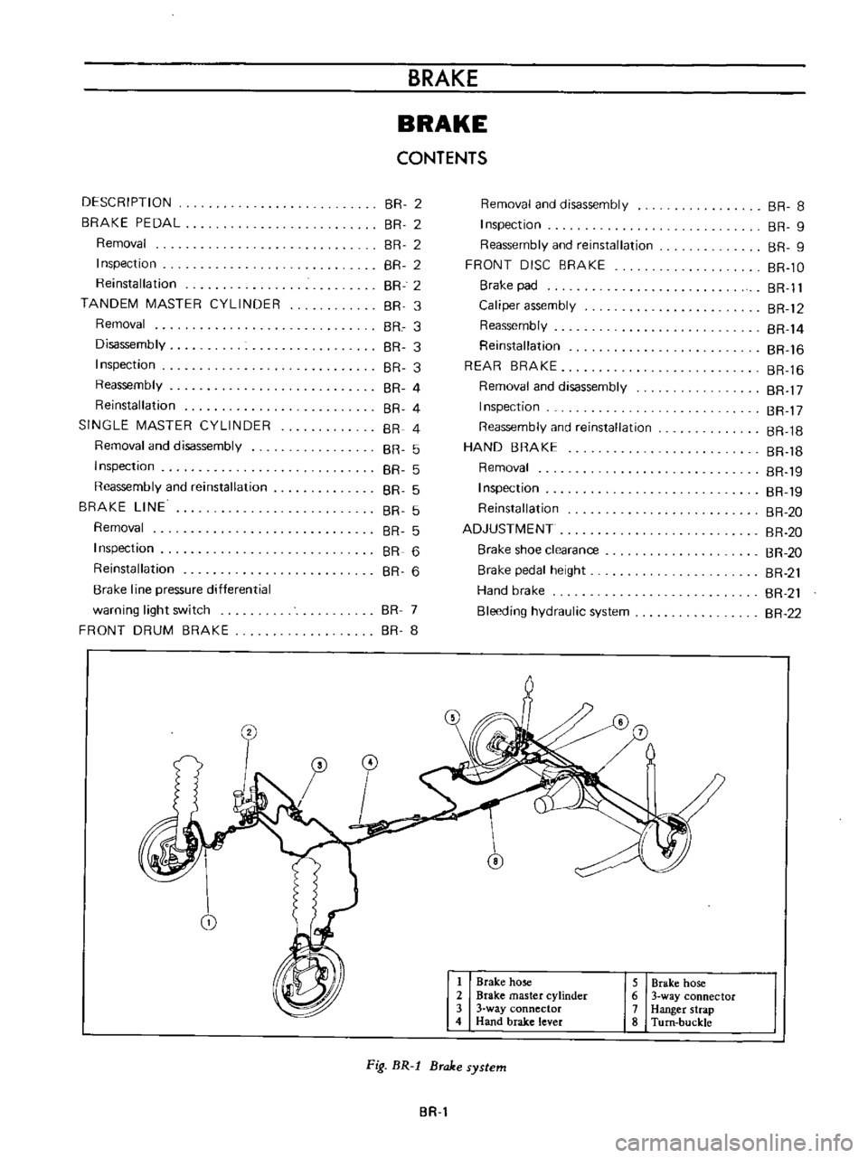
Brake
hose
2
Brake
master
cylinder
3
3
way
connector
4
Hand
brake
lever
5
Brake
hose
6
3
way
connector
7
Hanger
strap
8
Turn
buckle
Fig
BR
l
Brake
system
BR
BR
8
BR
9
BR
9
BR
lO
BR
Il
BR
12
BR
14
BR
16
BR
16
BR
17
BR
17
BR
18
BR
18
BR
19
BR
19
BR
20
BR
20
BR
20
BR
21
BR
21
BR
22
Page 128 of 513
CHASSIS
Ii
t
L
1
J
rJ
I
e
i
L
rubber
parts
und
alcohol
long
than
30
seconds
After
the
parts
are
cleaned
dry
them
with
com
pressed
air
Check
the
cylinder
and
piston
for
damage
and
uneven
wear
on
the
sliding
surface
and
for
other
defective
conditions
Replace
as
required
2
Replace
if
the
cylinder
and
piston
clearance
is
more
than
0
15
mm
0
006
in
3
In
principle
replace
the
piston
cup
packing
and
valves
with
new
ones
whenever
the
master
cylinder
is
disassembled
Be
sure
to
replace
if
damaged
worn
weakened
or
expanded
4
Check
the
return
springs
for
wear
damage
and
other
defective
conditions
and
replace
as
required
5
Replace
others
if
deformed
damaged
or
defective
Reassembly
Assemble
the
master
cylinder
in
reverse
sequence
of
SINGLE
MASTER
CYLINDER
s
m
e
disassembly
noting
the
following
matters
Apply
brake
fluid
to
the
component
parts
such
as
cylinder
bore
piston
etc
and
carry
out
the
operations
carefully
so
that
the
component
parts
are
not
damaged
or
no
dust
and
other
foreign
matters
enter
the
cylinder
and
brake
fluid
reselVoir
Moreover
for
rubber
parts
such
as
piston
cup
etc
apply
rubber
grease
slightly
Tightening
torque
Valve
cap
2
5
to
3
5
kg
m
I8
to
25
3
ft
Ib
Bleeder
screw
0
5
kg
m
3
6
ft
lb
Stopper
bolt
0
5
to
0
3
kg
m
l
I
to
2
2ft
lb
Reinstallation
Reinstall
the
master
cylinder
in
reverse
sequence
of
removal
After
air
bleeding
make
sure
that
no
brake
fluid
leaks
from
the
circuit
For
the
pedal
height
adjustment
refer
to
lhe
paragraph
pedal
adjustment
r
11L
y
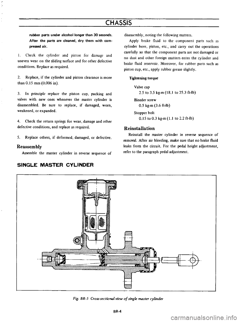
Fig
BR
5
Cross
sectional
view
of
single
master
cylinder
BR
4
Page 145 of 513
BRAKE
Brake
pedal
height
I
Fl
I
Jl
BRAKE
MASTER
CYllN
ADJU
SHI
1
I
195mm
001971011
THICKNESSIO
8
mm
00315
Inl
116mm
00630In
TOP
LAMP
SWrTCH
r
b
O
ZOlTlI
I
A
12
n
Y
1
O
09
ttr
i
l
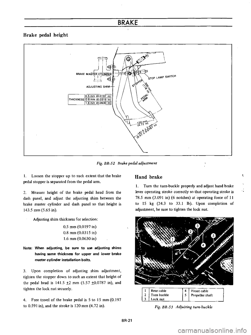
Fig
BR
52
Brake
pedal
adjustment
1
Loosen
the
stopper
up
to
such
extent
that
the
brake
pedal
stopper
is
separated
from
the
pedal
arm
2
Measure
height
of
the
brake
pedal
head
from
the
dash
panel
and
adjust
the
adjusting
shim
between
the
brake
master
cylinder
and
dash
panel
so
that
height
is
143
5
mm
5
65
in
Adjusting
shim
thickness
for
selection
0
5
mm
0
0197
in
0
8
mm
0
0315
in
1
6
mm
0
0630
in
Note
When
adjusting
be
sure
to
use
adjusting
shims
having
same
thickness
for
upper
and
lower
brake
master
cylinder
installation
bolts
3
Upon
completion
of
adjusting
shim
adjustment
tighten
the
stopper
down
to
such
an
extent
that
height
of
the
pedal
head
is
141
5
t2
mm
5
57
to
0787
in
and
tighten
the
lock
nut
securely
4
Free
travel
of
the
brake
pedal
is
5
to
15
mm
0
197
to
0
591
in
and
the
stroke
is
120
mm
4
72
in
Hand
brake
Turn
the
turn
buckle
properly
and
adjust
hand
brake
lever
operating
stroke
correctly
so
that
operating
stroke
is
78
5
mm
3
091
in
6
notches
at
operating
force
of
11
to
15
kg
24
3
to
33
1
1b
Upon
completion
of
adjustment
be
sure
to
tighten
the
lock
nut
I
I
Rear
cable
2
Turn
buckle
3
Lock
nut
1451
Front
cable
Propeller
shaft
Fig
BR
53
Adjusting
turn
buckle
BR
21
Page 146 of 513
CHASSIS
2
Upon
completion
of
the
adjustment
release
the
hand
brake
lever
and
make
sure
that
the
rear
wheels
are
not
braked
Normal
stroke
78
5
mm
3
091
in
6
notches
Limited
stroke
136
0
mm
5
35
in
10
notches
The
term
Stroke
means
height
from
the
standard
position
220
mm
8
7
in
above
the
hand
brake
lever
fulcrum
Note
Readjust
hand
brake
stroke
when
it
reaches
the
limited
stroke
136
mm
5
35
inl
10
notches
Bleeding
hydraulic
system
Bleeding
the
hydraulic
brake
system
deserves
much
attention
as
it
is
an
essential
factor
for
regular
service
brake
operation
As
a
matter
of
fact
during
the
brake
service
air
is
likely
to
creep
into
the
circuit
with
the
result
that
the
fluid
action
is
altered
and
the
brake
pedal
becomes
spongy
at
the
travel
end
Bleeding
should
be
carried
out
at
first
with
the
masler
cylinder
then
from
the
longest
line
from
the
master
cylinder
and
then
finish
up
with
the
shortest
Note
Always
clear
away
any
dirt
around
master
cylinder
reservoir
cover
before
removing
cover
for
any
reason
Never
depress
pedal
while
brake
drums
are
removed
unless
bleeder
valve
is
open
Top
up
the
reservoir
master
cylinder
with
fluid
of
the
recommended
type
2
Thoroughly
wipe
the
bleeder
screw
and
from
any
mud
or
dust
present
so
that
the
outlet
hole
is
free
from
foreign
matter
3
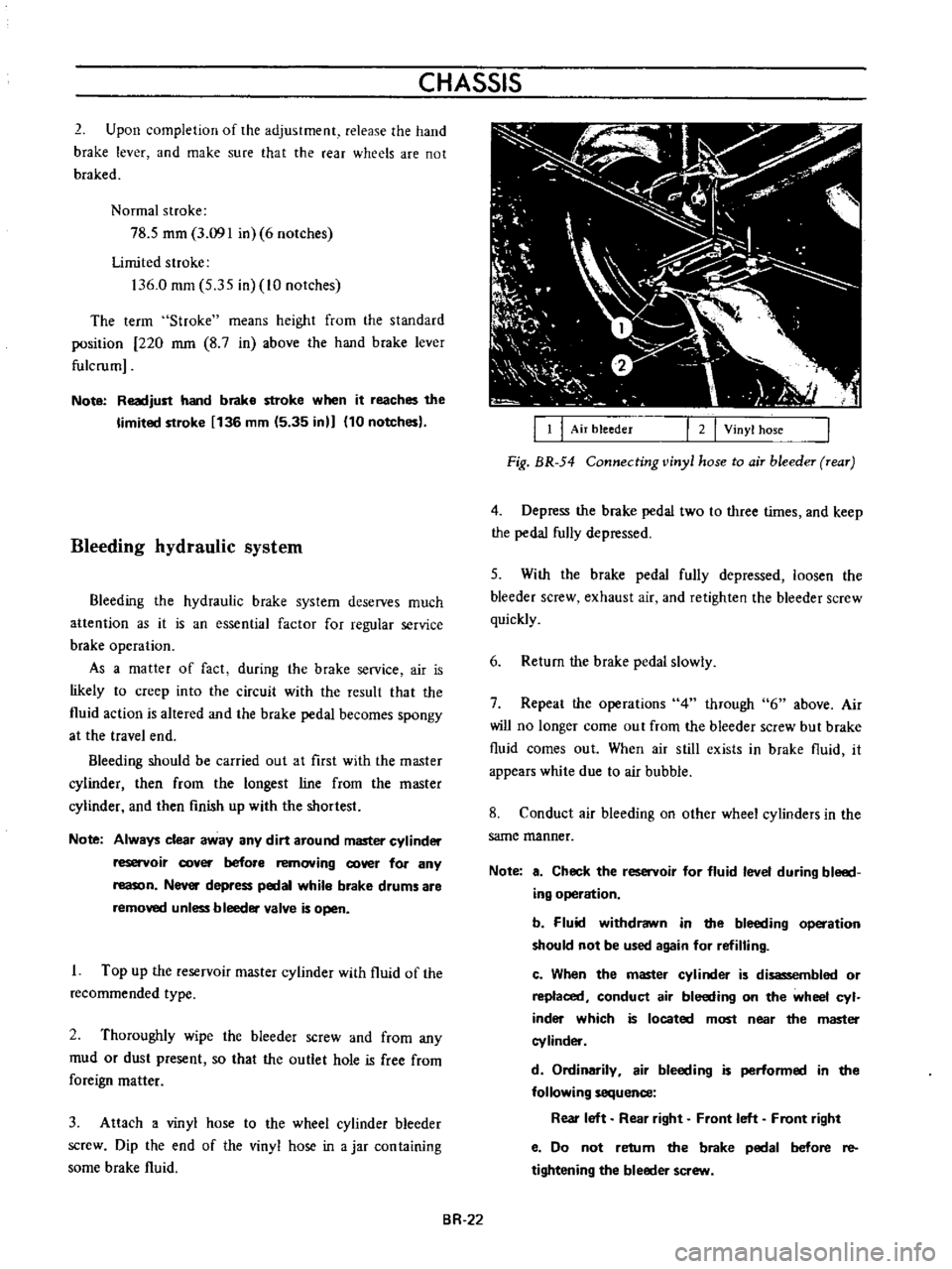
Attach
a
vinyl
hose
to
the
wheel
cylinder
bleeder
screw
Dip
the
end
of
the
vinyl
hose
in
a
jar
con
taining
some
brake
fluid
BR
22
I
I
I
Air
bleeder
I
2
I
Vinyl
hose
Fig
BR
54
Connecting
vinyl
hose
to
air
bleeder
rear
4
Depress
the
brake
pedal
two
to
three
times
and
keep
the
pedal
fully
depressed
5
With
the
brake
pedal
fully
depressed
loosen
the
bleeder
screw
exhaust
air
and
retighten
the
bleeder
screw
quickly
6
Return
the
brake
pedal
slowly
7
Repeat
the
operations
4
through
6
above
Air
will
no
longer
come
out
from
the
bleeder
screw
but
brake
fluid
comes
out
When
air
still
exists
in
brake
fluid
it
appears
white
due
to
air
bubble
8
Conduct
air
bleeding
on
other
wheel
cylinders
in
the
same
manner
Note
a
Check
the
reservoir
for
fluid
level
during
bleed
ing
operation
b
Fluid
withdrawn
in
the
bleeding
operation
should
not
be
used
again
for
refilling
c
When
the
master
cylinder
is
disassembled
or
replaced
conduct
air
bleeding
on
the
wheel
cyl
inder
which
is
located
most
near
the
master
cylinder
d
Ordinarily
air
bleeding
is
performed
in
the
following
sequence
Rear
left
Rear
right
Front
left
Front
right
e
Do
not
retum
the
brake
pedal
before
re
tightening
the
bleeder
screw
Page 147 of 513
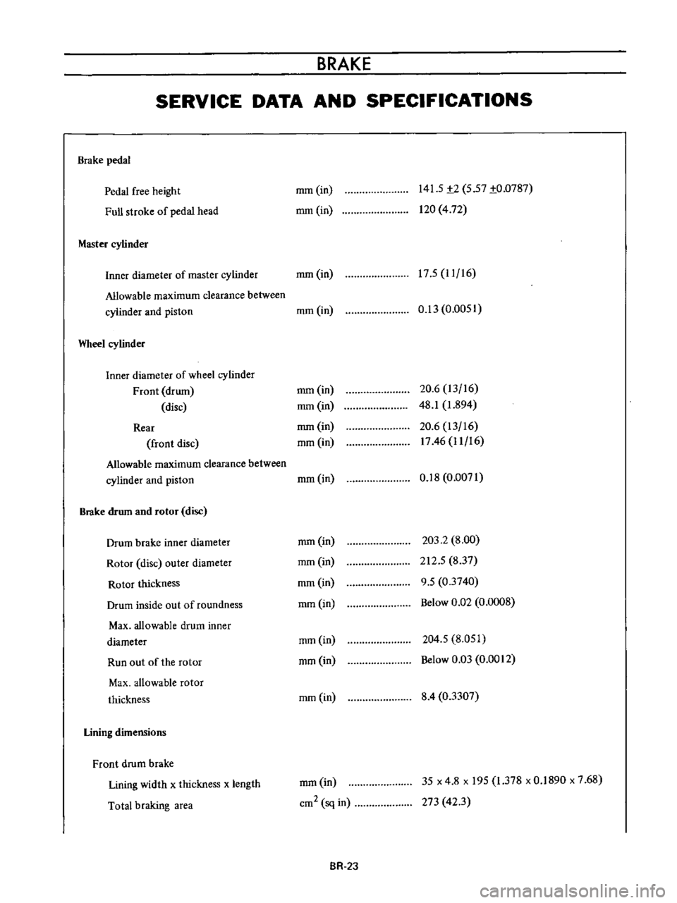
BRAKE
SERVICE
DATA
AND
SPECIFICATIONS
Brake
pedal
Pedal
free
height
Full
stroke
of
pedal
head
Master
cylinder
mm
in
mm
in
141
5
t2
5
57
to
0787
120
4
72
17
5
11
16
Inner
diameter
of
master
cylinder
mm
in
Allowable
maximum
clearance
between
cylinder
and
piston
mm
in
Wheel
cylinder
Inner
diameter
of
wheel
cylinder
Front
drum
disc
Rear
front
disc
Allowable
maximum
clearance
between
cylinder
and
piston
Brake
drum
and
rotor
disc
Drum
brake
inner
diameter
Rotor
disc
outer
diameter
Rotor
thickness
Drum
inside
out
of
roundness
Max
allowable
drum
inner
diameter
Run
out
of
the
rotor
Max
allowable
rotor
thickness
Lining
dimensions
Front
drum
brake
Lining
width
x
thickness
x
length
Total
braking
area
0
13
0
0051
mm
in
mm
in
mm
in
mm
in
20
6
13
16
48
1
1
894
20
6
13
16
1746
11
16
mm
in
0
18
0
0071
mm
in
mm
in
mm
in
mm
in
203
2
8
00
212
5
837
9
5
03740
Below
0
Q2
0
0008
mm
in
mm
in
204
5
8
051
Below
0
03
0
0012
mm
in
8
4
03307
mm
in
cm2
sq
in
35
x
4
8
x
195
1
378
x
0
1890
x
7
68
273
423
BR
2J
Page 149 of 513

Pedal
yields
under
slight
pressure
Excessive
pedal
travel
All
brakes
drag
One
brake
drags
Unbalanced
brakes
BRAKE
Use
of
a
brake
fluid
with
a
boiling
point
which
is
too
low
Reservoir
filler
cap
ven
t
hole
clogged
This
promotes
a
vacuum
in
master
cylinder
that
sucks
in
air
through
rear
seal
Deteriorated
check
valve
External
leaks
Master
cylinder
leaks
through
primary
cap
System
has
not
been
bled
Improperly
adjusted
clearance
Fluid
level
in
master
cylinder
is
too
low
Thermal
expansion
of
drums
due
to
over
heating
Insufficient
shoe
tlrdrum
clearance
Weak
shoe
return
springs
Brake
shoe
return
no
free
travel
Seized
master
cylinder
piston
Loose
or
damaged
wheel
bearings
Weak
broken
or
unhooked
brake
shoe
return
springs
Insufficient
clearance
between
brake
shoe
and
drum
Grease
or
oil
on
linings
Seized
piston
in
wheel
cylinder
Tires
improperly
inflated
Loose
wheel
bearing
BR
25
Change
with
the
specified
brake
fluid
and
bleed
system
Clean
reservoir
filler
cap
and
bleed
the
system
Fit
a
new
check
valve
and
bleed
the
system
Check
master
cylinder
piping
and
wheel
cylinder
for
leaks
and
make
necessary
re
pairs
Overhaul
master
cylinder
Bleed
the
system
Adjust
shoe
to
drum
clearance
Full
up
with
specified
brake
fluid
Bleed
the
system
if
required
Allow
drums
to
cool
off
Check
brake
shoe
linings
and
drums
Replace
damaged
parts
Adjust
clearance
Replace
the
springs
Adjust
pedal
height
Service
the
master
cylinder
replace
the
piston
and
bleed
the
system
Adjust
or
replace
wheel
bearings
Replace
spring
Adjust
brakes
Clean
brake
mechanism
replace
lining
and
correct
cause
of
grease
or
oil
getting
on
lining
Service
the
wheel
cylinder
and
bleed
the
system
Inflate
tires
to
correct
pressure
Adjust
wheel
bearing
Page 181 of 513
CHASSIS
Description
The
accelerator
linkage
is
lightv
eighL
and
onstfuction
is
such
that
the
linkage
operates
smoothly
and
is
unaffected
bv
engine
vibration
Adjustment
Play
of
accelerator
wire
I
Install
the
pedal
arm
side
securely
with
a
spring
clamp
2
Set
the
dash
board
side
Quter
case
stationarily
with
a
cap
nut
Do
not
set
the
carburetor
side
adjusting
unit
stationarily
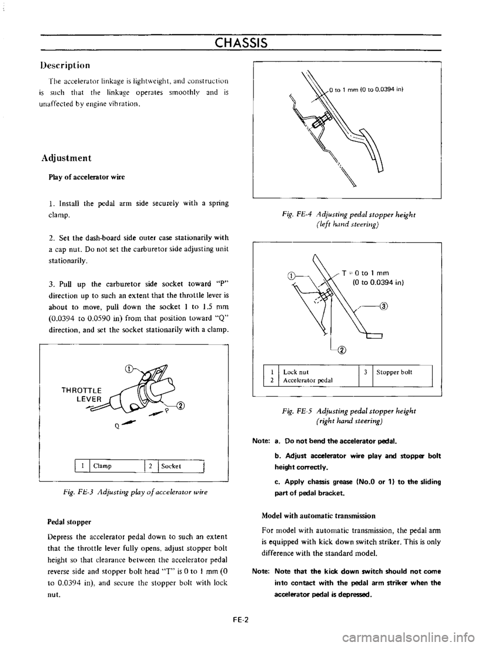
3
Pull
up
the
carburetor
side
socket
toward
P
direction
up
to
such
an
extent
that
the
throttle
lever
is
about
to
move
pull
down
the
socket
I
to
1
5
mm
0
0394
to
0
0590
in
frorn
that
position
toward
Q
direction
and
set
the
socket
stationarily
with
a
clamp
THROTTLE
LEVER
Q
I
I
I
Clamp
I
2
I
Sockel
Fig
FJ
3
Adjusting
play
of
a
ccelerator
wire
Pedal
stopper
Depress
the
accelerator
pedal
down
to
such
an
extent
that
the
throttle
lever
fully
opens
adjust
stopper
bolt
height
so
that
clearance
between
the
accelerator
pedal
reverse
side
and
stopper
bolt
head
T
is
0
to
I
mm
0
to
0
03Q4
in
and
secure
the
stopper
bolt
with
lock
nut
Fig
FE
4
1djusting
pedal
stopper
height
left
hand
steering
T
0
to
1
mm
0
to
0
0394
in
@
I
I
Lo
k
nut
2
Accelerator
pedal
I
3
I
Stopper
bolt
Fig
FE
5
Adjusting
pedal
stopper
height
right
hand
steering
Note
8
Do
not
bend
the
accelerator
pedal
b
Adjust
accelerator
wire
play
and
stopp
bolt
height
correctly
c
Apply
chassis
grease
No
a
or
1
to
the
sliding
part
of
pedal
bracket
Model
with
automatic
transmission
For
model
with
automatic
transmission
the
pedal
ann
is
equipped
with
kick
down
switch
striker
This
is
only
difference
with
the
standard
model
Note
Note
that
the
kick
down
switch
should
not
come
into
contact
with
the
pedal
arm
striker
when
the
accelerator
pedal
is
depressed
FE
2