1973 DATSUN B110 height
[x] Cancel search: heightPage 199 of 513
BODY
UNDERBODY
ALIGNMENT
CONTENTS
UNDERBODY
GENERAL
SERVICE
INFORMATION
ALIGNMENT
CHECKING
PROCEDURE
BF
9
BF
9
UNDERBODY
GENERAL
SERVICE
INFORMATION
Since
each
underbody
component
directly
affects
the
overall
strength
of
the
body
it
is
essential
that
proper
welding
sealing
and
rust
proofing
techniques
be
observed
during
service
operations
Whenever
the
body
is
repaired
be
sure
to
provide
the
repaired
body
parts
with
rust
proof
In
the
case
of
a
rust
proofmg
critical
underbody
component
it
is
essential
that
a
good
quality
type
air
dry
primer
such
as
corrosion
resistant
zinc
chromate
be
used
Do
not
use
combination
type
primer
surfacers
ALIGNMENT
CHECKING
PROCEDURE
Misalignment
in
the
underbody
affects
the
front
fender
door
trunk
lid
and
window
alignments
and
also
the
tail
gate
and
rear
body
opening
alignments
in
the
case
of
a
station
wagon
or
van
Underbody
misalignment
particularly
affects
the
suspension
system
thereby
causing
various
problems
that
arise
from
suspension
misalignment
It
is
essential
that
underbody
components
be
aligned
within
the
specified
dimensions
given
in
Figures
BF
13
14
and
IS
In
the
event
of
collision
damage
it
is
important
that
underbody
a1ignrnent
be
thoroughly
checked
and
if
necessary
realigned
to
the
specified
dirnensions
There
are
many
tools
that
may
be
ernployed
to
correct
collision
damage
such
as
frame
straightening
machines
external
pulling
equipment
other
standard
body
jacks
PRINCIPLES
OF
TRAMMING
CAR
PREPARATION
TRAMMING
SEQUENCE
BF
9
BF
10
BF
10
To
assist
in
checking
alignment
of
the
underbody
components
repairing
minor
underbody
damage
or
locating
replacement
parts
the
following
underbody
dimensions
and
alignment
checking
information
are
presented
PRINCIPLES
OF
TRAMMING
All
reference
locations
shown
in
Figure
BF
13
14
and
15
are
symmetrical
at
the
centerline
of
the
vehicle
For
example
wheo
performing
a
crosHheck
of
the
body
floor
panel
dimensions
Figures
BF
I3
14
and
IS
the
diagonal
measurement
should
be
the
same
in
boflii
directions
Cross
checking
operations
are
used
to
deter
mine
the
relationship
between
two
locations
on
the
underbody
To
measure
the
distance
between
any
two
reference
points
on
the
underbody
accurately
two
specifications
are
required
I
The
horizontal
dimension
between
the
two
points
to
be
measured
2
The
vertical
dimension
from
the
datum
line
to
the
points
to
be
measured
For
an
example
the
diagonal
measurement
calculated
on
a
horizontal
plane
between
reference
points
of
dimension
line
L
shown
in
Figure
BF
I3
is
631
3
mm
24
8
in
The
specifications
from
the
datum
line
have
a
vertical
height
difference
of
11
6
mm
0
456
in
between
the
forward
location
of
dimension
L
at
vertical
dimension
80
0
mm
3
150
in
and
the
rearward
location
of
dimension
L
at
vertical
dimension
91
6
mm
3
606
in
The
vertical
pointer
used
at
the
forward
location
should
be
positioned
so
as
to
extend
11
6
mm
0
456
in
further
from
the
tram
bar
than
the
BF
9
Page 276 of 513
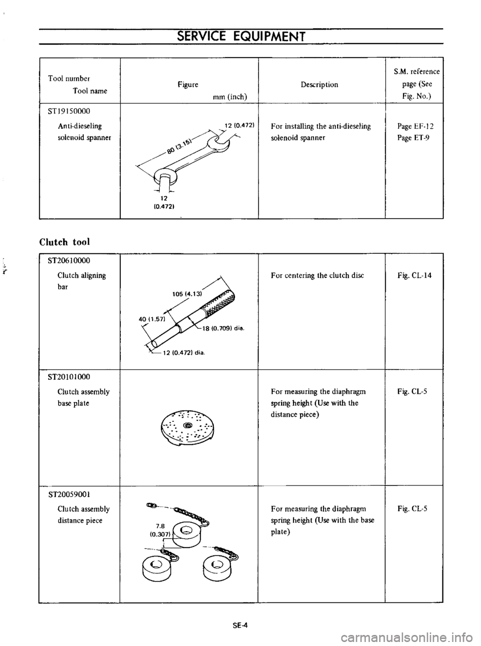
Tool
number
Tool
name
STl9
I
50000
Anti
dieseling
solenoid
spanner
Clutch
tool
ST20610000
Clutch
aligning
bar
ST20101000
Clutch
assembly
base
plate
ST20059001
Clu
tch
assembly
distance
piece
SERVICE
EQUI
PMENT
Figure
mm
inch
12
10
4721
0
o
8
C
307
l
j
@@
SE
4
Description
For
installing
the
anti
dieseling
solenoid
spanner
For
centering
the
clutch
disc
For
measuring
the
diaphragm
spring
height
Use
with
the
distance
piece
For
measuring
the
diaphragm
spring
height
Use
with
the
base
plate
S
M
reference
page
See
Fig
No
Page
EF
12
Page
ET
9
Fig
CL
14
Fig
CL
5
Fig
CL
5
Page 277 of 513
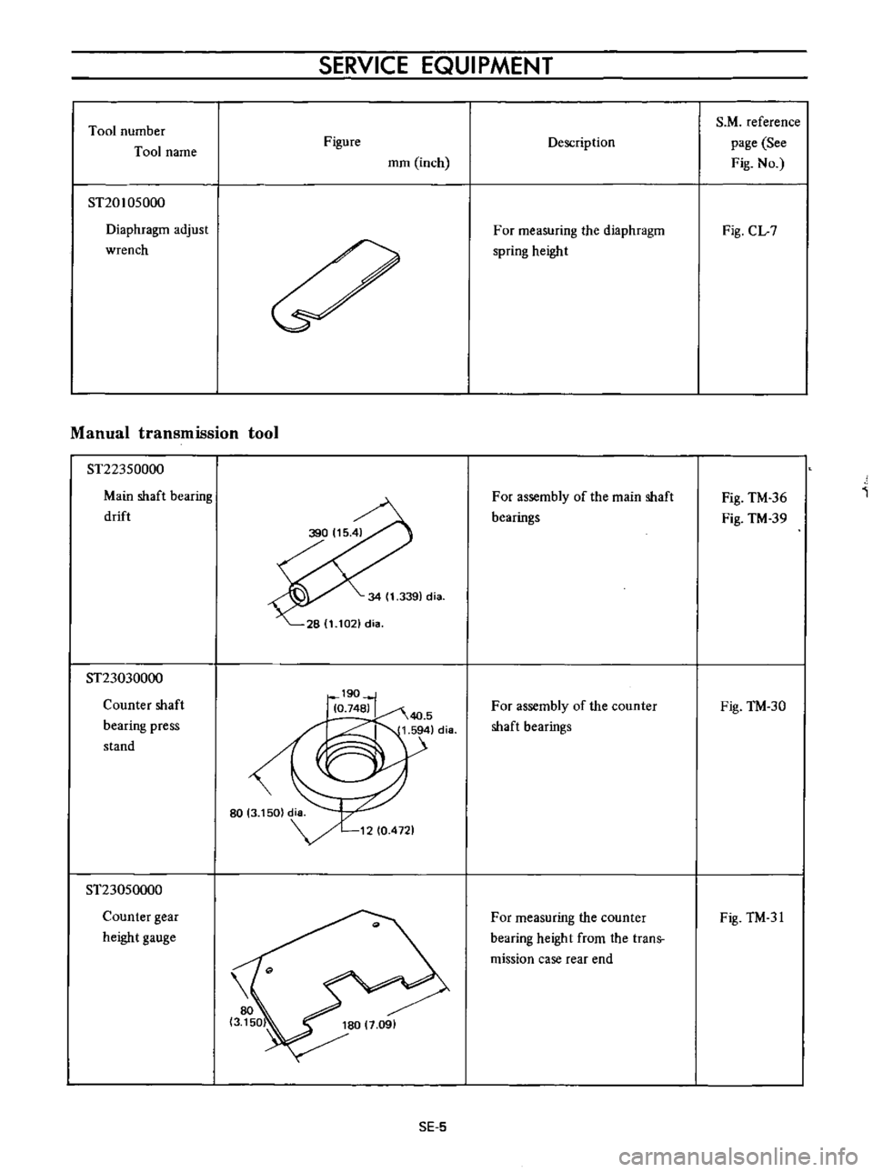
Tool
number
Tool
name
ST20105000
Diaphragm
adjust
wrench
SERVICE
EQUIPMENT
Figure
mm
inch
Manual
transmission
tool
ST22350000
Main
shaft
bearing
drift
ST23030000
Counter
shaft
bearing
press
stand
ST23050000
Counter
gear
height
gauge
SE
5
Description
For
measuring
the
diaphragm
spring
height
For
assembly
of
the
main
shaft
bearings
For
assembly
of
the
counter
shaft
bearings
For
measuring
the
counter
bearing
height
from
the
trans
mission
case
rear
end
S
M
reference
page
See
Fig
No
Fig
CL
7
Fig
TM
36
Fig
TM
39
Fig
TM
30
Fig
TM
31
Page 282 of 513
Tool
number
Tool
name
ST30600000
Drive
pinion
bearing
drift
ST31121000
Heigh
t
gauge
ST31122000
Dummy
shaft
ST3154llllUll
Drive
pinion
flange
wrench
ST3250S000
Side
bearing
adjust
weight
SERVICE
EQUIPMENT
Figure
mm
inch
15516
101
36114171dia
31
1
220
dia
70
2
756
cHa
r
84
513
271
20
O
Je7l
diil
L
9I17510Y
sE
lO
Description
For
installing
the
drive
pinion
rear
bearing
inner
race
For
height
adjustment
of
the
drive
pinion
For
height
adjustment
of
the
drive
pinion
For
removal
of
the
dri
ve
pinion
nut
For
determining
the
side
bearing
adjust
shim
S
M
reference
page
See
Fig
No
Page
PD
II
Fig
PD
22
Fig
PD
23
Fig
PD
22
Fig
PD
23
Fig
PD
12
Fig
PD
25
Page 329 of 513
ENGINE
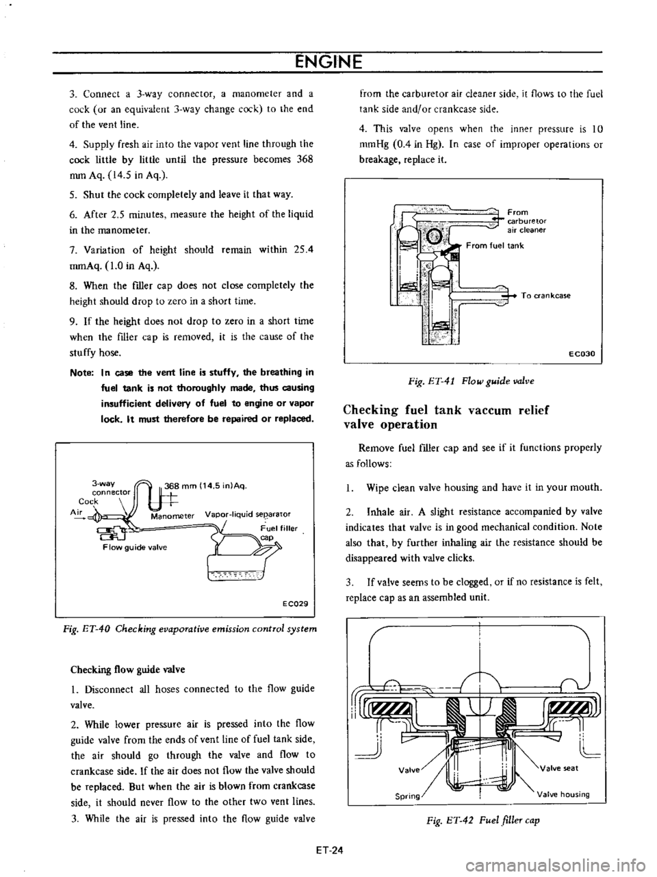
3
Connect
a
3
way
connector
a
manometer
and
a
cock
or
an
equivalent
3
way
change
cock
to
the
end
of
the
vent
line
4
Supply
fresh
air
into
the
vapor
vent
line
through
the
cock
little
by
little
until
the
pressure
becomes
368
mm
Aq
14
5
in
Aq
5
Shut
the
cock
completely
and
leave
it
that
way
6
After
2
5
minutes
measure
the
height
of
the
liquid
in
the
manometer
7
Variation
of
height
should
remain
within
254
mmAq
1
0
in
Aq
8
When
the
filler
cap
does
not
close
completely
the
height
should
drop
to
zero
in
a
short
time
9
If
the
height
does
not
drop
to
zero
in
a
short
time
when
the
filler
cap
is
removed
it
is
the
cause
of
the
stuffy
hose
Note
In
case
the
vent
line
is
stuffy
the
breathing
in
fuel
tank
is
not
thoroughly
made
thus
causing
insufficient
delivery
of
fuel
to
engine
or
vapor
lock
It
must
therefore
be
repaired
or
replaced
3
way
connector
Cock
Air
Manometer
Vapor
liquid
seearator
Flow
guide
valve
E
CQ29
Fig
ET
40
Checking
evaporative
emission
control
system
Checking
flow
guide
valve
I
Disconnect
all
hoses
connected
to
the
flow
guide
valve
2
While
lower
pressure
air
is
pressed
into
the
flow
guide
valve
from
the
ends
of
vent
line
of
fuel
tank
side
the
air
should
go
through
the
valve
and
flow
to
crankcase
side
If
the
air
does
not
flow
the
valve
should
be
replaced
But
when
the
air
is
blown
from
crankcase
side
it
should
never
flow
to
the
other
two
vent
lines
3
While
the
air
is
pressed
into
the
flow
guide
valve
from
the
carburetor
air
cleaner
side
it
flows
to
the
fuel
tank
side
and
or
crankcase
side
4
This
valve
opens
when
the
inner
pressure
is
10
mmHg
0
4
in
Hg
In
case
of
improper
operations
or
breakage
replace
it
From
carburetor
air
cleaner
From
fuel
tank
i
I
I
ti
i
i
1
1
i
To
ran
kcase
E
C030
Fig
ET
41
Flow
guide
valve
Checking
fuel
tank
vaCCUID
relief
valve
operation
Remove
fuel
filler
cap
and
see
if
it
functions
properly
as
follows
Wipe
clean
valve
housing
and
have
it
in
your
mouth
2
Inhale
air
A
slight
resistance
accompanied
by
valve
indicates
that
valve
is
in
good
mechanical
condition
Note
also
that
by
further
inhaling
air
the
resistance
should
be
disappeared
with
valve
clicks
3
If
valve
seems
to
be
clogged
or
if
no
resistance
is
felt
replace
cap
as
an
assembled
unit
T
1i
v
rUr1f
AlI
j
r
I
r
tLMJJl
rr
L
cc
11
J
v
II
4J
L
Valve
I
valve
seat
Spring
Valve
housing
Fig
ET
42
Fuel
filler
cap
ET
24
Page 355 of 513
ENGINE
MECHANICAL
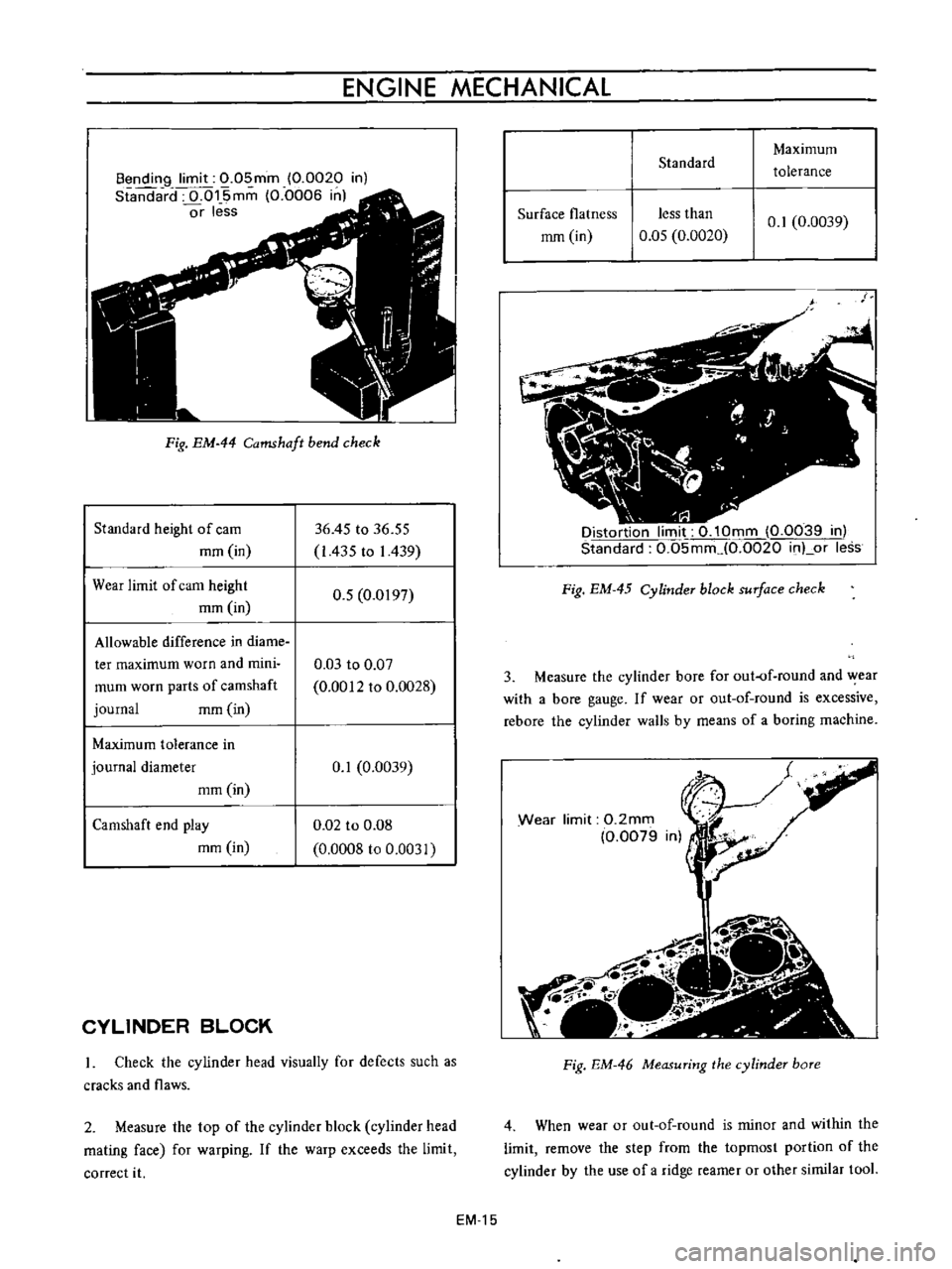
Bendin9
limit
0
05mm
0
0020
in
Standard
0
of5mm
0
0006
in
or
less
Fig
EM
44
Camshaft
bend
check
Standard
height
of
cam
mm
in
36
45
to
36
55
I
435
to
I
439
Wear
limit
of
cam
height
mm
in
0
5
0
0197
Allowable
difference
in
diame
ter
maximum
worn
and
mini
mum
worn
parts
of
camshaft
journal
mm
in
0
03
to
0
07
0
0012
to
0
0028
Maximum
tolerance
in
journal
diameter
mm
in
0
1
0
0039
Camshaft
end
play
mm
in
0
02
to
0
08
0
0008
to
0
0031
CYLINDER
BLOCK
Check
the
cylinder
head
visually
for
defects
such
as
cracks
and
flaws
2
Measure
the
top
of
the
cylinder
block
cylinder
head
mating
face
for
warping
If
the
warp
exceeds
the
limit
correct
it
EM
15
Standard
Maximum
tolerance
Surface
flatness
less
than
mm
in
0
05
0
0020
0
1
0
0039
Distortion
limit
0
10mm
0
0039
in
Standard
0
05mm
0
0020
inLor
less
Fig
EM
45
Cylinder
block
surface
check
3
Measure
the
cylinder
bore
for
out
of
round
and
wear
with
a
bore
gauge
If
wear
or
out
of
round
is
excessive
rebore
the
cylinder
walls
by
means
of
a
boring
machine
Wear
limit
0
2mm
0
0079
Fig
EM
46
Measuring
the
cylinder
bore
4
When
wear
or
out
of
round
is
minor
and
within
the
limit
remove
the
step
from
the
topmost
portion
of
the
cylinder
by
the
use
of
a
ridge
reamer
or
other
similar
tooL
Page 368 of 513
ENGINE
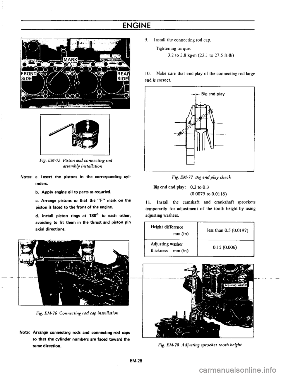
Fig
EM
75
Piston
and
connecting
rod
assembly
installation
Notes
8
I
nsert
the
pistons
in
the
corresponding
cyl
inders
b
Apply
engine
oil
to
parts
as
requried
c
Arrange
pistons
so
that
the
F
mark
on
the
piston
is
faced
to
the
front
of
the
engine
d
Install
piston
rings
at
180
to
each
other
avoiding
to
fit
them
in
the
thrust
and
piston
pin
axial
directions
Fig
EM
76
Connecting
rod
cap
installation
Note
Arrange
connecting
rods
and
connecting
rod
caps
so
that
the
cylinder
numbers
are
faced
toward
the
same
direction
EM
28
q
Install
the
connecting
rod
cap
Tightening
torque
32
to
3
8
kg
m
23
I
to
7
S
ft
lb
10
Make
sure
that
end
play
of
the
connecting
rod
large
end
is
correct
Big
end
play
j
I
Fig
EM
77
Big
end
play
check
Big
end
end
play
0
2
to
0
3
0
0079
to
0
0118
11
Install
the
camshaft
and
crankshaft
sprockets
temporarily
for
adjustment
of
the
tooth
height
by
using
adjusting
washers
Height
difference
mm
in
less
than
O
S
0
0197
Adjusting
washer
thickness
mm
in
O
IS
0
006
Fig
EM
78
Adjusting
sprocket
tooth
height
Page 374 of 513
ENGINE
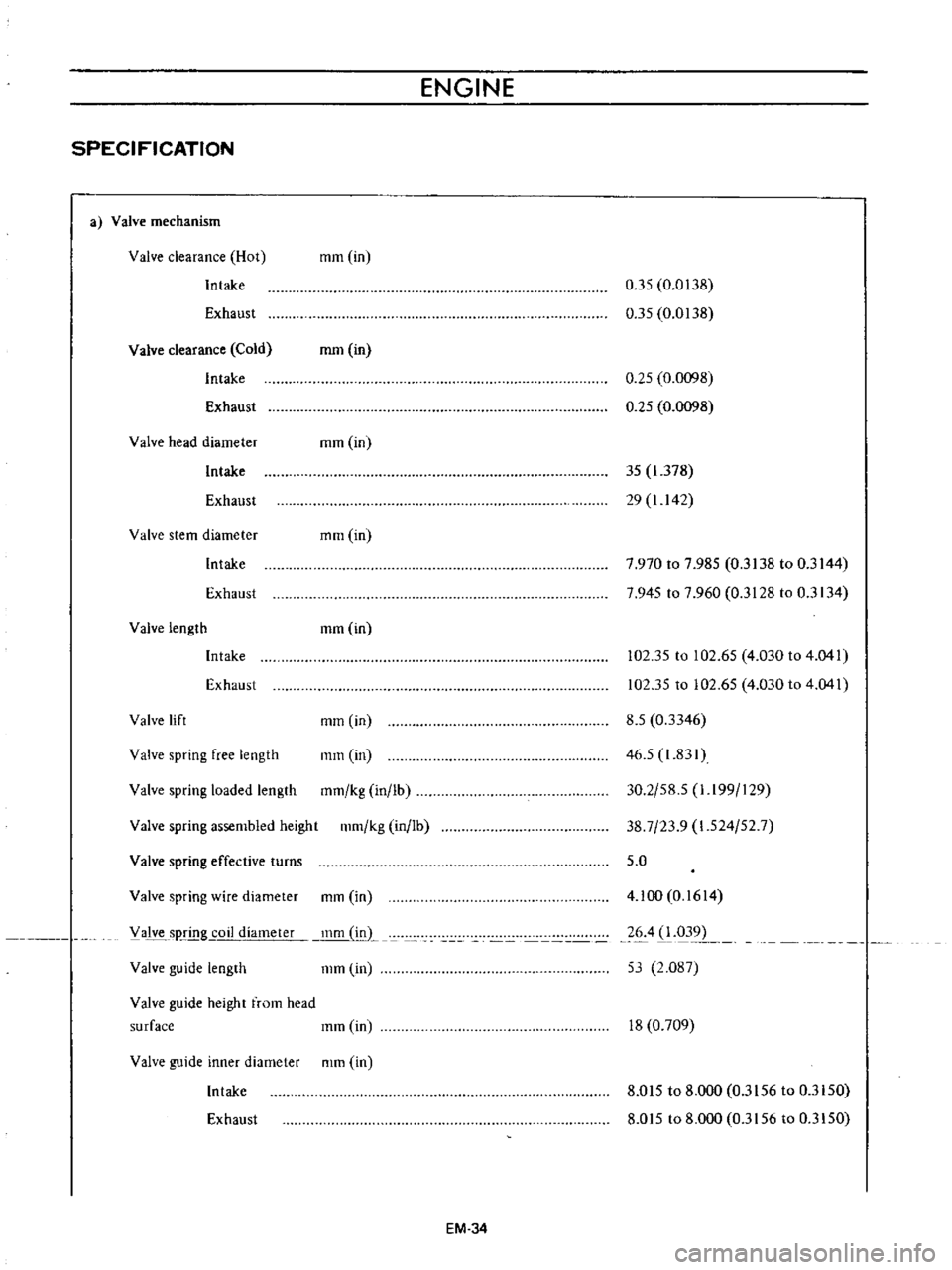
SPECIFICATION
a
Valve
mechanism
Valve
clearance
Hot
Intake
mm
in
Exhaust
0
35
0
0138
0
35
0
0138
Valve
clearance
Cold
Intake
Exhaust
mm
in
0
25
0
0098
0
25
0
0098
Valve
head
diameter
mm
in
Intake
35
1
378
29
1
142
Exhaust
Valve
stem
diameter
mm
in
Intake
7
970
to
7
985
0
3138
to
0
3144
7
945
to
7
960
0
3128
to
0
3134
Exhaust
Valve
length
mm
in
Intake
Exhaust
102
35
to
102
65
4
030
to
4
041
102
35
to
102
65
4
030
to
4
041
Valve
spring
assembled
height
111m
kg
in
lb
8
5
0
3346
46
5
1
831
30
2
58
5
1
I99
129
38
7
23
9
1
524
52
7
5
0
Valve
lift
mm
in
Valve
spring
free
length
mm
in
Valve
spring
loaded
length
mm
kg
in
lb
Valve
spring
effective
turns
Valve
guide
length
111m
in
4
100
0
1614
26
4
1
031
1
53
2
087
Valve
spring
wire
diameter
mm
in
V
alve
sp
g
coil
diameter
inm
L
Valve
guide
height
from
head
surface
111m
in
18
0
709
Valve
guide
inner
diameter
mm
in
Intake
8
015
to
8
000
0
3156
to
0
3150
Exhaust
8
015
to
8
000
0
3156
to
0
3150
EM
34