1973 DATSUN B110 alternator belt
[x] Cancel search: alternator beltPage 241 of 513
INSPECTION
Referring
to
the
wiring
diagram
check
the
wiring
harness
for
connection
with
electrical
equipment
and
connector
for
conned
ion
and
installation
When
checking
the
wiring
harness
note
the
following
matters
Connected
unit
should
not
be
loose
rusted
or
contaminated
2
Cable
insulator
cover
should
not
be
damaged
crack
ed
or
insulating
material
should
not
be
deteriorated
3
For
those
parts
which
are
grounded
through
the
installation
bolts
the
bolts
should
be
in
contact
with
the
body
completely
so
that
continuity
is
provided
in
between
the
body
and
bolts
4
Terminals
of
unit
through
which
current
flows
should
not
come
into
contact
with
other
metal
parts
5
No
erroneous
connection
should
be
present
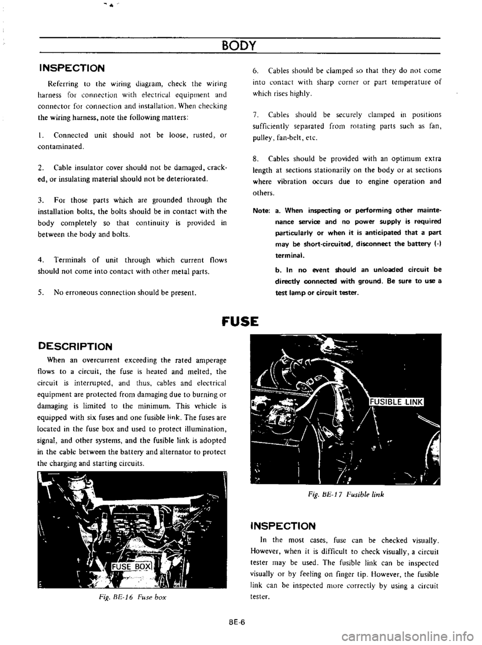
DESCRIPTION
When
an
overcunent
exceeding
the
rated
amperage
flows
to
a
circuit
the
fuse
is
heated
and
melted
the
circuit
is
interrupted
and
thus
cables
and
electrical
equipment
are
protected
from
damaging
due
to
burning
or
damaging
is
limited
to
the
minimum
This
vehicle
is
equipped
with
six
fuses
and
one
fusible
link
The
fuses
are
located
in
the
fuse
box
and
used
to
protect
illumination
signal
and
other
systems
and
the
fusible
link
is
adopted
in
the
cable
between
the
battery
and
alternator
to
protect
the
charging
and
starting
circuits
FiJ
BE
16
Fuse
box
BODY
6
Cables
should
be
damped
so
that
they
do
not
come
into
contact
with
sharp
corner
or
part
lernperature
of
which
rises
highly
7
Cables
should
be
securely
clamped
in
posItions
sufficiently
separated
from
rotating
parts
such
as
fan
pulley
fan
belt
etc
8
Cables
should
be
provided
with
an
optimum
extra
length
at
sections
stationarity
on
the
body
or
at
sections
where
vibration
occurs
due
to
engine
operation
and
others
Note
a
When
inspecting
or
performing
other
mainte
nance
service
and
no
power
supply
is
required
particularly
or
when
it
is
anticipated
that
a
part
may
be
short
circuited
disconnect
the
battery
H
terminal
b
In
no
event
should
an
unloaded
circuit
be
directly
connected
with
ground
Be
sure
to
use
a
test
lamp
or
circuit
tester
fUSE
Fig
BE
17
Fusible
link
INSPECTION
In
the
most
cases
fuse
can
be
checked
visually
However
when
it
is
difficult
to
check
visually
a
circuit
tester
may
be
used
The
fusible
link
can
be
inspected
visually
or
by
feeling
on
finger
tip
However
the
fusible
link
can
be
inspected
more
correctly
by
using
a
circuit
tester
BE
6
Page 372 of 513
ENGINE
27
Install
the
oil
pump
with
oil
filter
28
Install
the
alternator
fan
and
fan
belt
29
Install
the
fuel
pump
30
Install
the
distributor
assembly
Fig
EM
B7
Timing
maTk
Fig
EM
SS
Distributor
installation
EM
32
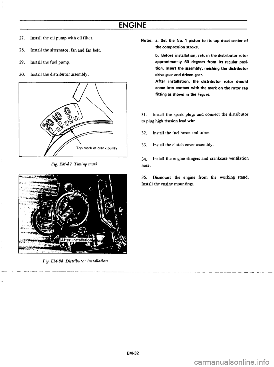
Notes
3
Set
the
No
1
piston
to
its
top
dead
center
of
the
compression
stroke
b
Before
installation
return
the
distributor
rotor
approximately
60
degrees
from
its
regular
posi
tion
Insert
the
assembly
meshing
the
distributor
drive
gear
and
driven
gear
After
installation
the
distributor
rotor
should
come
into
contact
with
the
mark
on
the
rotor
cap
fitting
as
shown
in
the
Figure
31
Install
the
spark
plugs
and
connect
the
distributor
to
plug
high
tension
lead
wire
32
Install
the
fuel
hoses
and
tubes
33
Install
the
clutch
cover
assembly
34
Install
the
engine
stingers
and
crankcase
ventilation
hose
35
Dismount
the
engine
from
the
working
stand
Install
the
engine
mountings
Page 437 of 513
ENGINE
ElECTRICAL
SYSTEM
CD
@
@
@
y
@
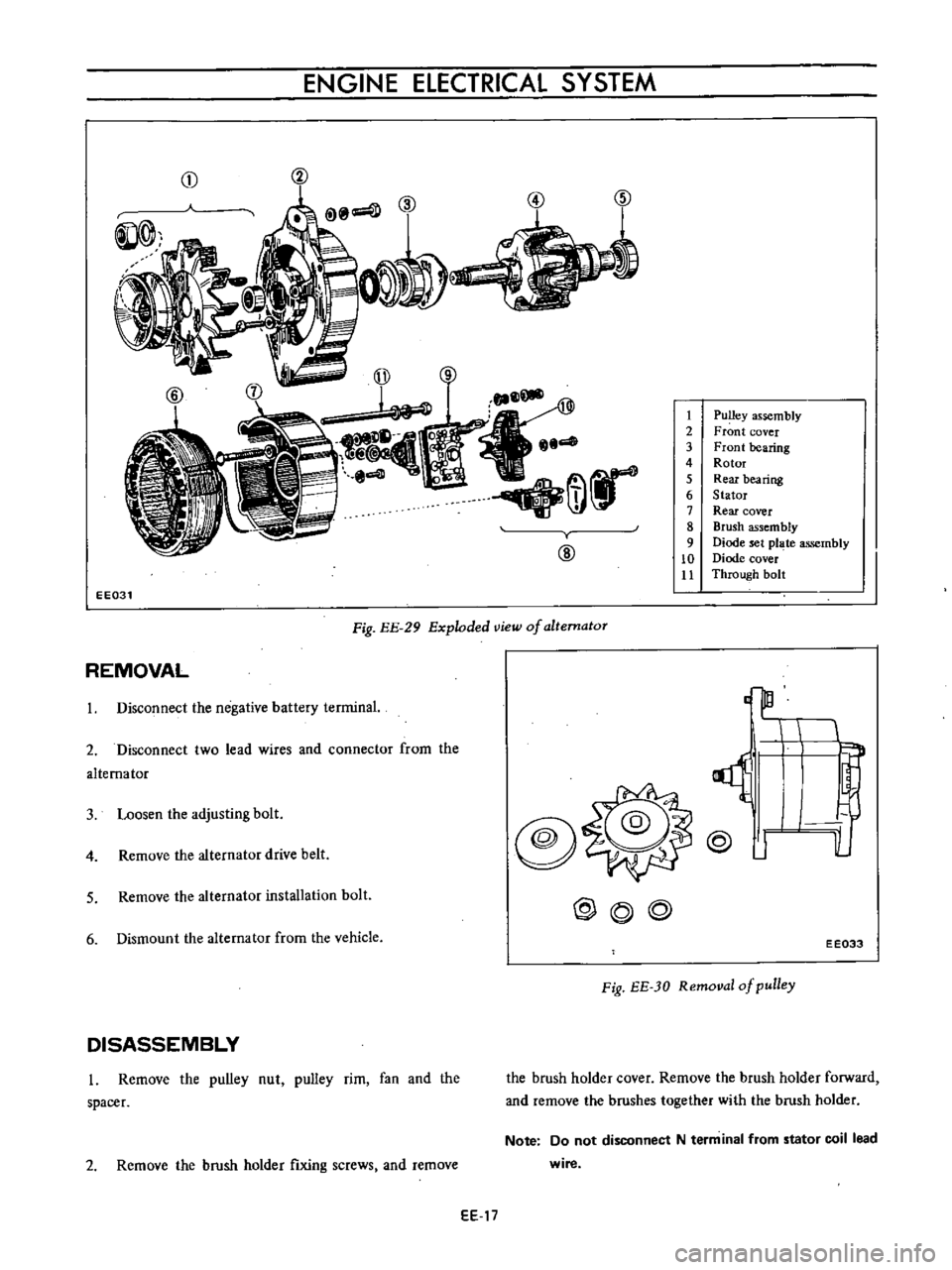
1
Pulley
assembly
2
Front
cover
3
Front
bearing
4
Rotor
5
Rear
bearing
6
Stator
7
Rear
cover
8
Brush
assembly
9
Diode
set
pl
te
assembly
10
Diode
cover
Jl
Through
bolt
EE031
Fig
EE
29
Exploded
view
of
altematoT
REMOVAL
3
Loosen
the
adjusting
bolt
@
o
lL
1
Disconnect
the
negative
battery
terminal
2
Disconnect
two
lead
wires
and
connector
from
the
alternator
4
Remove
the
alternator
drive
belt
@
J
5
Remove
the
alternator
installation
bolt
@@@
6
Dismount
the
alternator
from
the
vehicle
EE033
Fig
EE
JO
Removal
of
pulley
DISASSEMBLY
l
Remove
the
pulley
nut
pulley
rim
fan
and
the
spacer
the
brush
holder
cover
Remove
the
brush
holder
forward
and
remove
the
brushes
together
with
the
brush
holder
2
Remove
the
brush
holder
fixing
screws
and
remove
Note
Do
not
disconnect
N
term
inal
from
stator
coil
lead
wire
EE
17
Page 446 of 513
ENGINE
at
4
to
5
V
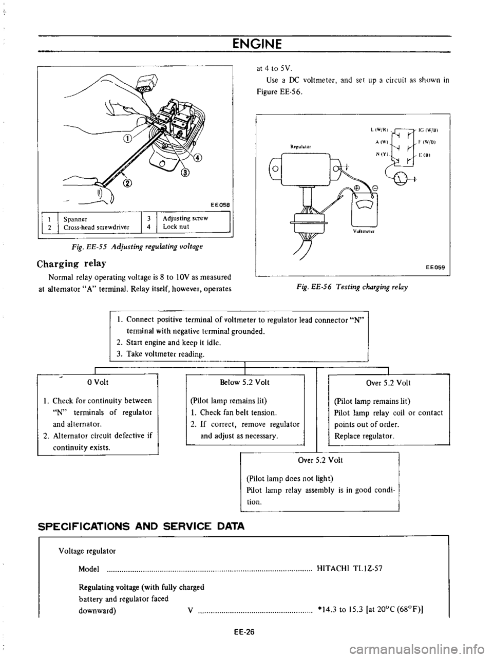
Use
i
f
DC
voltmeter
and
set
up
a
circuit
as
shown
in
Figure
EE
56
EEQ58
L
W
R
IG
Will
r
AI
W
lli
r
N
Y
vge
I
JJ
Rtl
ublOr
I
I
Spanner
Cross
head
screwdriver
I
I
Adjusting
screw
Lock
nut
Vollm
lcl
Fig
EE
55
Adjusting
Tegulating
voltage
Charging
relay
Normal
relay
operating
voltage
is
8
to
10V
as
measured
at
alternator
A
terminal
Relay
itself
however
operates
EE059
Fig
EE
56
Testing
chaTging
Telay
Connect
positive
terminal
of
voltmeter
to
regulator
lead
connector
N
terminal
with
negative
terminal
grounded
2
Start
engine
and
keep
it
idle
3
Take
voltmeter
reading
o
Volt
Below
5
2
Volt
I
Over
5
2
Volt
I
Check
for
continuity
between
N
terminals
of
regulator
and
alternator
2
Alternator
circuit
defective
if
continuity
exists
pilot
lamp
remains
lit
I
Check
fan
belt
tension
2
If
correct
remove
regulator
and
adjust
as
necessary
Pilot
lamp
remains
lit
Pilot
lamp
relay
coil
or
contact
points
out
of
order
Replace
regulator
Over
5
2
Volt
Pilot
lamp
does
not
light
Pilot
lamp
relay
assembly
is
in
good
condi
tion
SPECIFICATIONS
AND
SERVICE
DATA
Voltage
regulator
Model
HITACHI
TLl
Z
57
Regulating
voltage
with
fully
charged
battery
and
regulator
faced
downward
V
14
3
to
15
3
at
200C
680F
EE
26
Page 447 of 513
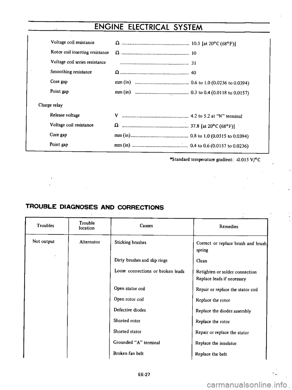
ENGINE
ELECTRICAL
SYSTEM
Rotor
coil
inserting
resistance
n
n
10
5
at
20DC
68DF
10
Voltage
coil
resistance
Core
gap
Point
gap
rnm
in
mm
in
31
40
0
6
to
1
0
0
0236
to
0
0394
0
3
to
0
4
0
0118
to
0
0157
Voltage
coil
series
resistance
Smoothing
resistance
n
Charge
relay
Release
voltage
Voltage
coil
resistance
V
4
2
to
5
2
at
N
terminal
n
37
8
at
20DC
68DF
mm
in
0
8
to
1
0
0
0315
to
0
0394
mm
in
0
4
to
0
6
0
0157
to
0
0236
Core
gap
Point
gap
Standard
temperature
gradient
D
015
VIDC
TROUBLE
DIAGNOSES
AND
CORRECTIONS
Troubles
Trouble
location
Causes
Remedies
Not
output
Alternator
Sticking
brushes
Correct
or
replace
brush
and
brush
spring
Dirty
brushes
and
slip
rings
Clean
Loose
connections
or
broken
leads
Retighten
or
solder
connection
Replace
leads
if
necessary
Open
stator
coil
Repair
or
replace
the
stator
coil
Open
rotor
coil
Replace
the
rotor
Defective
diodes
Replace
the
diodes
assembly
Shorted
rotor
Replace
the
rotor
Shorted
stator
Repair
or
replace
the
stator
Grounded
A
terminal
Replace
the
insulator
Broken
fan
belt
Replace
the
belt
EE
27
Page 448 of 513
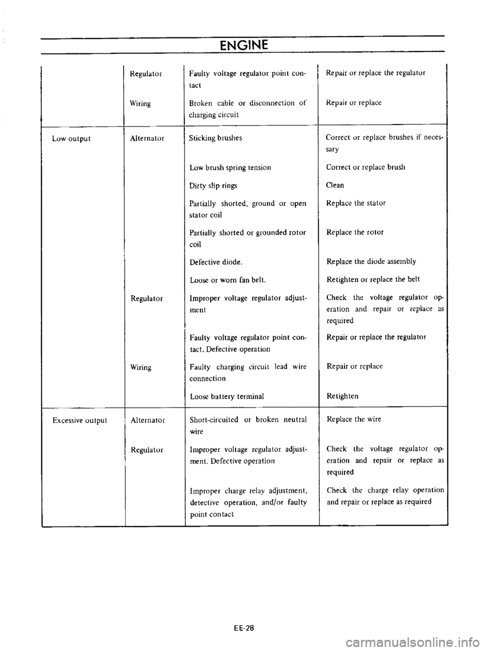
Low
output
Excessive
output
Regulator
Wiring
Alternator
Regula
tor
Wiring
Alternator
Regulatur
ENGINE
Faulty
voltage
regulator
point
con
tact
Broken
cable
or
disconnection
of
charging
cireui
t
Sticking
brushes
Low
brush
spring
tension
Dirty
slip
rings
Partially
shorted
ground
or
open
stator
coil
Partially
shorted
or
grounded
rotor
coil
Defective
diode
Loose
or
worn
fan
belt
Improper
voltage
regulator
adjust
ment
Faulty
voltage
regulator
point
con
tact
Defective
operation
Faulty
charging
circuit
lead
wire
connection
Loose
battery
terminal
Short
circuited
or
broken
neutral
wire
Improper
voltage
regulator
adjust
ment
Defective
operation
Improper
charge
relav
adjustment
detective
operation
and
or
faulty
point
contact
EE
28
Repair
or
replace
the
regulatur
Repair
or
replace
Correct
or
replace
brushes
if
neces
sary
Correct
or
replace
brush
Clean
Replace
the
stator
Replace
the
rotor
Replace
the
diode
assembly
Retighten
or
replace
the
belt
Check
the
voltage
regulator
op
eration
and
repair
or
replace
as
required
Repair
or
replace
the
regulator
Repair
or
replace
Retighten
Replace
the
wire
Check
the
voltage
regulator
op
eration
and
repair
or
replace
as
required
Check
the
charge
relay
operation
and
repair
or
replace
as
required