1973 DATSUN B110 manual transmission
[x] Cancel search: manual transmissionPage 6 of 513
CHASSIS
HYDRAULIC
CONTROL
SYSTEM
l
FUNCTIONS
OF
HYDRAULIC
CONTROL
UNIT
AND
VALVES
Oil
pump
Manual
linkage
Vacuum
diaphragm
Downshift
solenoid
Governor
valve
Control
valve
assembly
HYDRAULIC
SYSTEM
AND
MECHANICAL
OPERATION
CONTENTS
P
range
Park
R
range
Reverse
N
range
Neutral
D
range
Low
gear
D2
range
2nd
gear
D3
range
Top
gear
D
range
kick
down
2
range
2nd
gear
1
range
Low
gear
12
range
2nd
gear
AT
4
AT
4
AT
5
AT
5
AT
5
AT
5
AT
7
AT13
AT
14
AT
16
AT
18
AT
20
AT
22
AT
24
AT
26
AT
28
AT
30
AT
32
FUNCTIONS
OF
HYDRAULIC
CONTROL
UNIT
AND
VALVES
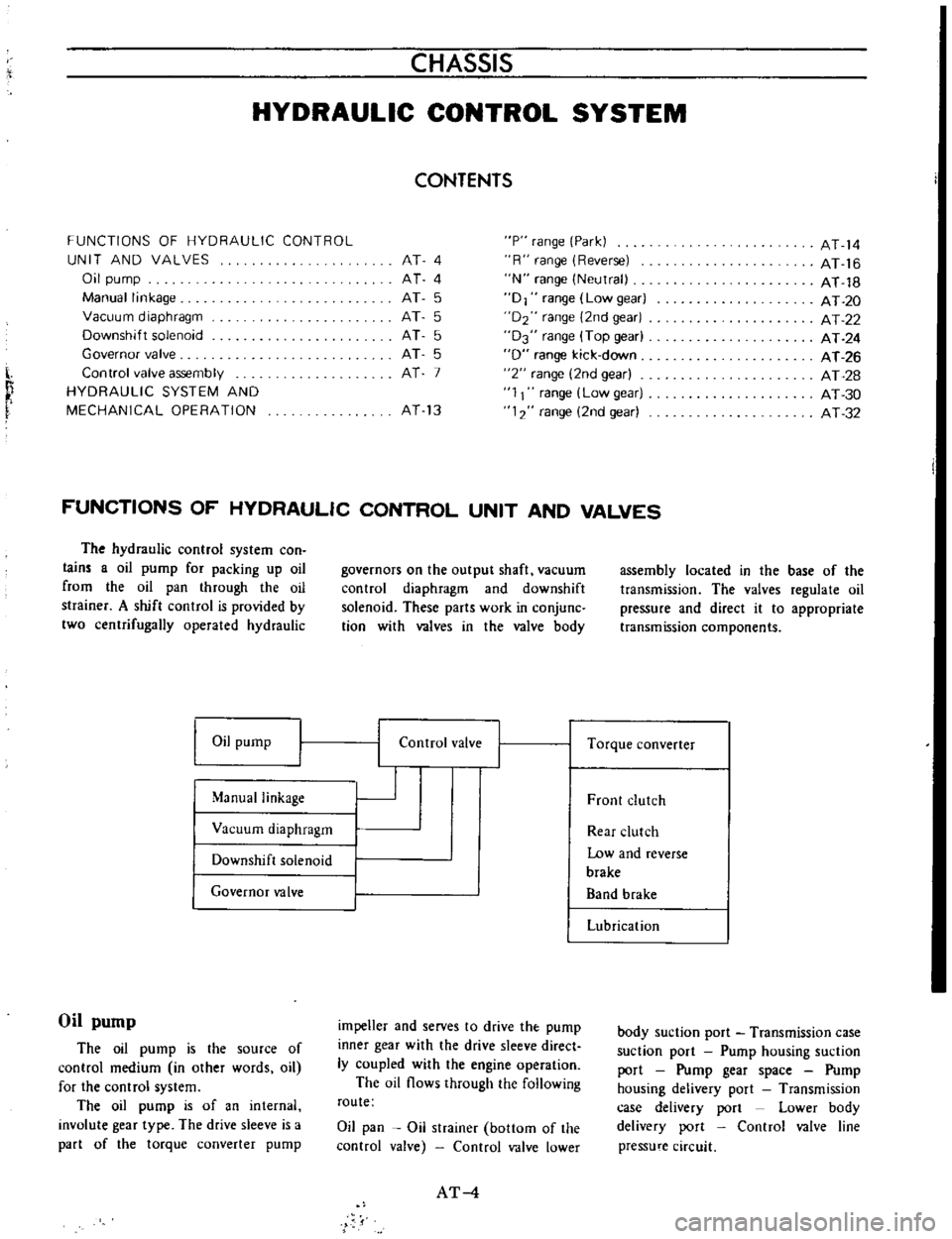
The
hydraulic
control
system
con
lain
a
oil
pump
for
packing
up
oil
from
the
oil
pan
through
the
oil
strainer
A
shift
control
is
provided
by
two
centrifugally
operated
hydraulic
Oil
pump
Manual
linkage
Vacuum
diaphragm
Downshift
solenoid
Governor
valve
Oil
pump
The
oil
pump
is
the
source
of
control
medium
in
other
words
oil
for
the
control
system
The
oil
pump
is
of
an
internal
involute
gear
type
The
drive
sleeve
is
a
part
of
the
torque
converter
pump
governors
on
the
output
shaft
vacuum
control
diaphragm
and
downshift
solenoid
These
parts
work
in
conjunc
tion
with
valves
in
the
valve
body
I
I
Control
valve
impeller
and
serves
to
drive
the
pump
inner
gear
with
the
drive
sleeve
direct
ly
coupled
with
the
engine
operation
The
oil
flows
through
the
following
route
Oil
pan
Oil
strainer
bottom
of
the
control
valve
Control
valve
lower
AT
4
assembly
located
in
the
base
of
the
transmission
The
valves
regulate
oil
pressure
and
direct
it
to
appropriate
transmission
components
I
Torque
converter
Front
clutch
Rear
clutch
Low
and
reverse
brake
Band
brake
Lubrication
body
suction
port
Transmission
case
suction
port
Pump
housing
suction
port
Pump
gear
space
Pump
housing
delivery
port
Transmission
case
delivery
port
Lower
body
delivery
port
Control
valve
line
pressure
circuit
Page 7 of 513
AUTOMATIC
TRANSMISSION
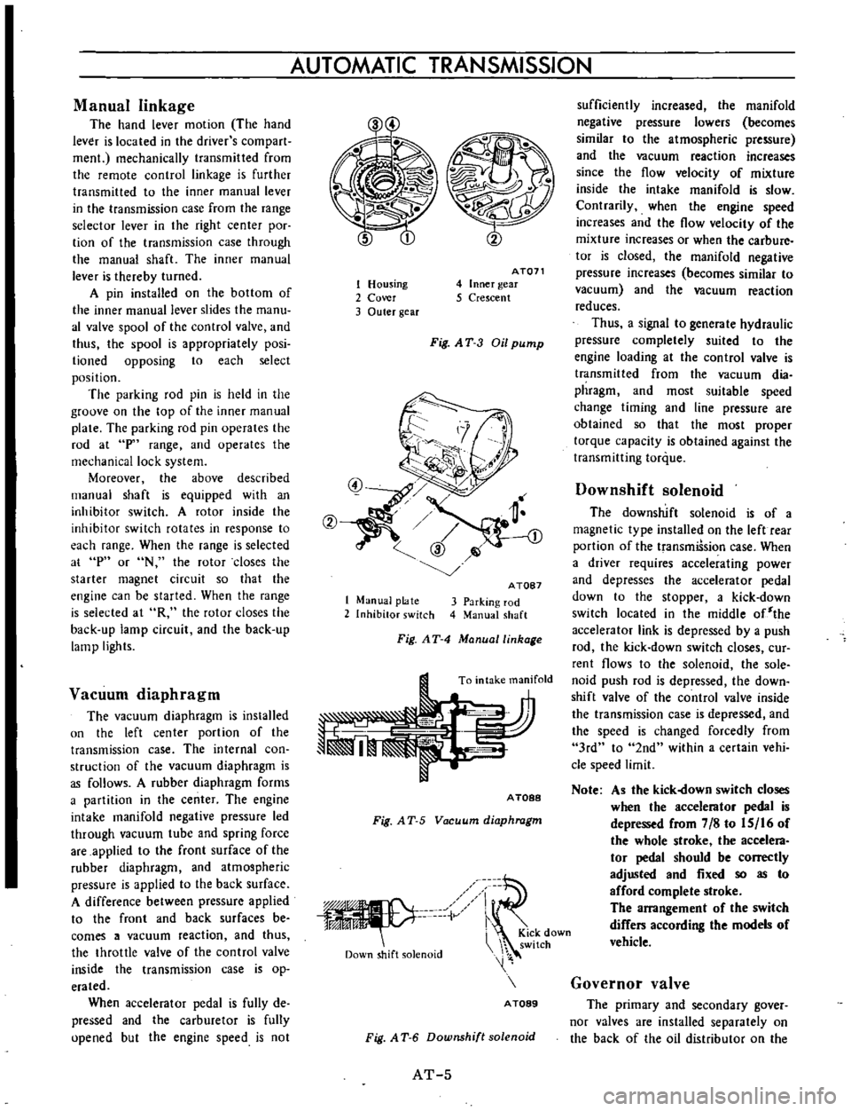
Manual
linkage
The
hand
lever
motion
The
hand
lever
is
located
in
the
driver
s
com
part
men
mechanically
transmitted
from
the
remote
control
linkage
is
further
transmitted
to
the
inner
manual
lever
in
the
transmission
case
from
the
range
selector
lever
in
the
right
center
poc
tion
of
the
transmission
case
through
the
manual
shaft
The
inner
manual
lever
is
thereby
turned
A
pin
installed
on
the
bottom
of
the
inner
manual
lever
slides
the
manu
al
valve
spool
of
the
control
valve
and
thus
the
spool
is
appropriately
posi
lioned
opposing
to
each
select
position
The
parking
rod
pin
is
held
in
the
groove
on
the
top
of
the
inner
manual
plate
The
parking
rod
pin
operates
the
rod
at
p
range
and
operates
the
mechanical
lock
system
Moreover
the
above
described
manual
shaft
is
equipped
with
an
inhibitor
switch
A
rotor
inside
the
inhibitor
switch
rotates
in
response
to
each
range
When
the
range
is
selected
at
p
or
N
the
rotor
closes
the
starter
magnet
circuit
so
that
the
engine
can
be
started
When
the
range
is
selected
at
R
the
rotor
closes
the
back
up
lamp
circuit
and
the
back
up
lamp
lights
Vacuum
diaphragm
The
vacuum
diaphragm
is
installed
un
the
left
center
portion
of
the
transmission
case
The
internal
con
struction
of
the
vacuum
diaphragm
is
as
follows
A
rubber
diaphragm
forms
a
partition
in
the
center
The
engine
intake
manifold
negative
pressure
led
through
vacuum
tube
and
spring
force
are
applied
to
the
front
surface
of
the
rubber
diaphragm
and
atmospheric
pressure
is
applied
to
the
back
surface
A
difference
between
pressure
applied
to
the
front
and
back
surfaces
be
comes
a
vacuum
reaction
and
thus
the
throttle
valve
of
the
control
valve
inside
the
transmission
case
is
op
erated
When
accelerator
pedal
is
fully
de
pressed
and
the
carburetor
is
fully
upened
but
the
engine
speed
is
not
1
Housing
2
Cover
3
Outer
gear
AT071
4
Inner
gear
5
Crescent
Fig
AT
3
Oil
pump
1
Manual
plate
2
Inhibitor
switch
A
TOB7
3
Parking
rod
4
Manual
shaft
Fig
AT
4
Manuallinhage
To
intake
manifold
A
TOBB
Fig
A
T
5
Vacuum
diaphragm
iV
Down
shift
solenoid
i
KiCk
down
switch
A
TOB9
Fig
A
T
6
Downshift
solenoid
AT
5
sufficiently
increased
the
manifold
negative
pressure
lowers
becomes
similar
to
the
atmospheric
pressure
and
the
vacuum
reaction
increases
since
the
flow
velocity
of
mixture
inside
the
intake
manifold
is
slow
Contrarily
when
the
engine
speed
increases
and
the
flow
velocity
of
the
mixture
increases
or
when
the
carbure
tor
is
closed
the
manifold
negative
pressure
increases
becomes
similar
to
vacuum
and
the
vacuum
reaction
reduces
Thus
a
signal
to
generate
hydraulic
pressure
completely
suited
to
the
engine
loading
at
the
control
valve
is
transmitted
from
the
vacuum
dia
phragm
and
most
suitable
speed
change
timing
and
line
pressure
are
obtained
so
that
the
most
proper
torque
capacity
is
obtained
against
the
transmitting
torque
Downshift
solenoid
The
downshift
solenoid
is
of
a
magnetic
type
installed
on
the
left
rear
portion
of
the
transmiSsion
case
When
a
driver
requires
accelerating
power
and
depresses
the
accelerator
pedal
down
to
the
stopper
a
kick
down
switch
located
in
the
middle
of
the
accelerator
link
is
depressed
by
a
push
rod
the
kick
down
switch
closes
cur
rent
flows
to
the
solenoid
the
sole
noid
push
rod
is
depressed
the
down
shift
valve
of
the
control
valve
inside
the
transmission
case
is
depressed
and
the
speed
is
changed
forcedly
from
3rd
to
2nd
within
a
certain
vehi
cle
speed
limit
Note
As
the
kick
own
switch
closes
when
the
accelerator
pedal
is
depressed
from
7
8
to
IS
16
of
the
whole
stroke
the
accelera
tor
pedal
should
be
correctly
adjusted
and
fixed
so
as
to
afford
complete
stroke
The
arrangement
of
the
switch
differs
according
the
models
of
vehicle
Governor
valve
The
primary
and
secondary
gover
nor
valves
are
installed
separately
on
the
back
of
the
oil
distributor
on
the
Page 8 of 513
I
transmission
output
shaft
They
op
erate
in
the
same
speed
as
that
of
the
output
shaft
In
other
wotds
they
operate
at
a
speed
in
proportion
to
the
vehicle
speed
To
those
valves
the
line
pressure
is
applied
as
the
input
ftom
the
control
valve
through
the
transmission
case
rear
flange
and
oil
distributor
The
governor
pressure
in
proportion
to
the
output
shaft
speed
vehicle
speed
is
led
to
the
shift
valve
of
the
control
valve
through
inverse
rou
te
as
the
output
and
thus
the
speed
change
and
the
line
pressure
are
controlled
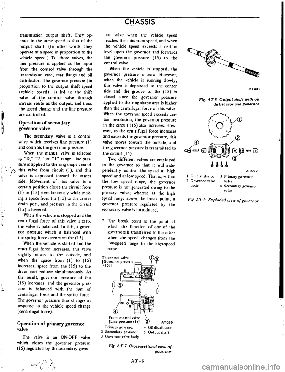
Operation
of
secondary
governor
valve
The
secondary
valve
is
a
control
valve
which
receives
line
pressure
I
and
controls
the
governor
pressure
When
the
manual
valve
is
selected
D
2
or
1
range
line
pres
sure
is
applied
to
the
ring
shape
area
of
f
this
valve
from
circuit
I
and
this
valve
is
depressed
toward
the
center
side
Movement
of
this
valve
to
a
certain
position
closes
the
circuit
from
I
to
15
simultaneously
while
mak
ing
a
space
from
the
15
to
the
center
drain
port
and
pressure
in
the
circuit
IS
is
lowered
When
the
vehicle
is
stopped
and
the
centrifugal
force
of
this
valve
is
zero
the
valve
is
balanced
In
this
a
gover
nor
pressure
which
is
balanced
with
the
spring
force
occurs
on
the
15
When
the
vehicle
is
started
and
the
centrifugal
force
increases
this
valve
slightly
moves
to
the
outside
and
when
the
space
from
I
to
15
increases
space
from
the
15
to
the
drain
port
reduces
simultaneously
As
the
result
governor
pressure
of
the
15
increases
and
the
governor
pres
sure
is
balanced
with
the
sum
of
centrifugal
force
and
the
spring
force
The
governor
pressure
thus
changt
s
in
response
to
the
vehicle
speed
change
centrifugal
force
Operation
of
primary
governor
valve
The
valve
is
an
ON
OFF
valve
which
closes
the
governor
pressure
15
regulated
by
the
secondary
gover
CHASSIS
nor
valve
when
the
vehicle
speed
reaches
the
minimum
speed
and
when
the
vehicle
speed
exceeds
a
certain
level
open
the
governor
and
forwards
the
governor
pressure
15
to
the
control
valve
When
the
vehicle
is
stopped
the
governor
pressure
is
zero
However
when
the
vehicle
is
running
slowly
this
valve
is
depressed
to
the
center
side
and
the
groove
to
the
IS
is
closed
since
the
governor
pressure
applied
to
the
ring
shape
area
is
higher
than
the
centrifugal
force
of
this
valve
When
the
governor
speed
exceeds
cer
tain
revolution
the
governor
pressure
in
the
circuit
15
also
increases
How
ever
as
the
centrifugal
force
increases
and
exceeds
the
governor
pressure
this
valve
moves
toward
the
outside
and
the
governor
pressure
is
transmitted
to
the
circuit
15
Two
different
valves
are
employed
in
the
governor
so
that
it
will
inde
pendently
control
the
speed
at
high
speed
and
at
low
speed
That
is
within
the
low
speed
range
the
governor
pressure
is
not
generated
owing
to
the
primary
valve
whereas
at
the
high
speed
range
above
the
break
point
a
governor
pressure
regula
ted
by
the
sec0Hdary
valve
is
introduced
The
break
point
is
the
point
at
which
the
function
of
one
of
the
govp
rnors
is
transferred
to
the
other
whee
the
speed
changes
from
the
w
speed
range
to
the
high
speed
range
To
con
trol
valve
Governor
pressure
tiS
y
ID
t
4
From
control
valve
Line
pressure
I
J
I
Primary
governor
2
Secondar
governor
3
Governor
valve
body
AT090
4
Oil
distributor
5
Output
shaft
Fig
AT
7
Cross
sectional
view
of
governor
AT
6
AT091
Fig
A
T
B
Output
shaft
with
oil
distributor
and
governor
I
Oil
distributor
2
Governor
valve
body
AT092
3
Primary
governor
valve
4
Secondary
governor
valve
Fig
A
T
9
Exploded
uiew
of
gouernor
Page 11 of 513

Control
valve
assembly
AUTOMATIC
TRANSMISSION
Oil
from
pump
ru
nn
i
I
I
I
Throttle
valve
I
I
1
m
nn
I
Auxiliary
valve
I
Regulator
valve
j
Manual
valve
I
Uoe
pressure
Speed
change
L
I
Governor
valve
I
I
valve
J
1
1
Clutch
and
brake
Flow
chart
of
control
valve
system
The
control
valve
assembly
receives
oil
from
the
pump
and
the
individual
signals
from
the
vacuum
diaphragm
and
transmits
the
individual
line
pres
sures
to
the
transmission
friction
ele
ment
torque
converter
circuit
and
lubricating
system
circuit
as
the
out
puts
To
be
more
specifically
the
oil
from
the
oil
pump
is
regulated
by
the
regulator
valve
and
line
pressures
build
up
The
line
pressures
are
fed
out
from
the
control
valve
assembly
as
they
are
through
various
direction
changeover
valves
including
ON
OFF
valve
and
regulator
valves
newly
reformed
to
a
throttle
system
oil
pressure
and
op
crates
other
valves
or
finally
the
line
pressure
are
transmitted
to
the
re
quired
clutch
or
brake
servo
piston
unit
in
response
to
the
individual
running
conditions
after
receiving
sig
nals
from
the
previously
described
vacuum
diaphragm
downshift
sole
noid
governor
valve
and
or
manual
linkage
The
control
valve
assembly
consists
of
the
following
valves
Pressure
regulator
valve
2
Manual
valve
3
1st
2nd
shift
valve
4
2nd
3rd
shift
valve
S
Pressure
modifier
valve
6
Yacuum
throttle
valve
7
Throttle
back
up
valve
8
Solenoid
downshift
valve
9
Second
lock
valve
0
2nd
3rd
timing
valve
Pressure
regulator
valve
PRV
The
pressure
regulator
valve
re
ceives
valve
spring
force
force
from
plug
created
by
the
throttle
pressure
16
and
line
pressure
7
and
force
of
the
throttle
pressure
18
With
the
mutual
operations
of
those
forces
the
PRY
regulates
the
line
pressure
7
to
the
most
suitable
pressures
at
the
individual
driving
conditions
The
oil
from
the
oil
pump
is
ap
plied
to
the
ring
shaped
area
through
orifice
20
As
the
result
the
PRY
is
depressed
downward
and
moves
from
port
7
up
to
such
extent
that
the
space
to
the
subsequent
drain
port
marked
with
x
in
Figure
AT
10
opens
slightly
Thus
the
line
pressure
7
is
balanced
with
the
spring
force
AT
7
and
the
PRY
is
thereby
balanced
In
this
the
space
from
the
port
7
to
the
subsequent
converter
oil
pressure
14
circuit
has
also
been
opened
As
the
result
the
converter
is
filled
with
the
pressurized
oil
in
the
circuit
14
and
the
oil
is
further
u
d
for
the
Iubrica
tion
of
the
rear
unit
Moreover
a
part
of
the
oil
is
branched
and
used
for
the
lubrication
of
front
unit
for
the
front
and
rear
clutches
When
the
accelerator
pedal
is
de
pressed
the
throttle
pressure
16
in
creases
as
described
in
the
preceding
paragraph
oil
pressure
is
applied
to
the
plug
through
orifice
21
and
the
pressure
is
added
to
the
spring
force
As
the
result
the
PRY
is
contrarily
depressed
upward
space
to
the
drain
port
is
reduced
and
the
line
pressure
7
increases
Afl
II
Jwi
06
A
J
L
I
7
I
tf
Iij
BL
i
il
J
jti
r
x
r
1
J
I
l
I
X
6
C
l
o
ii
J
f
A
T09S
Fig
AT
10
Pressure
regulator
value
tr
r
Page 20 of 513

R
range
Reverse
In
R
range
the
front
clutch
and
low
and
reverse
brake
are
applied
The
power
flow
is
through
the
input
shaft
front
clutch
connecting
sheU
and
to
the
sun
gear
Clockwise
rotatiun
of
the
sun
gear
causes
counterclockwise
rotation
of
the
rear
planetary
gears
With
the
connecting
drum
held
sta
tionary
by
the
low
and
reverse
brake
the
rear
planetary
gears
rotate
the
rear
internal
gear
and
drive
flange
counter
clockwise
The
rear
drive
flange
splined
to
the
output
shaft
rotates
the
output
shaft
counterclockwise
at
a
reduced
speed
with
an
increase
in
torque
for
reverse
gear
J
When
the
manual
valve
V
is
posi
tioned
at
R
range
the
oil
having
the
line
pressure
7
is
directed
to
the
line
pressure
circuits
5
and
6
The
pressure
in
the
circuit
ID
actuates
the
low
and
reverse
brake
after
being
introduced
into
the
line
pressure
cir
cuit
I2
through
the
lst
2nd
shift
valve
ID
The
pressure
in
the
circuit
operates
the
release
side
ofband
servo
and
the
front
clutch
after
being
led
to
the
line
pressure
circuit
10
through
the
2nd
3rd
shift
valve
@
The
throttle
pressure
16
and
the
line
pressure
6
which
vary
with
the
degree
of
the
depression
of
accelerator
pedal
both
act
on
the
pressure
regula
tor
valve
CD
and
press
its
valve
CD
increasing
the
line
pressure
7
In
R
range
the
governor
pressure
is
absent
making
all
sllch
valves
inoperative
as
the
lst
2nd
shift
valve
@
2nd
3rd
shift
valve
and
pressure
modifier
valve
@
CHASSIS
R
C
Fig
AT
26
Power
transmission
during
R
range
lI
a
Go
I
w
L
AT085
Fig
AT
27
Operation
of
each
mechani6m
duirng
OR
range
Clutch
low
Band
servo
One
Parking
Ran
Gear
ratio
reverse
way
pawl
Front
Rear
brake
Operation
Release
clutch
Park
on
on
Reverse
2
182
on
on
on
Neutral
01
low
2
458
nn
on
Drive
D2
Second
458
nn
on
OJ
Top
1
000
on
on
2
Second
458
nn
t2
Second
458
on
tt
low
2
458
on
on
AT
16
Page 24 of 513

CHASSIS
D
range
Low
gear
The
low
gear
in
D
range
is
somewhat
different
from
that
in
II
range
The
rear
clutch
is
applied
as
in
range
but
the
une
way
duldl
is
holding
the
connecling
drum
The
power
flow
is
the
same
as
in
11
range
That
is
the
power
flow
takes
place
through
Ihe
input
shaft
and
into
the
rear
clutch
The
input
shaft
is
splined
to
the
rear
clutch
drum
and
drives
it
Rotation
of
the
rear
clutch
dri
es
the
rear
clutch
hub
and
from
internal
gear
The
front
inlernal
gear
rotates
the
front
planetary
gears
clockwise
to
cause
the
sun
gear
to
rotate
counter
clockwise
Counterclockwise
rotation
of
the
sun
gear
turns
the
rear
planetary
gears
clockwise
With
the
Tear
plane
tary
carrier
held
stationary
by
the
one
way
clutch
the
clockwise
rotation
of
the
rear
planetary
gears
rotates
the
rear
internal
gear
and
drives
flange
clockwise
The
internal
drive
flange
is
splined
to
the
output
shaft
and
rotates
the
output
shaft
clockwise
When
the
manual
valve
is
posi
tioned
at
D
the
line
pressure
7
introduced
into
the
manual
valve
is
led
to
the
line
pressure
circuits
I
2
and
3
The
pressure
in
the
circuit
I
actuates
the
rear
clutch
and
the
gover
nor
and
at
the
same
time
operates
the
lst
2no
shift
valve
ID
to
change
the
speed
The
circuit
2
leads
to
the
second
lock
valve
@
The
circuit
3
actuales
the
2nd
3rd
shift
valve
0
for
the
2nd
3rd
speed
change
and
at
the
same
time
locks
the
second
lock
valve
@
The
throllIe
pressure
16
which
changes
with
the
degree
of
accelerator
pedal
depression
presses
the
pressure
regulator
valve
CD
and
increases
the
line
pressure
7
When
Ihe
speed
of
vehicle
has
increased
the
governor
pressure
J
5
inlroduced
from
the
line
pressure
circuit
ll
actuates
the
lst
2nd
shift
valve
ID
2nd
3rd
shift
valve
@
and
pressure
modifier
valve
@
When
the
governor
pressure
is
high
the
pressure
modifier
valve
CID
acts
in
such
a
direction
as
to
compress
C
AT080
Fig
A
T
30
Power
transmission
during
V
range
ATOP1
dmifi
Fig
AT
3
Operation
of
each
mechanism
during
VI
range
G
Clutch
Low
Band
rVo
One
Parking
Ro
reverse
woy
pawl
ratio
Front
Rear
brake
Operation
Release
clutch
Park
on
on
Reverse
2
182
on
on
on
Neutral
01
low
14
8
on
on
Drive
01
Second
1
458
on
on
03
Top
1
000
on
on
on
on
1
Second
1
458
on
on
tl
Second
1
458
on
on
1
II
low
2
458
on
on
rhe
spring
and
the
throttle
pressure
is
led
10
the
throllIe
pressure
18
This
pressure
acts
againsr
the
force
of
spring
of
the
pressure
regulator
valve
CD
and
also
against
the
Ihrollle
pres
sure
16
thus
lowering
the
line
pres
sure
7
The
governor
pressure
also
increases
with
the
speed
of
vehicle
exerting
a
pressure
on
one
side
of
the
1st
2nd
shift
valve
and
counteracts
the
throt
lie
p
ssure
19
line
pressure
I
and
the
spring
which
are
exerting
against
the
governor
pressure
Therefore
when
the
governor
pressure
exceeds
this
pressure
the
speed
is
shifted
from
Ihe
I
Sl
gear
10
the
2nd
gear
The
further
the
acceleraror
pedal
is
de
pressed
the
higher
becomes
the
throt
tle
pressure
19
increasing
the
gover
nor
pressure
and
shifting
the
speed
change
point
to
the
higher
side
AT
20
Page 27 of 513
AUTOMATIC
TRANSMISSION
D
range
2nd
gear
Q
FrO
ll
Cluteh
Low
to
R
B
e
8
eke
Torque
Con
ert
14
Throttle
Beck
up
V
l
iftV
I
a
Q
T
COU
P
R
V
A
Lubfkatlon
11
Drain
14
V
I
l
CID
V
Thro
Valli
7
If
SOle
Wo
Front
Lubrlc
at
n
Orific
Check
V
I
OralnValw
Tt
oW
Q
aln
V
l
S
P
Modit
V
2
S
13
j
P
RIGulato
Vel
@2nd
3
dShIH
V
I
13
c
33J
2nd
ShlftV
I
e
s
Manual
V
I
n
NOla
M
ked
X
r
Drein
r
D
I
U
jeeo
v
Primarv
Gov
no
Valva
Goyarno
Val
Li
p
su
aIGo
no
IMod
pr
surel
Gov
nO
pr
sur
TO
Qu
con
pr
Th
on
p
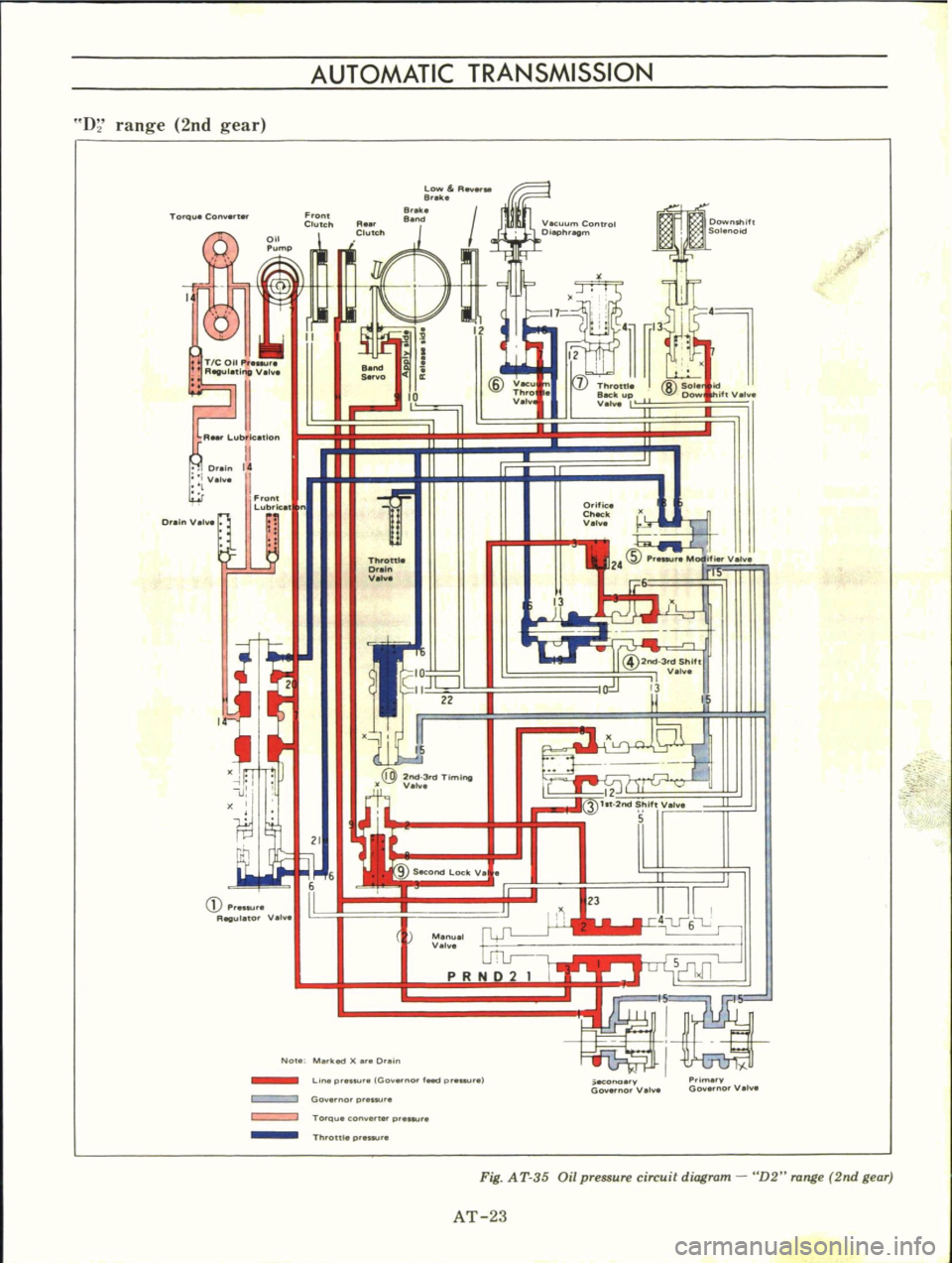
Fig
A
T
35
Oil
pressure
circuit
diagram
D2
range
2nd
gear
AT
23
Page 32 of 513
CHASSIS
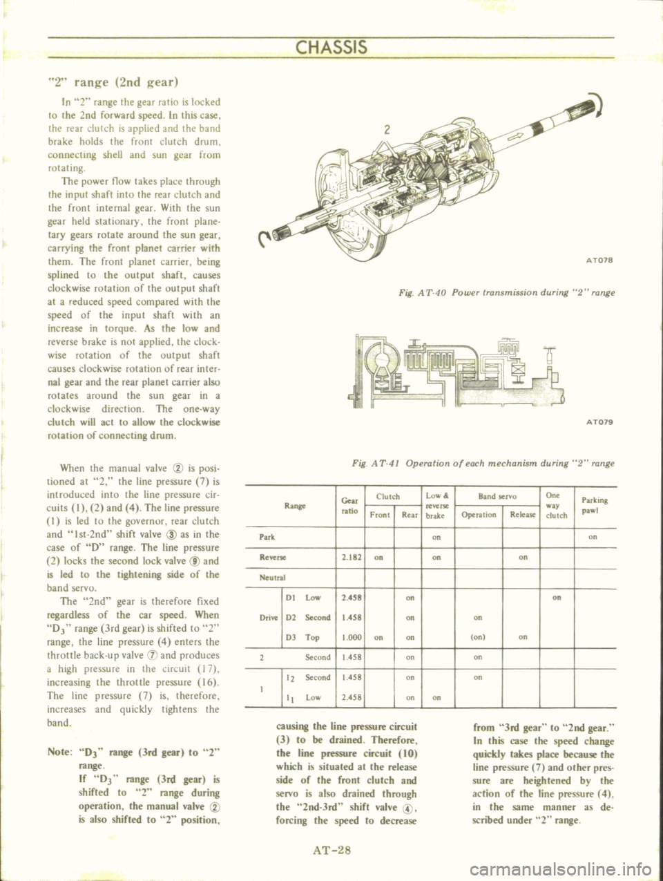
2
range
2nd
gear
In
2
range
the
gear
ratio
is
locked
to
the
2nd
forward
speed
In
this
case
the
rear
clutch
is
applied
and
the
band
brake
holds
the
front
clutch
drum
connecting
shell
and
sun
gear
from
rotating
The
power
flow
takes
place
through
the
input
shaft
into
the
rear
clutch
and
the
front
internal
gear
With
the
sun
gear
held
stationary
the
front
plane
lacy
gears
rotate
around
the
sun
gear
carrying
the
front
planet
carrier
with
them
The
front
planet
carrier
being
splined
to
the
output
shaft
causes
clockwise
rotation
of
the
output
shaft
at
a
reduced
speed
compared
with
the
speed
of
the
input
shaft
with
an
increase
in
torque
As
the
low
and
reverse
brake
is
not
applied
the
clock
wise
mlation
of
the
output
shaft
causes
clockwise
rotation
of
rear
inter
nal
gear
and
the
rear
planet
carrier
also
rotates
around
the
sun
gear
in
a
clockwise
direction
The
one
way
c1urch
will
act
to
allow
the
clockwise
rotation
of
connecting
drum
When
the
manual
valve
CV
is
posi
tioned
at
2
the
line
pressure
7
is
introduced
into
the
line
pressure
cir
cuits
I
2
and
4
The
line
pressure
I
is
led
to
the
governur
rear
dutch
and
Ist
2nd
shift
valve
ID
as
in
the
case
of
D
range
The
line
pressure
2
locks
the
second
lock
valve
@
and
is
led
to
the
tightening
side
of
the
band
servo
The
2nd
gear
is
therefore
fixed
regardless
of
the
car
speed
When
DJ
range
3rd
gear
is
shifted
to
2
range
the
line
pressure
4
enters
the
throttle
back
up
valve
IJ
and
produces
a
high
pressure
in
the
circuit
17
increasing
the
throttle
pressure
16
The
line
pressure
7
is
therefore
increases
and
quickly
tightens
the
band
Note
DJ
range
3rd
gear
to
2
range
If
DJ
range
3rd
gear
is
shifted
to
2
range
during
operation
the
manual
valve
CV
is
also
shifted
to
2
position
Fig
A
T
40
Powu
transmission
during
2
range
f
IY
9
3
AT079
Fig
A
T
41
Operation
of
each
mechanism
during
2
range
Gear
Clutch
low
Band
servo
On
Parking
Range
ratio
w
pawl
Front
Rear
brake
Operation
Relea
se
clutch
Park
on
on
Reverse
2
182
on
on
on
Neutral
I
t
Low
2
4S8
on
on
Drive
1
2
Second
1
458
on
on
1
Top
t
OOO
on
on
on
on
2
Second
1
458
on
on
12
Second
1
458
on
on
t
tt
Low
2
458
on
on
causing
the
line
pressure
circuit
3
to
be
drained
Therefore
the
line
pressure
circuit
10
which
is
situated
at
the
release
side
of
the
front
clutch
and
senro
is
also
drained
through
the
2nd
3rd
shift
valve
@
forcing
the
speed
to
decrease
from
3rd
gear
to
2nd
gear
In
this
case
the
speed
change
quickly
takes
place
because
the
line
pressure
7
and
other
pres
sure
are
heightened
by
the
action
of
the
line
pressure
4
in
the
same
manner
as
de
scribed
under
2
range
AT
28